EP0052832B1 - Tête de commande pour ressort pneumatique, notamment pour le réglage de sièges de meubles d'assise - Google Patents
Tête de commande pour ressort pneumatique, notamment pour le réglage de sièges de meubles d'assise Download PDFInfo
- Publication number
- EP0052832B1 EP0052832B1 EP81109614A EP81109614A EP0052832B1 EP 0052832 B1 EP0052832 B1 EP 0052832B1 EP 81109614 A EP81109614 A EP 81109614A EP 81109614 A EP81109614 A EP 81109614A EP 0052832 B1 EP0052832 B1 EP 0052832B1
- Authority
- EP
- European Patent Office
- Prior art keywords
- control
- housing
- shift
- pneumatic
- guide
- Prior art date
- Legal status (The legal status is an assumption and is not a legal conclusion. Google has not performed a legal analysis and makes no representation as to the accuracy of the status listed.)
- Expired
Links
Images

Classifications
-
- A—HUMAN NECESSITIES
- A47—FURNITURE; DOMESTIC ARTICLES OR APPLIANCES; COFFEE MILLS; SPICE MILLS; SUCTION CLEANERS IN GENERAL
- A47C—CHAIRS; SOFAS; BEDS
- A47C3/00—Chairs characterised by structural features; Chairs or stools with rotatable or vertically-adjustable seats
- A47C3/20—Chairs or stools with vertically-adjustable seats
- A47C3/30—Chairs or stools with vertically-adjustable seats with vertically-acting fluid cylinder
Definitions
- the invention relates to a control head for gas spring actuation, in particular for the seat plate adjustment on seating.
- Gas springs are used in seating, such as chairs, armchairs, vehicle seats and the like, both for the seat height adjustment and for the seat inclination adjustment. While the ejection force of the gas spring piston rod is usually only used for the upward movement of the unloaded seat plate and the piston rod is blocked after setting the desired seat height when adjusting the seat height, the damping-free mobility of the gas spring piston rod in connection with the natural ejection tendency and enable a weighing or rocking effect in cooperation with other suspension elements.
- the spring ratios can be selected so that the seat arrangement remains "braked" in the current state of equilibrium.
- the control element of the gas spring must be pressed in permanently, which can lead to complicated locking and unlocking mechanisms on seating furniture or to operating difficulties when adjusting the inclination.
- the resulting inadequacies also include that a seating position that is currently perceived as pleasant is changed again with a slight shift in body weight.
- the free mobility of the seat arrangement which is often too extensive as a result of the described control difficulties, also has the consequence that the seat arrangement can move back to an optically or usefully unfavorable starting position after being fully relieved, and / or immediately starts moving again when reloaded.
- the object of the invention is therefore to provide a means which allows the user of the seating furniture to select the type of seat inclination adjustment on gas spring-supported seating furniture in any hunt of the seating plate by a momentary push of a button.
- control head to be actuated by an impulse control command for determining the mode of operation of a gas spring is proposed, which control head is characterized by patent claim 1. Embodiments thereof are defined by the dependent claims.
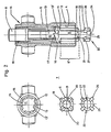
- 1A, 1B, 1 denotes the upper or piston rod-side end of a gas spring
- 2 the gas spring piston rod
- 3 the fastening end provided with a screw thread.
- This can be inserted directly, or, as shown, with the interposition of a threaded press-in bush 4 ', into the assembly opening 4 of the control head housing 5.
- the gas spring control rod is designated, which coaxially passes through the piston rod 2 and acts on one (not shown) gas spring valve arrangement.
- Fig. 1A the gas spring control rod 6 is in the ejected position (piston rod blocked), in Fig. 1 B, however, in the depressed position (piston rod "freely” movable).
- a locking mechanism, generally designated 7, in the interior of the control head housing 5 defines these two positions of the control rod 6, as will be described in detail later. From this latching mechanism 7, the end 8 of a control sleeve 9, which is designed, for example, in the form of a push button, also protrudes below the upper housing end.
- protruding coupling members are designated, which can be designed as a pivot pin, for example, when the gas spring is suspended. It goes without saying that the housing 5, which in the design of the gas spring control head according to the invention which is firmly connected to the piston rod 2, can also be provided with differently designed connection means.
- the housing 5 shown in more detail in FIG. 2 contains a continuous cylindrical recess 11 with a connection section 12 containing the already mentioned assembly opening 4, a (central) guide zone 13 and a centering and coupling section 14 on the actuating side.
- the one on the left in FIG. 2 the vertical sectional view shown plan view or front view shows the housing 5 seen from the piston rod side.
- the (middle) guide zone 13 preferably has a number of two to four guide cams 15 which are directed radially inward via a narrowed, offset base bore 13 'and which are arranged uniformly distributed over the circumference of the base bore 13' and are spaced apart from one another by an axially oriented guide groove 16 .
- the guide cams 15 are provided on their axial end facing the connection section 12 with locking teeth 17, the peripheral profile of which best emerges from FIGS. 3a-c and will be explained later with reference to these figures.
- a centering and stop sleeve 18 is pressed into the base bore 13 '.
- the sleeve 18 serves both as a movement limiting element for the control sleeve 9 already mentioned in the latching mechanism 7 and also for centering the end 8 of the control sleeve 9 in the housing 5 designed as a pushbutton element.
- a differently designed centering and stop means can also be provided. If necessary, a reduction of the base bore 13 ′ that extends at least over part of the sleeve length can also be provided, the movement stop for the control sleeve 9 having to be provided, for example, at the outer ends of the guide grooves 16.
- the control sleeve 9 is displaceably mounted in the central section of the cylindrical recess 11 located within the guide cams 15 in the housing 5 and, as the relevant front view to the left of the side view of the guide area 9 'shows, corresponding axially oriented guide wedges 19 corresponding to guide area 9', which engage in the guide grooves 16 between the cams 15 and secure the control sleeve 9 against rotation in the housing 5.
- the control sleeve 9 also has a central blind hole 20 and has on its opening side a toothing 21, the peripheral profile of which is shown in FIGS. 3a-c and will be explained in detail later.
- the switching element 23 (see also FIGS. 1A, 1B) contains a switching head 24 formed on one end of the centering pin 22, consisting of a disk-shaped stop plate 25 and centering pin 22, axially oriented switching wedges 26 formed uniformly distributed.
- the switching wedges 26 are like the associated front view 2 to the left of the switching element 23 shown in side view in the main illustration of FIG. 2 shows, just as the guide wedges 19 are dimensioned such that they can be partially inserted into the guide grooves 16 and thereby secure the switching element 23 in the cylindrical recess 11 in the housing 5 against rotation .
- the ends of the switching wedges 26 facing the centering pin 22 are provided with inclined switching surfaces 27.
- the inclined surfaces 27 are oriented in the same direction as viewed in the circumferential direction and work together with the locking teeth 17 on the guide cams 15 and on the transport teeth 21 of the control sleeve 9 in the manner described below with reference to FIGS. 3a-c.
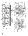
- FIG. 3a shows schematically and in an exploded view, which is only intended for explanatory purposes, the developments of: (I) the guide cams 15 spaced apart by the guide grooves 16 and their locking teeth 17 in the interior of the control head housing 5, (11) the guide region 9 'of the control sleeve 9 with the guide wedges 19 arranged thereon and the end toothing 21; and (111) the switching element 23 or the switching head 24 with the switching wedges 26 arranged thereon, including the oblique switching surfaces 27, and the stop plate 25.
- the housing containing the guide zone 13 will be described below in accordance with the arrangement of the mechanical parts in the control head and the related construction details 5 as "fixed" component (1), the control sleeve 9 designated as (11) as the actuating member, and the switching element 23 designated as (111) generally referred to as the control member.
- the (longer) tooth surface 17 'of the locking toothing 17 in the fixed component is referred to as the locking surface and the (shorter) tooth surface 17 "is referred to as the sliding surface.
- the tooth surfaces 17 ', 17 "and the inclined surfaces 21' are clearly effective here as cam follower surfaces.
- the spring symbols 28 are intended to indicate that the switching element 23 is always operationally under a pressure force exerted by the gas spring control rod 6 (FIGS. 1A, 1 B), which is supported on the housing 5 via the piston rod end 3.
- FIG. 3b The components of the control head symbolized and drawn apart in FIG. 3a with (I), (11) and (111) are shown in solid lines in FIG. 3b in the locked position of the gas spring piston rod 2 (FIGS. 1A, 1B), in which the control rod 6 is ejected.
- the switching element 23 is pushed into its inserted position in the locking mechanism 7.
- the switching wedge 26 In this position of the components 1, 11 and 111, the switching wedge 26 is caught in the guide groove 16, and its inclined surface 27 lies against the relative feed surface 21 'of the transport toothing 21 on the actuating member (control sleeve 9), which in turn via the Free ends 30 of the wedges 19 is supported on the stop shoulder 29 fixed to the housing.
- control head described above for the actuation of the control elements of a gas spring thus makes it possible, in a compact arrangement, to provide a latching mechanism 7 with which the two working methods of the gas spring can be selected by pulse actuation: piston rod "blocked” and piston rod “freely movable” can be selected. It is essential that the control head according to the invention can be firmly attached as a self-contained device on the piston rod 2 of the gas spring, and that the mode of operation of the gas spring selected by pulse actuation is maintained after the preselection has been made without external force or control action.
- This impulse actuation can of course take place in the manner of a push button actuation as well as by other actuation means such as piston-cylinder units or by electromechanical means.
- the anti-rotation lock of the control sleeve 9 could be achieved with a single guide wedge 19 or with a cross-sectional shape that generally deviates from around.
- the locking of the switching element 23 can be achieved with differently designed locking zones in the locking teeth 17 fixed to the housing. Finally, this can be profiled in such a way that when switching element 23 is shifted forward, it moves to the right.
Landscapes
- Fluid-Damping Devices (AREA)
Claims (11)
Priority Applications (1)
| Application Number | Priority Date | Filing Date | Title |
|---|---|---|---|
| AT81109614T ATE17436T1 (de) | 1980-11-21 | 1981-11-11 | Steuerkopf fuer gasfederbetaetigung, insbesondere fuer die sitzplattenverstellung an sitzmoebeln. |
Applications Claiming Priority (2)
| Application Number | Priority Date | Filing Date | Title |
|---|---|---|---|
| CH8633/80A CH652902A5 (de) | 1980-11-21 | 1980-11-21 | Steuerkopf zur betaetigung der steuerstange der ventilanordnung einer gasfeder. |
| CH8633/80 | 1980-11-21 |
Publications (3)
| Publication Number | Publication Date |
|---|---|
| EP0052832A2 EP0052832A2 (fr) | 1982-06-02 |
| EP0052832A3 EP0052832A3 (en) | 1983-04-20 |
| EP0052832B1 true EP0052832B1 (fr) | 1986-01-15 |
Family
ID=4342877
Family Applications (1)
| Application Number | Title | Priority Date | Filing Date |
|---|---|---|---|
| EP81109614A Expired EP0052832B1 (fr) | 1980-11-21 | 1981-11-11 | Tête de commande pour ressort pneumatique, notamment pour le réglage de sièges de meubles d'assise |
Country Status (4)
| Country | Link |
|---|---|
| EP (1) | EP0052832B1 (fr) |
| AT (1) | ATE17436T1 (fr) |
| CH (1) | CH652902A5 (fr) |
| DE (1) | DE3173534D1 (fr) |
Families Citing this family (13)
| Publication number | Priority date | Publication date | Assignee | Title |
|---|---|---|---|---|
| DE3325798C2 (de) * | 1983-07-16 | 1998-09-17 | Buerositzmoebelfabrik Friedric | Gasfeder zum Einstellen von Rückenlehnen von Stühlen, wie Bürodrehstühlen u.a. |
| DE3602441A1 (de) * | 1986-01-28 | 1987-07-30 | Bauer Fritz & Soehne Ohg | Laengenverstellbare gasfeder mit permanent-ausloese-einrichtung |
| CH676417A5 (fr) * | 1988-07-15 | 1991-01-31 | Giroflex Entwicklungs Ag | |
| DE4235435A1 (de) * | 1992-10-21 | 1994-04-28 | Martin Steifensand Sitzmoebel | Sitzträger für Sitzmöbel |
| DE19502649A1 (de) * | 1995-01-28 | 1996-08-01 | Stoll Kg Christof | Arretiermechanik für die neigbare Lehne eines Stuhles |
| US5577804A (en) * | 1995-06-30 | 1996-11-26 | Global Upholstery Company | Seat height adjustment mechanism for a chair |
| US5899530A (en) * | 1995-08-23 | 1999-05-04 | Global Upholstery Company | Control mechanism for a chair |
| IT242153Y1 (it) * | 1996-01-08 | 2001-06-04 | Alta Srl | Dispositivo di regolazione dell'inclinazione della seduta in sedie epoltroncine in genere |
| CA2207192C (fr) * | 1997-06-05 | 2000-10-10 | Global Upholstery Company | Fauteuil equipe d'un appareil vibro-masseur |
| ITTO980034A1 (it) | 1998-01-16 | 1999-07-16 | Miotto Int Comp | Dispositivo meccanico per il controllo della movimentazione sincrona d i sedile e schienale di una seduta. |
| US6845734B2 (en) * | 2002-04-11 | 2005-01-25 | Micron Technology, Inc. | Deposition apparatuses configured for utilizing phased microwave radiation |
| DE10353903A1 (de) | 2003-11-18 | 2005-06-16 | Suspa Holding Gmbh | Längenverstellbare Druckfeder |
| US20070102979A1 (en) | 2005-10-25 | 2007-05-10 | GLOBAL TOTAL OFFICE an Ontario limited partnership having GLOBAL UPHOLSTERY CO. | Adjustment mechanism for a chair and method for replacing a telescoping cylinder in a reconfigurable chair |
Family Cites Families (2)
| Publication number | Priority date | Publication date | Assignee | Title |
|---|---|---|---|---|
| GB930464A (en) * | 1960-04-05 | 1963-07-03 | Roll Tip England Ltd | Improvements in writing instruments |
| DE7831578U1 (de) * | 1978-10-23 | 1979-02-08 | Drabert Soehne Minden (Westf.), 4950 Minden | Verstelleinrichtung, insbesondere fuer gasfedern von sitzmoebeln |
-
1980
- 1980-11-21 CH CH8633/80A patent/CH652902A5/de not_active IP Right Cessation
-
1981
- 1981-11-11 DE DE8181109614T patent/DE3173534D1/de not_active Expired
- 1981-11-11 AT AT81109614T patent/ATE17436T1/de not_active IP Right Cessation
- 1981-11-11 EP EP81109614A patent/EP0052832B1/fr not_active Expired
Also Published As
| Publication number | Publication date |
|---|---|
| DE3173534D1 (en) | 1986-02-27 |
| ATE17436T1 (de) | 1986-02-15 |
| EP0052832A3 (en) | 1983-04-20 |
| EP0052832A2 (fr) | 1982-06-02 |
| CH652902A5 (de) | 1985-12-13 |
Similar Documents
| Publication | Publication Date | Title |
|---|---|---|
| EP0052832B1 (fr) | Tête de commande pour ressort pneumatique, notamment pour le réglage de sièges de meubles d'assise | |
| DE69600110T2 (de) | Verbesserungen an Verstell- und Bedienungsvorrichtungen von bewegenden und verformbaren Teilen eines Bürostuhls | |
| DE2948081A1 (de) | Laengeneinstellbares federelement | |
| DE69221004T2 (de) | Stufenlos verstellbarer Hubbegrenzer für hydraulischen Stellantrieb | |
| EP0179216B1 (fr) | Commande du dispositif de déclenchement d'un ressort pneumatique à longueur réglable | |
| DE602004011940T2 (de) | Fernsteuerung für schwere baumaschinen mit kolbenstangenstössel | |
| EP0394860A1 (fr) | Distributeur hydraulique | |
| DE2136724C3 (de) | Sitz mit verstellbarer Rückenlehne | |
| DE69712951T2 (de) | Mechanische Fernbedienungsanordnung mit Drucktastenschalter mit niedrigem Profil | |
| EP0772412A1 (fr) | Dispositif d'arret a systeme de freinage progressif | |
| DE4092384C2 (de) | 3-Positions-Stellglied | |
| DE2745886C2 (de) | Werkstückvorschubvorrichtung mit Differentialvorschub an Nähmaschinen | |
| DE3924309A1 (de) | Gasdruckfeder | |
| EP0259405B1 (fr) | Dispositif d'actionnement pour outil de rivetage | |
| DE102007020041A1 (de) | Tragarmarretierung | |
| DE3743944A1 (de) | Verstellbares federbein | |
| DE3325798C2 (de) | Gasfeder zum Einstellen von Rückenlehnen von Stühlen, wie Bürodrehstühlen u.a. | |
| DE4318516C2 (de) | Stuhl mit einer Vorrichtung zur Veränderung des Bewegungsspielraumes eines beweglichen Bauteiles | |
| CH664679A5 (de) | Hoehenverstellbare drehstuhl-stuetzsaeule. | |
| DE19649720C2 (de) | Linearantrieb | |
| DE1908689A1 (de) | Magnetschaltventil,insbesondere Mehrwegeventil mit Handbetaetigung | |
| DE4118806C2 (de) | Führungs-und Verstelleinrichtung für den Mastfuß eines Segelbrettes | |
| DE2710083C2 (de) | Bewegungsfühler | |
| DE2620495A1 (de) | Haupt-fernunterbrecher des stroms fuer fahrzeuge | |
| DE4426520C1 (de) | Arretierungsvorrichtung zum Feststellen eines einstellbaren ersten Elements gegenüber einem zweiten Element |
Legal Events
| Date | Code | Title | Description |
|---|---|---|---|
| PUAI | Public reference made under article 153(3) epc to a published international application that has entered the european phase |
Free format text: ORIGINAL CODE: 0009012 |
|
| AK | Designated contracting states |
Designated state(s): AT DE FR GB IT |
|
| PUAL | Search report despatched |
Free format text: ORIGINAL CODE: 0009013 |
|
| AK | Designated contracting states |
Designated state(s): AT DE FR GB IT |
|
| 17P | Request for examination filed |
Effective date: 19830527 |
|
| ITF | It: translation for a ep patent filed | ||
| GRAA | (expected) grant |
Free format text: ORIGINAL CODE: 0009210 |
|
| AK | Designated contracting states |
Designated state(s): AT DE FR GB IT |
|
| REF | Corresponds to: |
Ref document number: 17436 Country of ref document: AT Date of ref document: 19860215 Kind code of ref document: T |
|
| REF | Corresponds to: |
Ref document number: 3173534 Country of ref document: DE Date of ref document: 19860227 |
|
| ET | Fr: translation filed | ||
| R20 | Corrections of a patent specification |
Effective date: 19860407 |
|
| PLBE | No opposition filed within time limit |
Free format text: ORIGINAL CODE: 0009261 |
|
| STAA | Information on the status of an ep patent application or granted ep patent |
Free format text: STATUS: NO OPPOSITION FILED WITHIN TIME LIMIT |
|
| 26N | No opposition filed | ||
| PGFP | Annual fee paid to national office [announced via postgrant information from national office to epo] |
Ref country code: GB Payment date: 19901017 Year of fee payment: 10 |
|
| PGFP | Annual fee paid to national office [announced via postgrant information from national office to epo] |
Ref country code: FR Payment date: 19901029 Year of fee payment: 10 Ref country code: AT Payment date: 19901029 Year of fee payment: 10 |
|
| ITTA | It: last paid annual fee | ||
| PGFP | Annual fee paid to national office [announced via postgrant information from national office to epo] |
Ref country code: DE Payment date: 19910102 Year of fee payment: 10 |
|
| PG25 | Lapsed in a contracting state [announced via postgrant information from national office to epo] |
Ref country code: GB Effective date: 19911111 Ref country code: AT Effective date: 19911111 |
|
| GBPC | Gb: european patent ceased through non-payment of renewal fee | ||
| PG25 | Lapsed in a contracting state [announced via postgrant information from national office to epo] |
Ref country code: FR Effective date: 19920731 |
|
| PG25 | Lapsed in a contracting state [announced via postgrant information from national office to epo] |
Ref country code: DE Effective date: 19920801 |
|
| REG | Reference to a national code |
Ref country code: FR Ref legal event code: ST |