EP0053048A1 - Mehrkanal-Auffindungssystem mit vielfältiger Signalsendung - Google Patents
Mehrkanal-Auffindungssystem mit vielfältiger Signalsendung Download PDFInfo
- Publication number
- EP0053048A1 EP0053048A1 EP81401582A EP81401582A EP0053048A1 EP 0053048 A1 EP0053048 A1 EP 0053048A1 EP 81401582 A EP81401582 A EP 81401582A EP 81401582 A EP81401582 A EP 81401582A EP 0053048 A1 EP0053048 A1 EP 0053048A1
- Authority
- EP
- European Patent Office
- Prior art keywords
- signals
- emission
- receivers
- channels
- filter
- Prior art date
- Legal status (The legal status is an assumption and is not a legal conclusion. Google has not performed a legal analysis and makes no representation as to the accuracy of the status listed.)
- Granted
Links
Images


Classifications
-
- G—PHYSICS
- G01—MEASURING; TESTING
- G01S—RADIO DIRECTION-FINDING; RADIO NAVIGATION; DETERMINING DISTANCE OR VELOCITY BY USE OF RADIO WAVES; LOCATING OR PRESENCE-DETECTING BY USE OF THE REFLECTION OR RERADIATION OF RADIO WAVES; ANALOGOUS ARRANGEMENTS USING OTHER WAVES
- G01S7/00—Details of systems according to groups G01S13/00, G01S15/00, G01S17/00
- G01S7/52—Details of systems according to groups G01S13/00, G01S15/00, G01S17/00 of systems according to group G01S15/00
- G01S7/52003—Techniques for enhancing spatial resolution of targets
-
- G—PHYSICS
- G01—MEASURING; TESTING
- G01S—RADIO DIRECTION-FINDING; RADIO NAVIGATION; DETERMINING DISTANCE OR VELOCITY BY USE OF RADIO WAVES; LOCATING OR PRESENCE-DETECTING BY USE OF THE REFLECTION OR RERADIATION OF RADIO WAVES; ANALOGOUS ARRANGEMENTS USING OTHER WAVES
- G01S15/00—Systems using the reflection or reradiation of acoustic waves, e.g. sonar systems
- G01S15/88—Sonar systems specially adapted for specific applications
- G01S15/89—Sonar systems specially adapted for specific applications for mapping or imaging
Definitions
- the present invention relates to radar or sonar type echo detection systems in which an angular sector is the seat of electromagnetic or ultrasonic radiation emissions.
- the determination of the content of the sector results from the detection and detailed analysis of the signals reflected by the points of space which have been irradiated or insonified. This analysis provides data relating to the angular position and the distance from the targets. Using these data, an image representative of the area explored can be formed on the screen of a cathode ray tube.
- the distance of a target from the transmission-reception assembly is a function of the time elapsed between the transmission of a pulse and the reception of the corresponding echo.
- the angular position of the target may depend on the directivity of the transmission and / or reception means.
- the invention relates more particularly to echo detection systems in which the reception uses two receivers while the emission of the waves is ensured simultaneously by a set of radiating elements.
- this system can only provide a detailed image of the seabed by appropriate mechanical scanning.
- the present invention aims to overcome these drawbacks by offering the possibility of producing one-dimensional side or front grazing vision sonars as well as two-dimensional front vision sonars. These wide-field sonars make it possible to visualize the objects placed on the seabed. Without departing from the scope of the invention, mention may be made of medical imaging devices and non-destructive testing devices. To achieve this result with only two transducers as reception means, a diversified emission is adopted which consists in applying to the emission transducers differentiated excitations. Such an emission is said to be colored, because it assigns to each direction of the surveillance sector a law of illumination which is specific to it and which will characterize each echo according to its origin. The echo thus personalized can be perceived unequivocally by a set of reception channels. In addition, knowing a priori the diverse composition of the echo-producing radiation, it is possible to implement in the reception channels a correlation processing which provides greater resolution in terms of the processing of the angular data.
- the subject of the invention is a diversified transmission multi-channel detection system comprising transmission means using a set of adjacent radiating elements situated at the top of a predetermined angular sector and reception means using a pair of receivers. centered at said apex to capture the echoes coming from said sector, characterized in that said transmission means comprise means of simultaneous pulse excitation of said radiating elements assigning to each of them a form of signal allowing its identification as an element of said assembly; said receiving means comprise several receiving channels connected to said receivers by channel forming means which associate with each of said receiving channels a surface with constant path difference belonging to said angular sector; each of said receiving channels being connected to a filter adapted to the particular configuration of the echoes coming from this surface at constant path difference.
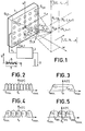
- FIG. 1 one can see a set 1 of emitting electromagnetic or ultrasonic waves making it possible to carry out detection by echoes of the radar or sonar type within the framework of a diversified emission.
- the radioelectric space or the marine propagation medium are related to a system of axes u, v, w whose origin O located at the center of the assembly 1 also represents the summit of an angular sector of surveillance.
- the emission assembly 1 comprises for example a matrix arrangement of radiating elements E 1,1 ⁇ E 1, n ... E m, 1 ... E m, n which, in the case of a sonar, are 1 electromechanical transducers capable of uniformifying the surveillance sector.
- Each radiating element of the assembly 1 is excited by an emission generator 2 which delivers a short pulse serving as a reference on an output 3.
- a set of connections 4 supplies each of the radiating elements of set 1 with impulse signals 5 the shape of which is represented in FIG. 1 to the left of the generator 2.
- the duration of the excitation signals 5 is T and their form S (t) is chosen so as to be able to identify each radiating element by the content which it emits .
- FIG. 1 shows a grid of space by r lines parallel to v and by s lines parallel to u.
- One of the points P i, k of the set of intersection rxs collects an emission composed of mxn discernible values.
- the polar coordinates 0 i, k , ⁇ i, k ' ⁇ i, k of the point P i, k determine with the coordinates of the radiating elements E m, n , a particular type of irradiation that can be calculated.
- the radiating elements can be arranged in any way, provided that they suitably sample the space and that identifiable codes can be used to predict and unambiguously recognize the combinations which represent this coloring of the space. .
- the signal S (P i, k ) only depends on the coordinates ⁇ i, k and ⁇ i, k .
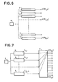
- FIG. 6 shows how a colored emission can be exploited on reception, while the wave receiver 6 does not have its own directivity.
- the echo signals are received by the receiver 6 which delivers a complex electrical signal to the input of a set of channels angular. Each angular channel is assigned to a direction from which the echo comes, which in FIG. 1 is the straight line passing through O and through P i, k .
- the receiver 6 can for example be located at point O and the receiver system of FIG. 6 can comprise rxs angular channels.
- Each angular channel in fact consists of a filter adapted 7 to the signals S (P i, k ) from which a correlation peak V (P i, k ) emerges.
- the adapted filter 7 of the angular path (0 i, k , ⁇ i, k ' ⁇ i, k ) is conditioned to react to the theoretical combination S (P i, k ) of the emissions produced in P i, k by the transmitter assembly. It can therefore be seen that the diversified emission results in a priori defining a colored space which confers on the system of FIG. 6 reception properties provided with angular selectivity.
- FIG. 7 illustrates an alternative embodiment of a receiver system provided with the same angular selectivity. Filters adapted to code C are supplied by the single receiver 6 which receives the echoes coming from the colored space.
- the filters adapted 8 to each of the transmitted codes used to excite the radiating elements of the emission assembly 1 separate each of the codes from the set of codes C 1,1 C 1,2 , ... C 1, n , ... C min .
- the correlation peaks delivered by the adapted filters 8 are then processed by an angular path formation circuit 9 which has mxn inputs connected to rxs outputs.
- the internal grouping of the circuit 9 for compensating for delays ⁇ ij of the codes which is used to form the channel V (P 1.1 ) has been represented by dashed lines. This channel is served by the signals from the mxn filters 8 added with delays which, added to the arrival delays at point P 1.1 of the elementary emissions, give a constant total delay.
- the receiver assembly of Figure 7 is equivalent to the assembly of Figure 6, but it better highlights the "imaging" function of the training circuit 9 which, although located in the reception section of an echo system, provides power separator and an energy contrast based on the geometry of the emission means.
- the forming circuit 9 is a circuit known as "transmission channel formation on reception”.
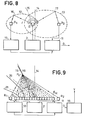
- FIG. 8 The diagram of such a system is illustrated in FIG. 8.
- the excitation of the single transmitter E is ensured by a generator 2 emitting for example pulses of duration T and of carrier frequency f.
- the receiver system comprises two receivers R 1 and R 2 located on either side of the transmitter E.
- a delay line 10 producing a delay T and connected to a summing circuit 11 forms an angular channel suitable for selecting echoes from of a hyperbolic tablecloth 15 which is a geometrical place with a path difference ⁇ for the receptions carried out by the two receivers R 1 and R 2 .
- the signal D leaving the summing circuit 11 is in fact associated with any echo coming from the sheet 15 but in the absence of coloring of the space by diversified emission, the signal D can be the cause of a serious confusion in locating echoes. To highlight this ambiguity, it suffices to consider two echoes coming from two distinct targets 16 and 17.
- the receiver R 1 receives the echo from the target 16 with a delay T after the transmission of a pulse by the transmitter E. This delay T1 defines a geometrical place in the form of an ellipsoid of revolution 12 having for foci R 1 and E.
- the receiver R 2 receives the echo of the target 17 with a delay T 2 after the emission of the same pulse by the emitter E.
- the invention proposes to carry out localization unequivocally using the technique of diversified transmission.
- the emission is obtained from a set of radiating elements E 1 , ... E M forming for example an alignment.
- the angular path formed is provided with a suitable filter 19.
- the generator 2 provides M separable excitations which produce at point P i a composite insonification which characterizes this point. We can calculate this insonification taking into account the codes used and the dotted routes to the point P i . This calculated insonification makes it possible to carry out a suitable filtering in the filter 19 so that the channel signal V obtained cannot correspond to other points of the colored space. The system is therefore no longer subject to the ambiguity of detection indicated in connection with FIG. 8.
- the two receivers R 1 R 2 make it possible to subdivide the space according to several hyperbolic layers 15, 20, 21 which correspond to constant differences in rate. It is therefore possible to form several angular paths by associating with each sheet a delay line 10 whose delay T corresponds to the path difference P i R 2 - P i R 1 .
- each hyperbolic layer whose trace 15 can be confused with the trace 18 of the asymptotic cone which has as its axis the line joining the receptors R 1 and R 2 , This cone is characterized by the angle ⁇ i which it forms with the plane 14 which is the plane of symmetry of the two receivers R 1 R 2 . If the emission takes place by a chain of radiating elements located according to the alignment of the two receivers, we can consider that a distant point P. receives an insonification which depends only on the angle ⁇ . and the prior choice of codes issued.
- the insonification must be adapted to each point of the hyperbolic layer considered.
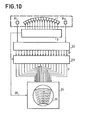
- Figure 10 gives an overview of a multi-channel detection system with diversified emission.
- each hyperbolic layer such as 15 (fig. 9) is a surface of revolution having as axis the line passing through two receivers.
- the coloring of the space is ensured by a generator 2 delivering to the radiating elements of the assembly 1 separable excitation signals, for example signals carrying orthogonal codes.
- the formation of several reception channels is ensured by a circuit 22 which contains several groupings performing the summation-delay function of the elements 10 and 11 of FIG. 9.
- the circuit 22 produces as many signals D that there are subdivisions in the angular sector to be monitored.
- Each signal D corresponds to a particular value of the delay ⁇ , therefore to a particular hyperbolic layer having the property of representing a geometrical place with constant difference in path.
- the signals D of reception channels formed by the circuit 22 are applied to a set of formation of transmission channels on reception 23 which is composed of elements similar to the channel element 19 of FIG. 9.
- Each element of adapted filtering transforms each signal D into a correlation peak V when the theoretical form imposed by the simultaneous and diversified transmission at the point of birth of the echo is in agreement with the form actually received by the two receivers.
- the set 23 therefore includes a generator of all the copies to which the diversified program has given rise in the surveillance sector. These copies are used for appropriate filtering at the level of each reception channel.
- This point P i belongs to a hyperbolic layer corresponding to a delay ⁇ i .
- the channel signal D i is obtained by synchronous addition of the two signals received by the two receivers R 1 and R 2 and its amplitude is 2 if the amplitude of a single signal is taken equal to 1.
- For another channel signal D k corresponds to another delay T k different from ⁇ i so that the two signals add up quadratically to obtain an amplitude of ⁇ 2.
- the difference between the optimal signal D i and the other channel signals is close to 3dB.
- the filter adapted to the signal S (P.), A single signal if P i is sufficiently far away, is the filter which processes the channel signal D i .
- This treatment is. equivalent to the synchronous addition of the M signals of the M transmitters coming from the point P i , and forming the signal S (P i ) so that an amplitude increase equal to M is obtained.
- FIG. 10 shows a device 24 for processing the signals V delivered by the circuit 23.
- This device comprises a screen 25 on which are displayed the echoes received in the surveillance sector.
- a link 26 transmits to the circuit 23 and to the operating device 24 a pulse indicative of the start of transmission. This pulse triggers the supply of copies to the various adapted filters of the set 23; it also serves as a reference for transcribing the round trip time into a distance measure.
- the image formed on the screen 25 can be sectorial to represent the angles and the distances from targets, but for a given distance, it can also be frontal when it represents the polar coordinates 0, f of FIG. 1.
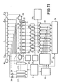
- FIG. 11 a detection system according to the invention, applicable in particular to lateral sonars.
- the transmission assembly 1 comprises an alignment of radiating elements E 1 , ... E M at the ends of which the two receivers R 1 and R 2 are placed.
- the transmission circuits make it possible to excite each radiating element by means of a separable code modulating for example a single carrier comprising a short pulse generator 2 which supplies a set of encoder circuits 27 having for impulse responses the codes sought.
- Each encoder circuit 27 excites a radiating element via a power amplifier 28.
- the codes chosen are for example of the P.S.K type (in English: Phase Shifting Keyed).
- circuits 2, 27 and 28 are replaced by a frequency generator of the synthesizer type.
- the formation of the receiving pathways is ensured by an elastic surface wave device.
- This device comprises a substrate 31 of piezoelectric material carrying two sets of electrodes 32 and 33 in the form of combs with interdigitated teeth. These sets of electrodes are located at the two ends of the substrate 31 and form electro-mechanical transducers emitting contraprogressive acoustic waves.
- the signals delivered by the receivers R 1 and R 2 are amplified by amplifiers not shown in FIG. 11.
- the amplified signals are applied to frequency changer circuits 29 with a local oscillator signal supplied by the generator 30. This frequency change is used to place the signals received in the operating band of the transducers 32 and 33.
- the transducer 32 radiates to the right a surface wave having the characteristics of the signal received by the receiver R 1 ; the transducer 33 radiates to the left a surface wave having the characteristics of the signal received by the receiver R 2 '
- a set of intermediate transducers 34 detects and adds with different delays the surface waves coming from the transducers 32 and 33.
- the transducers 34 therefore directly constitute the output members of the angular reception channels.
- the multiple outlet surface elastic wave delay line provides the dual benefit of simplicity and speed of processing. It is well suited for systems requiring delays of the order of ten or so. This is the case with lateral sonars and applications in the field of medical imaging.
- the distance separating the transducers 32 and 33 will be of the order of 7 cm when a substrate 31 made of lithium niobate is used.
- the reception channels are connected to frequency changer circuits 35 which receive a local oscillator signal produced by circuit 36. This second frequency change is intended to place the spectrum of channel signals as low as possible, in order to make simpler the adapted filtering operation.
- the outputs of the frequency changer circuits 35 are connected to the first inputs of correlation circuits 37. These correlation circuits receive by second inputs copies of the signals S (P.) delivered by a memory digital 40.
- a control circuit 39 supplies the memory 40 with the addresses of the copies.
- the generator 2 supplies a pulse to the address generator 39 to start the cycle of correlations.
- the copy is that of a near-field insonification, then it changes gradually until reaching the unchanging form which characterizes the insonification in distant field.
- FIG. 14 which shows the copy addresses K ,, K 2 , K 32 K 4 and K 5 going from the near field to the far field.
- the change of address changes less and less quickly to reach an asymptotic value, K 5 in FIG. 14.
- the role of the correlation circuits 37 is to recognize among all the forms of pulses received from the various points of the surveillance sector, that which characterizes a point P l situated on a hyperbolic sheet with determined path difference.
- the pulse durations T of the transmitted signals are between a few milliseconds and a few tens of milliseconds.
- each correlation circuit .37 is produced in a known manner by a correlator with charge transfer devices (CCD) whose operation is analogous to that of a shift register.
- CCD charge transfer devices
- Each correlator is adapted to a signal S (P i ) and for this signal, and only this, one obtains at the output, a signal having a correlation peak.
- the signal supplied to the CCD correlators is sampled at the frequency f HO supplied by a clock 38.
- the sampling frequency should be chosen at least twice the frequency of the input signal.
- the center frequency F c of the signal applied to the correlator is chosen to be as low as possible, that is to say close to B / 2, in order to obtain a number of stages K as reduced as possible.
- the CCD correlators are programmable and the applied copy evolves over time as shown
- a programmable CCD convolver has the structure of a transversal filter and includes a memory in which is loaded the copy, the CCD register itself, analog multipliers and a summator. To obtain the correlation from a convolver, you must invert the time variable for one of the two waveforms.
- the system of FIG. 11 is completed by an operating circuit 24 which makes it possible to obtain an image in mode B ( ⁇ , time).
- FIG. 11 shows a system in which a battery of correlating circuits 37 is used. It is also possible to sequentially multiplex over time the signals of the reception channels and to carry out the adapted filtering with a single correlating circuit, which amounts to substituting a serial processing to parallel processing.
- FIG. 12 Another alternative embodiment of the invention is illustrated in FIG. 12. It relates to applications such as ultrasound imaging in the medical field. Indeed, it uses convoluting devices with elastic surface waves of the channel signals which imply that the duration T of the pulse supplied to each radiating element is of the order of ten microseconds.
- the elastic surface wave devices generally operate with a carrier wave of a few tens of Megahertz.
- the signals delivered by the transducers 34 are sequentially multiplexed in time by a parallel-series converter 41.
- the channel signals D therefore arrive in series in time at the input of the convolver and we return to the first channel signal on each transmission. .
- the emission circuits have been left aside.
- the multiplexing rate is chosen taking into account the duration of the subsequent correlation processing.
- the correlation processing uses an elastic wave convolver, a detailed description of which is given in patent application No. 80 Il 225 filed in France on May 20, 1980 in the name of THOMSON-CSF.
- this convolver comprises a substrate 42 of piezoelectric material equipped with two end transducers 43 and 44. These transducers emit contraprogressive elastic waves which interact in a multiplicative manner.
- the collecting electrode 45 collects a signal representative of the convolution integral of the electrical signals
- the copy is returned over time which serves as an element of comparison to the signal transmitted by the converter 41 and applied to the transducer 43.
- the copies are stored by real and imaginary values in two memory areas 48 and 49.
- the two components of each copy are extracted from memory 48-49 by a control circuit 47 initialized by a pulse from the excitation generator 2.
- Converters digital-analog 50 and 51 placed under the control of a clock 52 supply sine and cosine multipliers contained in a modulator circuit 53 which receives a local oscillator signal coming from the oscillator 30.
- the signal delivered by the modulator circuit 53 is applied to transducer 4.
- the correlation peak available on output 46 has a frequency twice the frequency of the input signals.
- the time required to obtain the convolution function is of the order of the duration of the input signals.
- FIG. 13 one can see a system diagram implementing digital computing means.
- the signals delivered by the receivers R and R 2 are sampled and digitized at the frequency f HO of a clock 55 in two analog-digital converters 54.
- a microprocessor circuit 56 receives the digital signals coming from the converters 54 as well as an initialization pulse produced by the excitation generator 2. The operation of the microprocessor circuit 56 is timed by the clock 55.
- the microprocessor circuit 56 comprises in known manner, memories of RAM and PROM type, operators and input-output means. This circuit is programmed to digitally perform the formation of the reception D channels, and the appropriate filtering. The copies are stored in the memories of the microprocessor circuit and are called as the processing cycle proceeds.
- the operating assembly 24 receives the output signals from the microprocessor circuit 56 which can be directly used in a memory storing the samples represented of an image.
- the assembly 24 may also include digital-analog converters allowing the control of a cathode ray tube.
- the invention also applies to the formation of a two-dimensional front image of the sector to be monitored.
- the system has two interferometric bases.
- FIG. 15 we can see a first alignment oriented along v composed of the receptors R 1 and R 2 and a second alignment oriented along u composed of the receptors R 3 and R 4 .
- the transmission assembly 1 may consist of a matrix arrangement of radiating elements, but it may also be limited to a row and to a column of radiating elements arranged between the receivers along the axes u and v.
- the channel forming circuits 221 and 222 provide signals D and Du which are added together in a forming circuit 223 which delivers the signals D u, v which will be subjected to suitable filtering.
- the circuits 221, 222 and 223 can form only one.
- FIG. 16 To finish with a typical example of a system according to the invention, we see in FIG. 16 the arrangement of a sonar system with lateral vision.
- a carrier vehicle 59 towed by a cable 60 moves in the direction 58 near the seabed 61.
- a generally linear transmission assembly 1 and two receivers R and R 2 which form the base interferometric. Thanks to the angular paths formed, it is possible to make from the center O a directivity beam F which intercepts the seabed 61 along lines of width J perpendicular to direction 58.
- the hatched area Z corresponds to an angular path formed and at the projection distance a certain resolution r 2 is obtained for a certain angular width of the path.
- the transmitted frequency band B determines the distance resolution r 1 . Given the speed of the vehicle, the range and the resolution r 2 , several angular paths must be formed. By moving the vehicle 59, an image of the seabed is obtained.
- the encoder circuits on transmission generate 128 orthogonal 128-bit codes.
- the two receivers are advantageously directive.
- Their length is for example of the order of 50 mm.
- the proposed system greatly simplifies the reception circuits and makes it possible to obtain a given angular resolution with a reduced size of the transmission and reception means.
- this system operates in wide frequency band and makes it possible to obtain images in real time even at close range.
Landscapes
- Engineering & Computer Science (AREA)
- Radar, Positioning & Navigation (AREA)
- Remote Sensing (AREA)
- Physics & Mathematics (AREA)
- Computer Networks & Wireless Communication (AREA)
- General Physics & Mathematics (AREA)
- Acoustics & Sound (AREA)
- Measurement Of Velocity Or Position Using Acoustic Or Ultrasonic Waves (AREA)
Applications Claiming Priority (2)
| Application Number | Priority Date | Filing Date | Title |
|---|---|---|---|
| FR8023519A FR2493528A1 (fr) | 1980-11-04 | 1980-11-04 | Systeme de detection multivoies a emission diversifiee |
| FR8023519 | 1980-11-04 |
Publications (2)
| Publication Number | Publication Date |
|---|---|
| EP0053048A1 true EP0053048A1 (de) | 1982-06-02 |
| EP0053048B1 EP0053048B1 (de) | 1992-04-29 |
Family
ID=9247655
Family Applications (1)
| Application Number | Title | Priority Date | Filing Date |
|---|---|---|---|
| EP81401582A Expired - Lifetime EP0053048B1 (de) | 1980-11-04 | 1981-10-13 | Mehrkanal-Auffindungssystem mit vielfältiger Signalsendung |
Country Status (5)
| Country | Link |
|---|---|
| US (1) | US4458342A (de) |
| EP (1) | EP0053048B1 (de) |
| CA (1) | CA1189609A (de) |
| DE (1) | DE3177278D1 (de) |
| FR (1) | FR2493528A1 (de) |
Cited By (3)
| Publication number | Priority date | Publication date | Assignee | Title |
|---|---|---|---|---|
| US4829306A (en) * | 1987-08-31 | 1989-05-09 | Norges Teknisk-Naturvitenskapelige Forskningsråd | System for detection of objects with given, known characteristics against a background |
| US4831601A (en) * | 1986-10-31 | 1989-05-16 | Siemens Aktiengesellschaft | Apparatus for transmitting and receiving ultrasonic signals |
| EP0282265A3 (de) * | 1987-03-05 | 1989-11-15 | British Aerospace Public Limited Company | Bilderzeugungs-Systeme |
Families Citing this family (27)
| Publication number | Priority date | Publication date | Assignee | Title |
|---|---|---|---|---|
| US4841489A (en) * | 1985-12-27 | 1989-06-20 | Mitsubishi Denki Kabushiki Kaisha | Method of imaging an object by ultrasonic or electromagnetic waves |
| WO1987004256A1 (en) * | 1986-01-07 | 1987-07-16 | NORGES TEKNISK-NATURVITENSKAPELIGE FORSKNINGSRA^oD | System for detection of objects with given, known characteristics against a background |
| US4809249A (en) * | 1986-04-21 | 1989-02-28 | North American Philips Corporation | Apparatus for ultrasound flow mapping |
| US4855961A (en) * | 1986-07-31 | 1989-08-08 | Woods Hole Oceanographic Institute | Imaging apparatus |
| US5030956A (en) * | 1989-04-25 | 1991-07-09 | Murphy Quentin M | Radar tomography |
| DE4000698A1 (de) * | 1990-01-12 | 1991-07-18 | Hermesmeyer Alexander C Dipl I | Vorrichtung und verfahren zum erkennen der anwesenheit eines fahrzeugs mittels einer ultraschallvorrichtung |
| US5546356A (en) * | 1993-06-30 | 1996-08-13 | The United States Of America As Represented By The Secretary Of The Navy | Wide beam acoustic projector with sharp cutoff and low side lobes |
| US6009046A (en) * | 1995-03-02 | 1999-12-28 | Acuson Corporation | Ultrasonic harmonic imaging system and method |
| US5608690A (en) * | 1995-03-02 | 1997-03-04 | Acuson Corporation | Transmit beamformer with frequency dependent focus |
| US6005827A (en) | 1995-03-02 | 1999-12-21 | Acuson Corporation | Ultrasonic harmonic imaging system and method |
| US5678554A (en) * | 1996-07-02 | 1997-10-21 | Acuson Corporation | Ultrasound transducer for multiple focusing and method for manufacture thereof |
| US6027448A (en) * | 1995-03-02 | 2000-02-22 | Acuson Corporation | Ultrasonic transducer and method for harmonic imaging |
| US5891037A (en) * | 1997-12-18 | 1999-04-06 | Acuson Corporation | Ultrasonic Doppler imaging system with frequency dependent focus |
| US6160756A (en) * | 1998-06-15 | 2000-12-12 | Guigne International Limited | Seabed sonar matrix system |
| US6213947B1 (en) | 1999-03-31 | 2001-04-10 | Acuson Corporation | Medical diagnostic ultrasonic imaging system using coded transmit pulses |
| US6241674B1 (en) | 1999-03-31 | 2001-06-05 | Acuson Corporation | Medical ultrasound diagnostic imaging method and system with nonlinear phase modulation pulse compression |
| US7965794B2 (en) | 2000-05-05 | 2011-06-21 | Greenwich Technologies Associates | Method and apparatus for broadcasting with spatially diverse signals |
| US6823021B1 (en) | 2000-10-27 | 2004-11-23 | Greenwich Technologies Associates | Method and apparatus for space division multiple access receiver |
| CN100406851C (zh) * | 2003-06-04 | 2008-07-30 | 北京师范大学 | 一种侧扫声纳数据采集处理系统及其方法 |
| US9234978B2 (en) * | 2009-07-07 | 2016-01-12 | Westerngeco L.L.C. | Method for positioning the front end of a seismic spread |
| US8300499B2 (en) | 2009-07-14 | 2012-10-30 | Navico, Inc. | Linear and circular downscan imaging sonar |
| US8305840B2 (en) | 2009-07-14 | 2012-11-06 | Navico, Inc. | Downscan imaging sonar |
| US9268020B2 (en) * | 2012-02-10 | 2016-02-23 | Navico Holding As | Sonar assembly for reduced interference |
| US9354312B2 (en) | 2012-07-06 | 2016-05-31 | Navico Holding As | Sonar system using frequency bursts |
| JP5980636B2 (ja) * | 2012-09-20 | 2016-08-31 | 日本無線株式会社 | 物標検出装置 |
| FR3010799B1 (fr) * | 2013-09-13 | 2015-08-28 | Thales Sa | Systeme de detection et de localisation d'objets immerges flottant entre deux eaux tels que des mines a orins et procede associe |
| US10101479B2 (en) | 2014-08-14 | 2018-10-16 | Conocophillips Company | Marine deterministic notch compensation |
Citations (11)
| Publication number | Priority date | Publication date | Assignee | Title |
|---|---|---|---|---|
| GB946839A (en) * | 1961-07-21 | 1964-01-15 | Smith & Sons Ltd S | Improvements in and relating to echo sounding apparatus |
| US3268893A (en) * | 1963-10-08 | 1966-08-23 | Philco Corp | Angle measuring radar utilizing broad beam signal of known form and waveform recognition circuitry |
| US3458854A (en) * | 1968-07-08 | 1969-07-29 | Us Navy | Echo detection and ranging system |
| US3484737A (en) * | 1968-02-23 | 1969-12-16 | Raytheon Co | Acoustic mapping apparatus |
| US3676584A (en) * | 1970-07-13 | 1972-07-11 | Chris J Plakas | Echo coincidence ultrasonic scanning |
| US3680100A (en) * | 1970-12-15 | 1972-07-25 | Us Navy | Randomly phase coded antenna technique for search radar |
| US3716824A (en) * | 1969-10-17 | 1973-02-13 | Westinghouse Electric Corp | Side looking sonar apparatus |
| US3750152A (en) * | 1972-04-17 | 1973-07-31 | Gen Electric | Pulse-echo phase discriminator using deltic processing |
| US3771116A (en) * | 1972-01-12 | 1973-11-06 | Bendix Corp | Method and apparatus for imaging stationary and moving objects |
| US3875550A (en) * | 1973-07-16 | 1975-04-01 | Univ Leland Stanford Junior | Electronically focused acoustic imaging system and method |
| FR2368069A1 (fr) * | 1976-10-18 | 1978-05-12 | Bendix Corp | Systeme de visualisation sous-marine |
Family Cites Families (5)
| Publication number | Priority date | Publication date | Assignee | Title |
|---|---|---|---|---|
| US2368069A (en) * | 1943-05-28 | 1945-01-23 | Wright Tool & Forge Company | Procedure and equipment for forging or forming articles |
| US3427617A (en) * | 1959-04-21 | 1969-02-11 | Hazeltine Research Inc | Signal transmitting and receiving system |
| FR1329388A (fr) * | 1961-07-21 | 1963-06-07 | Smith & Sons Ltd S | Perfectionnements aux appareils de sondage par échos |
| FR1528578A (fr) * | 1965-11-19 | 1968-06-14 | Inst Francais Du Petrole | Méthode de détermination des courbes de niveau du fond sous-marin et dispositif pour sa mise en oeuvre |
| US3956749A (en) * | 1973-04-16 | 1976-05-11 | The United States Of America As Represented By The Secretary Of The Navy | Bearing measurement device for a portable attack warning radar |
-
1980
- 1980-11-04 FR FR8023519A patent/FR2493528A1/fr active Granted
-
1981
- 1981-10-13 EP EP81401582A patent/EP0053048B1/de not_active Expired - Lifetime
- 1981-10-13 DE DE8181401582T patent/DE3177278D1/de not_active Expired - Fee Related
- 1981-10-30 US US06/316,913 patent/US4458342A/en not_active Expired - Lifetime
- 1981-11-02 CA CA000389229A patent/CA1189609A/en not_active Expired
Patent Citations (11)
| Publication number | Priority date | Publication date | Assignee | Title |
|---|---|---|---|---|
| GB946839A (en) * | 1961-07-21 | 1964-01-15 | Smith & Sons Ltd S | Improvements in and relating to echo sounding apparatus |
| US3268893A (en) * | 1963-10-08 | 1966-08-23 | Philco Corp | Angle measuring radar utilizing broad beam signal of known form and waveform recognition circuitry |
| US3484737A (en) * | 1968-02-23 | 1969-12-16 | Raytheon Co | Acoustic mapping apparatus |
| US3458854A (en) * | 1968-07-08 | 1969-07-29 | Us Navy | Echo detection and ranging system |
| US3716824A (en) * | 1969-10-17 | 1973-02-13 | Westinghouse Electric Corp | Side looking sonar apparatus |
| US3676584A (en) * | 1970-07-13 | 1972-07-11 | Chris J Plakas | Echo coincidence ultrasonic scanning |
| US3680100A (en) * | 1970-12-15 | 1972-07-25 | Us Navy | Randomly phase coded antenna technique for search radar |
| US3771116A (en) * | 1972-01-12 | 1973-11-06 | Bendix Corp | Method and apparatus for imaging stationary and moving objects |
| US3750152A (en) * | 1972-04-17 | 1973-07-31 | Gen Electric | Pulse-echo phase discriminator using deltic processing |
| US3875550A (en) * | 1973-07-16 | 1975-04-01 | Univ Leland Stanford Junior | Electronically focused acoustic imaging system and method |
| FR2368069A1 (fr) * | 1976-10-18 | 1978-05-12 | Bendix Corp | Systeme de visualisation sous-marine |
Non-Patent Citations (1)
| Title |
|---|
| JOURNAL OF THE ACOUSTICAL SOCIETY OF AMERICA, vol. 68, no. 1, juillet 1980 New York, US B.B. LEE et al.: "Use of noise signals for multi-mode operation of phased arrays", pages 320-328 * |
Cited By (3)
| Publication number | Priority date | Publication date | Assignee | Title |
|---|---|---|---|---|
| US4831601A (en) * | 1986-10-31 | 1989-05-16 | Siemens Aktiengesellschaft | Apparatus for transmitting and receiving ultrasonic signals |
| EP0282265A3 (de) * | 1987-03-05 | 1989-11-15 | British Aerospace Public Limited Company | Bilderzeugungs-Systeme |
| US4829306A (en) * | 1987-08-31 | 1989-05-09 | Norges Teknisk-Naturvitenskapelige Forskningsråd | System for detection of objects with given, known characteristics against a background |
Also Published As
| Publication number | Publication date |
|---|---|
| DE3177278D1 (de) | 1992-06-04 |
| FR2493528B1 (de) | 1984-08-03 |
| FR2493528A1 (fr) | 1982-05-07 |
| CA1189609A (en) | 1985-06-25 |
| EP0053048B1 (de) | 1992-04-29 |
| US4458342A (en) | 1984-07-03 |
Similar Documents
| Publication | Publication Date | Title |
|---|---|---|
| EP0053048A1 (de) | Mehrkanal-Auffindungssystem mit vielfältiger Signalsendung | |
| EP0050060B1 (de) | Bilderzeugungssystem mit gleichzeitiger mehrfacher Aussendung | |
| EP2294452B1 (de) | Messverfahren und -Vorrichtung unter Verwendung von Wellenausbreitung | |
| EP0591061B1 (de) | Verfahren und Vorrichtung zur akustischen Prüfung mit Zeitumkehrsignalen | |
| US7089796B2 (en) | Time-reversed photoacoustic system and uses thereof | |
| EP0036794A1 (de) | Akustisches Abbildungssystem | |
| EP2872884A1 (de) | Verfahren zur verarbeitung von durch echolotung erfassten signalen sowie entsprechendes computerprogramm und echolotungsvorrichtung | |
| FR2717671A1 (fr) | Procédé et dispositif d'évaluation et de caractérisation des propriétés des os. | |
| EP0872742B1 (de) | Verfahren und Vorrichtung zur Verarbeitung von aus einer Volumenstruktur übertragenen oder gebeugten Signalen reflektierter Wellen zur Erkundung oder Analyse der Struktur | |
| JPS6218915B2 (de) | ||
| EP0543445A1 (de) | Untersuchungsgerät von Medien mittels Ultraschall-Echographie | |
| FR2628539A1 (fr) | Sonde, dispositif d'imagerie utilisant une telle sonde et procede mettant en oeuvre un tel dispositif | |
| EP3555659B1 (de) | Verfahren zur erfassung von ultraschallprüfsignalen sowie entsprechendes computerprogramm und ultraschallprüfvorrichtung | |
| FR3015742A1 (fr) | Procede de traitement de signaux issus d'une acquisition par sondage ultrasonore, programme d'ordinateur et dispositif de sondage a ultrasons correspondants | |
| EP0093057A1 (de) | Adaptive Filtereinrichtung für die von einem aktiven Sonar empfangenen Signale zur Nachhallunterdrückung | |
| CA2211419C (fr) | Procede et dispositif pour le traitement de signaux representatifs d'ondes reflechies ou transmises par une structure volumique en vue d'effectuer une exploration et une analyse de cette structure | |
| WO2015007992A1 (fr) | Procédé et dispositif de cartographie de milieux fibreux | |
| EP0718638A1 (de) | Verfahren zum Entdecken von Gegenständen in der Bodenfläche oder zum Bestimmen der Ausbreitungsmerkmale einer akustischen Welle im Boden und Vorrichtung dafür | |
| EP4189380B1 (de) | Verfahren zur erkennung von diskontinuitäten und system zur implementierung dieses verfahrens | |
| RU2319976C1 (ru) | Способ поиска передатчиков сложных сигналов | |
| FR2901365A1 (fr) | Sonar frontal ameliore | |
| FR2737576A1 (fr) | Procede et dispositif d'aide a la simulation du fouillis de sol pour un radar a impulsions | |
| EP2044456A2 (de) | System und verfahren zur dreidimensionalen ortsbestimmung eines objekts in einem volumen | |
| FR2815724A1 (fr) | Systeme d'echographie et sonde acoustique pour un tel systeme | |
| FR2629213A1 (fr) | Radar a balayage de phase |
Legal Events
| Date | Code | Title | Description |
|---|---|---|---|
| PUAI | Public reference made under article 153(3) epc to a published international application that has entered the european phase |
Free format text: ORIGINAL CODE: 0009012 |
|
| AK | Designated contracting states |
Designated state(s): BE DE GB IT NL |
|
| 17P | Request for examination filed |
Effective date: 19820621 |
|
| RAP3 | Party data changed (applicant data changed or rights of an application transferred) |
Owner name: THOMSON-CSF |
|
| GRAA | (expected) grant |
Free format text: ORIGINAL CODE: 0009210 |
|
| AK | Designated contracting states |
Kind code of ref document: B1 Designated state(s): BE DE GB IT NL |
|
| ITF | It: translation for a ep patent filed | ||
| REF | Corresponds to: |
Ref document number: 3177278 Country of ref document: DE Date of ref document: 19920604 |
|
| GBT | Gb: translation of ep patent filed (gb section 77(6)(a)/1977) | ||
| PGFP | Annual fee paid to national office [announced via postgrant information from national office to epo] |
Ref country code: BE Payment date: 19920925 Year of fee payment: 12 |
|
| PLBE | No opposition filed within time limit |
Free format text: ORIGINAL CODE: 0009261 |
|
| STAA | Information on the status of an ep patent application or granted ep patent |
Free format text: STATUS: NO OPPOSITION FILED WITHIN TIME LIMIT |
|
| 26N | No opposition filed | ||
| PG25 | Lapsed in a contracting state [announced via postgrant information from national office to epo] |
Ref country code: NL Effective date: 19930501 |
|
| NLV4 | Nl: lapsed or anulled due to non-payment of the annual fee | ||
| ITTA | It: last paid annual fee | ||
| PG25 | Lapsed in a contracting state [announced via postgrant information from national office to epo] |
Ref country code: BE Effective date: 19931031 |
|
| BERE | Be: lapsed |
Owner name: THOMSON-CSF Effective date: 19931031 |
|
| PGFP | Annual fee paid to national office [announced via postgrant information from national office to epo] |
Ref country code: GB Payment date: 19970918 Year of fee payment: 17 Ref country code: DE Payment date: 19970918 Year of fee payment: 17 |
|
| PG25 | Lapsed in a contracting state [announced via postgrant information from national office to epo] |
Ref country code: GB Free format text: LAPSE BECAUSE OF NON-PAYMENT OF DUE FEES Effective date: 19981013 |
|
| GBPC | Gb: european patent ceased through non-payment of renewal fee |
Effective date: 19981013 |
|
| PG25 | Lapsed in a contracting state [announced via postgrant information from national office to epo] |
Ref country code: DE Free format text: LAPSE BECAUSE OF NON-PAYMENT OF DUE FEES Effective date: 19990803 |
|
| APAH | Appeal reference modified |
Free format text: ORIGINAL CODE: EPIDOSCREFNO |