EP0718638A1 - Verfahren zum Entdecken von Gegenständen in der Bodenfläche oder zum Bestimmen der Ausbreitungsmerkmale einer akustischen Welle im Boden und Vorrichtung dafür - Google Patents
Verfahren zum Entdecken von Gegenständen in der Bodenfläche oder zum Bestimmen der Ausbreitungsmerkmale einer akustischen Welle im Boden und Vorrichtung dafür Download PDFInfo
- Publication number
- EP0718638A1 EP0718638A1 EP95402576A EP95402576A EP0718638A1 EP 0718638 A1 EP0718638 A1 EP 0718638A1 EP 95402576 A EP95402576 A EP 95402576A EP 95402576 A EP95402576 A EP 95402576A EP 0718638 A1 EP0718638 A1 EP 0718638A1
- Authority
- EP
- European Patent Office
- Prior art keywords
- transducer
- transducers
- standard
- propagation
- signal
- Prior art date
- Legal status (The legal status is an assumption and is not a legal conclusion. Google has not performed a legal analysis and makes no representation as to the accuracy of the status listed.)
- Granted
Links
- 238000000034 method Methods 0.000 title claims abstract description 38
- 238000001514 detection method Methods 0.000 title claims abstract description 30
- 238000012545 processing Methods 0.000 claims abstract description 16
- 239000011159 matrix material Substances 0.000 claims description 15
- 239000002689 soil Substances 0.000 claims description 14
- 230000004807 localization Effects 0.000 claims description 12
- 238000013507 mapping Methods 0.000 claims description 11
- 238000002592 echocardiography Methods 0.000 claims description 10
- 230000002123 temporal effect Effects 0.000 abstract description 2
- 230000006870 function Effects 0.000 description 7
- 238000004364 calculation method Methods 0.000 description 5
- 230000015654 memory Effects 0.000 description 5
- 239000000463 material Substances 0.000 description 4
- 238000010586 diagram Methods 0.000 description 3
- 238000002059 diagnostic imaging Methods 0.000 description 2
- 230000005284 excitation Effects 0.000 description 2
- 238000009434 installation Methods 0.000 description 2
- 238000005259 measurement Methods 0.000 description 2
- 230000001537 neural effect Effects 0.000 description 2
- 238000012800 visualization Methods 0.000 description 2
- 206010028980 Neoplasm Diseases 0.000 description 1
- 230000009471 action Effects 0.000 description 1
- 230000004913 activation Effects 0.000 description 1
- 238000013459 approach Methods 0.000 description 1
- BJQHLKABXJIVAM-UHFFFAOYSA-N bis(2-ethylhexyl) phthalate Chemical compound CCCCC(CC)COC(=O)C1=CC=CC=C1C(=O)OCC(CC)CCCC BJQHLKABXJIVAM-UHFFFAOYSA-N 0.000 description 1
- 238000009933 burial Methods 0.000 description 1
- 238000004422 calculation algorithm Methods 0.000 description 1
- 239000000919 ceramic Substances 0.000 description 1
- 238000006243 chemical reaction Methods 0.000 description 1
- 239000004020 conductor Substances 0.000 description 1
- 230000006378 damage Effects 0.000 description 1
- 230000001419 dependent effect Effects 0.000 description 1
- 230000000694 effects Effects 0.000 description 1
- 230000000977 initiatory effect Effects 0.000 description 1
- 238000003780 insertion Methods 0.000 description 1
- 230000037431 insertion Effects 0.000 description 1
- 238000012804 iterative process Methods 0.000 description 1
- 239000000696 magnetic material Substances 0.000 description 1
- 238000012067 mathematical method Methods 0.000 description 1
- 238000012986 modification Methods 0.000 description 1
- 230000004048 modification Effects 0.000 description 1
- 230000008569 process Effects 0.000 description 1
- 230000000717 retained effect Effects 0.000 description 1
- 238000005070 sampling Methods 0.000 description 1
Images


Classifications
-
- F—MECHANICAL ENGINEERING; LIGHTING; HEATING; WEAPONS; BLASTING
- F41—WEAPONS
- F41H—ARMOUR; ARMOURED TURRETS; ARMOURED OR ARMED VEHICLES; MEANS OF ATTACK OR DEFENCE, e.g. CAMOUFLAGE, IN GENERAL
- F41H11/00—Defence installations; Defence devices
- F41H11/12—Means for clearing land minefields; Systems specially adapted for detection of landmines
-
- G—PHYSICS
- G01—MEASURING; TESTING
- G01S—RADIO DIRECTION-FINDING; RADIO NAVIGATION; DETERMINING DISTANCE OR VELOCITY BY USE OF RADIO WAVES; LOCATING OR PRESENCE-DETECTING BY USE OF THE REFLECTION OR RERADIATION OF RADIO WAVES; ANALOGOUS ARRANGEMENTS USING OTHER WAVES
- G01S15/00—Systems using the reflection or reradiation of acoustic waves, e.g. sonar systems
- G01S15/87—Combinations of sonar systems
-
- G—PHYSICS
- G01—MEASURING; TESTING
- G01S—RADIO DIRECTION-FINDING; RADIO NAVIGATION; DETERMINING DISTANCE OR VELOCITY BY USE OF RADIO WAVES; LOCATING OR PRESENCE-DETECTING BY USE OF THE REFLECTION OR RERADIATION OF RADIO WAVES; ANALOGOUS ARRANGEMENTS USING OTHER WAVES
- G01S15/00—Systems using the reflection or reradiation of acoustic waves, e.g. sonar systems
- G01S15/88—Sonar systems specially adapted for specific applications
- G01S15/89—Sonar systems specially adapted for specific applications for mapping or imaging
-
- G—PHYSICS
- G01—MEASURING; TESTING
- G01S—RADIO DIRECTION-FINDING; RADIO NAVIGATION; DETERMINING DISTANCE OR VELOCITY BY USE OF RADIO WAVES; LOCATING OR PRESENCE-DETECTING BY USE OF THE REFLECTION OR RERADIATION OF RADIO WAVES; ANALOGOUS ARRANGEMENTS USING OTHER WAVES
- G01S7/00—Details of systems according to groups G01S13/00, G01S15/00, G01S17/00
- G01S7/52—Details of systems according to groups G01S13/00, G01S15/00, G01S17/00 of systems according to group G01S15/00
- G01S7/52004—Means for monitoring or calibrating
Definitions
- the field of the present invention is that of methods and devices making it possible to detect objects or else to determine the propagation characteristics of an acoustic wave in the ground of a terrain area.
- the invention relates more particularly to a method and a device for detecting mines buried in an area of land.
- Methods and devices are known for mine detection using magnetic means. These devices use a generator and a conductive coil. When a conductive material is in the vicinity of the coil, the current flowing in the latter is disturbed and a detection signal is supplied by an electronic processing circuit.
- the detector may be activated by magnetic objects other than the mines sought, which causes false alarms which further slow down demining operations.
- This method uses a certain number of acoustic transducers (transmitters / receivers) and it makes it possible to focus in an almost automatic way an acoustic beam on an object whose position is unknown.
- Such a method is particularly well suited to medical imaging and makes it possible to detect the position of stones or tumors in the human body.
- the transducers are placed at reduced distances (less than 200 mm) from the objects to be detected and the speed of propagation of the sound waves remains substantially the same in all directions of the area to be explored.
- this method is unsuitable for detecting objects in the ground, especially in large areas (of the order of 5 to 10,000 m 2 ).
- the method according to the invention makes it possible to ensure acoustic detection of objects (in particular mines) distributed in an area of land. It is therefore not dependent on the nature of the materials, magnetic or not, constituting the objects.
- the method according to the invention can be implemented remotely from the objects to be detected, which makes it possible to increase the safety of the operation when the objects are mines.
- the method according to the invention makes it possible to detect objects in an area of land of large dimensions without imposing a passage on the ground with the detection means, which further increases security.
- the method according to the invention also allows remote activation or destruction of the latter.
- the invention also relates to a device allowing the implementation of this process.
- This device ensures reliable and remote detection for large areas of land.
- the known methods envisage the use of acoustic transmitters and receivers arranged at spaced points. They have the drawback of being complex to implement, due to the distance between transmitters and receivers and the synchronization problems which result therefrom.
- the invention proposes a global approach to both the problems of determining the characteristics of the soil and the problems of detecting buried objects.
- the global inventive concept proposed implements the principle of the temporal reversal of the acoustic waves which makes it possible, on the one hand to ensure the realization of a fast and precise cartography of the acoustic characteristics of the ground and on the other hand to detect in a sure way objects buried even in large areas.
- the first object to be treated is chosen by time reversal by an analysis of the shape waves according to the different return echoes received by each transducer, followed by a comparison of these shape waves with a library of signatures characteristic of the main objects sought.
- the first object is identified after execution of the k time reversals by an analysis of the shape waves according to the different echo signals received by each transducer and comparison of these shape waves to a library of signatures characteristic of the main objects sought.
- At least one other acoustic signal is sent to it having the form of that memorized at the end of the last time reversal, amplified signal and the intensity of which is sufficient to move or vibrate the object.
- the invention also relates to a device for determining the propagation characteristics of an acoustic wave in the ground of a terrain area or for detecting objects, and in particular mines distributed in a terrain area, characterized device in that it comprises at least one row of acoustic transducers connected to processing electronics, each transducer being carried by a support intended to be pressed in or applied to the ground.
- This device may include at least one row of standard targets which have the form of stakes that can be driven into the ground or even standard targets which have a buried part having substantially the shape of an object that is sought in the field.
- the device will advantageously include means for measuring the different distances between transducer supports and standard targets.
- These distance measurement means may include at least one laser rangefinder carried by at least one transducer support and / or at least one standard target.
- the transducer supports and / or the standard targets are set up individually in the field, radio link means being provided between each transducer support and / or standard target and at least a portion processing electronics to allow synchronization of transducer emissions.
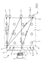
- a land area delimited here by dashed lines, contains a number of objects 2, which are buried mines.
- a device 3 for detecting (or determining acoustic wave propagation characteristics in the ground) according to the invention comprises a certain number (n) of acoustic transducers distributed along a line 4 (the various transducers are numbered T1, T2, ... Ti, ... Tn). The transducers are placed along a first border F1 of zone 1.
- the transducers are constituted in a conventional manner by piezoelectric ceramic plates or by electromagnetic transducers.
- the transducers are separated by a step for example of the order of 500mm.
- a step for example of the order of 500mm.
- the transducers are arranged so that they can emit and receive acoustic waves in the ground. They are carried for example by supports in the form of stakes which allow their installation at an optimal depth (for example the usual depth of installation of the mines, that is to say from 200 to 300mm), or even the depth at which one seeks to study the characteristics of acoustic propagation.
- the transducers could also be carried by supports simply placed on the ground. In this case, the support keeps the transducer pressed against the ground. The acoustic waves are then emitted on the surface but they however propagate in a layer of ground whose thickness is of the order of 200 to 300mm, which authorizes the detection of mines which are usually buried at such depths.
- the transducers T1 to Tn are connected to an electronic processing unit 5 which includes a number of channels 6.1, 6.2, ... 6.i, ..6.n (one channel per transducer) and a command and control assembly common 7.
- the device according to the invention also comprises m standard targets, numbered in FIG. C1, C2, ... Cj, ... Cm and distributed along a line and along a second border F2 of the area.
- Standard targets for example, have the form of stakes driven into the ground to an appropriate depth. It will thus be possible to choose a depth substantially equal to that of the insertion of the stakes carrying the transducers, or even equal to that at which objects must be sought or at which the characteristics of the ground must be measured.
- a variable unfocused frequency for example by means of a swept frequency generator
- the frequencies of use most often vary between 10 Hz and 100 kHz depending on the nature of the soil.
- this mapping is carried out by implementing the method of focusing sound waves by time reversal of the signals.
- the number of time reversals depends on the nature of the ground, we can prefer an odd number of reversals in order to have a symmetry of the wavefront of the signals obtained.
- the focalization obtained is sufficient when the echo returned by a target is sufficiently discriminated from the others, for example when its amplitude is at least three times greater than that of the others.
- the distances Dij are measured with appropriate means, for example a laser range finder mounted on each support carrying the transducer and oriented successively towards each standard target.
- Each propagation time tij is measured as being equal to half the duration separating the emission of a signal and the return of the echo corresponding to the target.
- the acoustic waves are focused on each standard target by choosing an appropriate time window.
- the position of the standard targets is known with precision, it is therefore easy to choose the echoes coming from a given target, and to define the time window with respect to these echoes.
- targets for the detection of mines, targets will be adopted comprising a cylinder approximately 200mm in diameter and 100mm high (usual dimensions of anti-tank mines), a cylinder which will be buried at the usual depth for mines. See in particular Figure 4c described below.
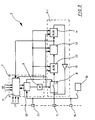
- FIG. 3 represents an embodiment of an electronic processing unit 5 making it possible to implement the above method.
- This processing electronics includes processing channels 6.1, .., 6.i, .. 6.n and a common control unit 7.
- Each transducer Ti is associated with a processing channel 6.i (only one channel is shown here).
- Each channel 6.i comprises a sampler 8 which is intended to supply analog samples of the signal received by the transducer Ti at the frequency of a clock 9 of the control assembly 7.
- the sampling frequency given by the clock will depend on the optimal working frequency. It will preferably be greater than R / LxVij, expression in which R is the resolution or the number of points of the signal (100 for example), L is the main dimension of the smallest object sought and Vij the average propagation speed of the waves in ground.
- the time intervals during which the sampler works are determined by a timer 10 (also integral with the control assembly 7).
- the timer allows you to define the time window in which the echo signals will be considered by the different samplers.
- the duration of the time window will be chosen to be sufficient for each transducer to receive a return echo corresponding to the chosen standard target.
- this time window was determined after reception of the first echo signals, so as to frame all the desired maxima corresponding to the standard target.
- the time window or windows will be chosen by the user by an action on the timer 10 by means of a computer 11 (also integral with the control assembly 7) and provided with an appropriate interface with the user (keyboard , screen ).
- the sampler 8 is followed by an analog / digital converter 12. In general, a conversion on ten bits is sufficient to represent the echoes satisfactorily.
- the words representative of a sample are stored in a memory 13, organized in a waiting stack (of the last in-first out type).
- This memory will be chosen sufficient to store all the samples received during the duration of the time window.
- the timer 10 is also designed to cause the emission of a wavefront returned after a short time after the end of reception of the received echo (a few milliseconds).
- Each channel 6.i comprises to allow the retransmission a digital / analog converter 14, optionally followed by an amplifier 15 whose output drives the associated transducer Ti.
- An excitation circuit 16 makes it possible to apply to one or more of the transducers the short, unfocused initial pulse at the optimum frequency.
- the circuit 16 is shown connected to all the transducers. In fact, means (not shown) are provided for connecting it to one or more transducers of the user's choice.
- Such an electronic processing unit 5 is described in patents FR2642640 and FR2696573.
- the computer 11 will be connected to all the channels 6.i associated with the different transducers. It is the same for the clock 9 and the timer 10, the synchronization of the different channels being essential to ensure the proper functioning of the focusing device by time reversal of the echoes.
- the connections connecting the command and control assembly 7 to the various processing channels 6.i have been shown diagrammatically at 17.
- the computer 11 also receives (connections 18) the information provided by the different rangefinder (s).
- It also contains memories or registers making it possible to store a matrix containing the different relative distances Dij measured between each transducer Ti and each standard target Cj.
- the computer After carrying out the focusing operations on the different targets Cj (j varying from 1 to m), the computer therefore stores in memory all the values of the average propagation speeds Vij along the different directions connecting each transducer to each standard target.
- This matrix of propagation characteristics is used by the method according to the invention to carry out a detection of buried objects and in particular of mines.
- the working frequency used is still the optimal frequency determined previously.
- the time window is chosen from the first echo signal received by the device.
- Such a library is easy to establish by carrying out a calibration of the device on a known ground in which the various known mines which one may have to search will be buried successively.
- the comparison between the shape waves and the signature library will preferably be made by means of neural circuits.
- Such circuits are known to those skilled in the art and they make it possible to quickly perform the shape recognition calculations.
- k successive time reversals of the signals received by the transducers are carried out in order to focus the detection on the first mine and the signals reflected at the end of the last time reversal are stored.
- transducers correspond in principle to those located closest to the first mine.
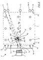
- FIG. 2 is similar to FIG. 1 and it shows two transducers Tx and Ty which have been retained following the focusing of the detection on a first mine.
- the processing electronics 5 determines, for each of the transducers selected (Tx and Ty), different potential points or localization zones for the mine along the different directions Dxj, Dyj which join each transducer Tx, Ty considered to a standard target. Cj.
- This determination will be made by calculating the different distances dxj, dyj (j varying from 1 to m) along the directions Dxj, Dyj.
- This calculation makes it possible to determine, associated with each Tx or Ty transducer, a certain number of points, respectively: Px1, Px2, ... Pxj, ... Pxm, and Py1, Py2, ... Pyj, ... Pym .
- the points Pxj associated with the transducer Tx form a curve Kx, those associated with the transducer Ty form a curve Ky.
- the potential location of the first target will be at the intersection of the Kx and Ky curves, or at the level of an area for which the distance between the curves is minimum.
- the computer 11 will ensure the determination of the curves Kx and Ky, for example by implementing known mathematical methods such as the polynomial approximation.
- adjoining Tx and Ty transducers will be chosen.
- non-contiguous transducers or more than two transducers may also be used.
- a location area of the first mine could then be defined by the area containing the different intersections of the K curves two by two.
- a target is potentially not at a point Pxj, Pyj on a direction Dxj or Dyj but in a zone Z (hatched on the figure ), which contains the point considered and has a minimum surface.
- a visualization screen will facilitate the exploitation of the data by the user (visualization of the curves and / or localization zones with indication of their coordinates).
- the computer 11 also performs the comparison of the signals received with the mine library and it will therefore include the memories containing the signature library as well as the necessary neural circuits.
- the method according to the invention After detection and localization of a first mine, the method according to the invention will be repeated so as to detect and locate another mine. Another time window will be chosen for this.
- FIG. 4a shows a stake 19.i which carries at its lower part a transducer Ti and at its upper part a housing 20.i which contains the treatment path 6.i associated with the transducer Ti carried by the stake.
- the box 20.i also contains a radio transmitter / receiver and it carries an antenna 21.i as well as an angularly adjustable laser rangefinder 22.i.
- the housing 20.i will preferably be removable from the stake 19 in order to allow the latter to be pushed in. Electrical connection means will be provided between the transducer Ti and the housing 20.i which will in particular include a connector 23.i.
- FIG. 4b shows a standard target Cj which has the shape of a stake. It carries at its upper part a reflective strip 24.j which facilitates its location by the various laser rangefinders 22.i.
- FIG. 4c shows another type of standard target Cj which comprises a stake carrying at its upper part a reflecting strip 24.j and at its lower part a cylinder 27 having the dimensions of a real mine which it is desired to search in the field .
- the same material will be chosen to make the cylinder as that of the mines sought.
- Figure 5 shows the implementation of the device according to the invention.
- the stakes 19.1 carrying the transducers Ti are placed individually along the first border F1 of the area of terrain 1.
- the standard targets Cj are driven into the ground along the second border F2.
- the spacings of the different stakes and different targets were measured with precision when they were set up, for example with laser rangefinders.
- a control module 25 is placed at a distance from the terrain area 1. It also contains a radio transmitter / receiver coupled to an antenna 26, it is connected to a control screen and to a control keyboard.
- the control module contains part of the processing electronics. It performs the common command and control assembly function 7 described above with reference to FIG. 3. Thus it will contain a clock 9, a timer 10 and a computer 11.
- a clock and a common timer as well as a radio link makes it possible to synchronize the emissions of the different transducers even for a large number of these and for large distances.
- a decoder will transform the radio information sent by the different stakes into information usable by the computer.
- the laser range finders not on the transducer stakes but on the target stakes Cj.
- the stakes 19.i will then carry a reflective strip to facilitate their location and the target stakes Cj will be fitted with radio transmitters / receivers to ensure their connection to the control module 25.
- each standard target Cj with a receiver of the acoustic signals emitted by the transducers Ti.
- each standard target Cj can be provided with an emitter of acoustic signals and the various transducers Ti can be used as receivers.
- radio link means will be provided between the transducers and / or the targets and the control module 25.
- the various calculations will be carried out by the computer 11 which is placed therein.
- the invention has been described in the context of its application to the detection of landmines. It is of course applicable to the detection of buried objects or to the identification of soil heterogeneities.
Landscapes
- Engineering & Computer Science (AREA)
- Radar, Positioning & Navigation (AREA)
- Remote Sensing (AREA)
- Physics & Mathematics (AREA)
- Computer Networks & Wireless Communication (AREA)
- General Physics & Mathematics (AREA)
- General Engineering & Computer Science (AREA)
- Acoustics & Sound (AREA)
- Geophysics And Detection Of Objects (AREA)
- Measurement Of Velocity Or Position Using Acoustic Or Ultrasonic Waves (AREA)
Applications Claiming Priority (2)
| Application Number | Priority Date | Filing Date | Title |
|---|---|---|---|
| FR9415338 | 1994-12-20 | ||
| FR9415338A FR2728352A1 (fr) | 1994-12-20 | 1994-12-20 | Procede de detection d'objets repartis dans une zone de terrain ou de determination des caracteristiques de propagation d'une onde acoustique dans le sol et dispositif mettant en oeuvre de tels procedes |
Publications (2)
| Publication Number | Publication Date |
|---|---|
| EP0718638A1 true EP0718638A1 (de) | 1996-06-26 |
| EP0718638B1 EP0718638B1 (de) | 2000-03-08 |
Family
ID=9470002
Family Applications (1)
| Application Number | Title | Priority Date | Filing Date |
|---|---|---|---|
| EP95402576A Expired - Lifetime EP0718638B1 (de) | 1994-12-20 | 1995-11-17 | Verfahren zum Entdecken von Gegenständen in der Bodenfläche oder zum Bestimmen der Ausbreitungsmerkmale einer akustischen Welle im Boden und Vorrichtung dafür |
Country Status (5)
| Country | Link |
|---|---|
| US (1) | US5615174A (de) |
| EP (1) | EP0718638B1 (de) |
| DE (1) | DE69515444T2 (de) |
| FR (1) | FR2728352A1 (de) |
| NO (1) | NO955165L (de) |
Families Citing this family (9)
| Publication number | Priority date | Publication date | Assignee | Title |
|---|---|---|---|---|
| FR2728354A1 (fr) * | 1994-12-20 | 1996-06-21 | Giat Ind Sa | Procede de detection d'objets repartis dans une zone de terrain et dispositif mettant en oeuvre un tel procede |
| US5936233A (en) * | 1998-02-26 | 1999-08-10 | The Curators Of The University Of Missouri | Buried object detection and neutralization system |
| AU2003294296A1 (en) * | 2002-11-12 | 2004-09-06 | General Dynamics Advanced Information Systems | A method and system for in-air ultrasonic acoustical detection and characterization |
| US20080134869A1 (en) * | 2005-12-22 | 2008-06-12 | Stuart Owen Goldman | Forced premature detonation of improvised explosive devices via radiated electromagnetic energy |
| US7698981B2 (en) * | 2005-12-22 | 2010-04-20 | Alcatel-Lucent Usa Inc. | Forced premature detonation of improvised explosive devices via noise print simulation |
| US20080134871A1 (en) * | 2005-12-22 | 2008-06-12 | Stuart Owen Goldman | Forced premature detonation of improvised explosive devices via laser energy |
| US20080134870A1 (en) * | 2005-12-22 | 2008-06-12 | Stuart Owen Goldman | Forced premature detonation of improvised explosive devices via heavy vibration |
| KR100706023B1 (ko) | 2006-07-19 | 2007-04-13 | 고려대학교 산학협력단 | 블레이드 타입 탄성파 측정 장치 및 그 시스템 |
| CN108364369B (zh) * | 2018-01-17 | 2023-09-26 | 上海振华重工(集团)股份有限公司 | 无人机巡检点确定方法、装置、介质、设备及系统 |
Citations (3)
| Publication number | Priority date | Publication date | Assignee | Title |
|---|---|---|---|---|
| DE2548041A1 (de) * | 1975-10-27 | 1977-04-28 | Comatra Export | Verfahren zum orten von inhomogenitaeten in einem medium, insbesondere zum aufspueren von im boden befindlichen nicht-metallischen explosivkoerpern, sowie vorrichtung und auswerteschaltung zur durchfuehrung des verfahrens |
| DE4136587A1 (de) * | 1991-11-07 | 1993-05-13 | Deutsche Aerospace | Einrichtung zur ortung von munition |
| US5337289A (en) * | 1993-07-16 | 1994-08-09 | The United States Of America As Represented By The Department Of Energy | Phased-array ultrasonic surface contour mapping system and method for solids hoppers and the like |
Family Cites Families (3)
| Publication number | Priority date | Publication date | Assignee | Title |
|---|---|---|---|---|
| FR2642640B1 (fr) * | 1989-02-08 | 1991-05-10 | Centre Nat Rech Scient | Procede et dispositif de focalisation d'ultrasons dans les tissus |
| FR2696573B1 (fr) * | 1992-10-02 | 1996-08-30 | Univ Paris | Procede et dispositif d'examen acoustique a retournement temporel. |
| US5357063A (en) * | 1993-07-12 | 1994-10-18 | Battelle Memorial Institute | Method and apparatus for acoustic energy identification of objects buried in soil |
-
1994
- 1994-12-20 FR FR9415338A patent/FR2728352A1/fr active Granted
-
1995
- 1995-11-17 EP EP95402576A patent/EP0718638B1/de not_active Expired - Lifetime
- 1995-11-17 DE DE69515444T patent/DE69515444T2/de not_active Expired - Fee Related
- 1995-12-04 US US08/567,054 patent/US5615174A/en not_active Expired - Lifetime
- 1995-12-19 NO NO955165A patent/NO955165L/no not_active Application Discontinuation
Patent Citations (3)
| Publication number | Priority date | Publication date | Assignee | Title |
|---|---|---|---|---|
| DE2548041A1 (de) * | 1975-10-27 | 1977-04-28 | Comatra Export | Verfahren zum orten von inhomogenitaeten in einem medium, insbesondere zum aufspueren von im boden befindlichen nicht-metallischen explosivkoerpern, sowie vorrichtung und auswerteschaltung zur durchfuehrung des verfahrens |
| DE4136587A1 (de) * | 1991-11-07 | 1993-05-13 | Deutsche Aerospace | Einrichtung zur ortung von munition |
| US5337289A (en) * | 1993-07-16 | 1994-08-09 | The United States Of America As Represented By The Department Of Energy | Phased-array ultrasonic surface contour mapping system and method for solids hoppers and the like |
Also Published As
| Publication number | Publication date |
|---|---|
| EP0718638B1 (de) | 2000-03-08 |
| NO955165D0 (no) | 1995-12-19 |
| FR2728352A1 (fr) | 1996-06-21 |
| US5615174A (en) | 1997-03-25 |
| FR2728352B1 (de) | 1997-02-21 |
| DE69515444T2 (de) | 2000-07-06 |
| NO955165L (no) | 1996-06-21 |
| DE69515444D1 (de) | 2000-04-13 |
Similar Documents
| Publication | Publication Date | Title |
|---|---|---|
| EP0718639B1 (de) | Verfahren und Vorrichtung zum Erkennen von Objekten, welche in einem Gebiet verteilt sind | |
| EP0591061B1 (de) | Verfahren und Vorrichtung zur akustischen Prüfung mit Zeitumkehrsignalen | |
| EP0383650B1 (de) | Verfahren und Vorrichtung zum Orten und Fokussieren von Wellen | |
| EP0541434B1 (de) | Verfahren und Vorrichtung zur Ultraschallprüfung von Werkzeugen | |
| CA2234465C (fr) | Procede et dispositif pour le traitement de signaux representatifs d'ondes reflechies, transmises ou refractees par une structure volumique en vue d'effectuer une exploration et une analyse de cette structure | |
| FR2851662A1 (fr) | Procede et dispositif de detection de discontinuites dans un milieu | |
| WO1987007732A1 (fr) | Procede pour determiner la geometrie d'un dispositif d'emission d'ondes sismiques multi-sources | |
| FR2493528A1 (fr) | Systeme de detection multivoies a emission diversifiee | |
| EP0718638B1 (de) | Verfahren zum Entdecken von Gegenständen in der Bodenfläche oder zum Bestimmen der Ausbreitungsmerkmale einer akustischen Welle im Boden und Vorrichtung dafür | |
| FR3010799A1 (fr) | Systeme de detection et de localisation d'objets immerges flottant entre deux eaux tels que des mines a orins et procede associe | |
| FR2794532A1 (fr) | Procede de detection electromagnetique d'objets conducteurs | |
| EP0825453B1 (de) | Verfahren und Anordnung zur Bearbeitung von Signalen, welche durch ein Volumenstruktur reflektierte oder übertragene Wellen darstellen, um eine Forschung und Analyse der Struktur auszuführen | |
| EP2059832B1 (de) | Sonar mit verformbarer antenne und entsprechendes signalverarbeitungsverfahren zur herstellung einer synthetischen antenne | |
| EP3028255A1 (de) | Vorrichtung zur unterstützung der erfassung von objekten auf dem boden von anhand einer wellenreflektionsbildgebungsvorrichtung aufgenommenen bildern des bodens | |
| EP0204599B1 (de) | Verfahren und Vorrichtung zur Bestimmung des Kennzeichens von grosser Distanz einer seismischen Sendergruppe | |
| EP2449399B1 (de) | Verfahren zum detektieren von im wesentlichen periodischen bursts von im wesentlichen sinusförmigen signalen | |
| FR2702569A1 (fr) | Sonar pour détecter les objets enfouis. | |
| FR2599859A1 (fr) | Systeme de surveillance | |
| EP3400457A1 (de) | Verfahren zum löschen eines signals aus einem bordradar | |
| EP3074783B1 (de) | System und verfahren zur ortung aufgefangener sonarübertragungen | |
| FR2656478A1 (fr) | Procede pour la detection, la reconnaissance et l'exploitation de signaux meles a d'autres signaux de codage ou parasites et dispositif pour la mise en óoeuvre de ce procede. | |
| WO2004104632A1 (fr) | Procede pour l'exploration et l'analyse d'une structure volumique | |
| FR2546631A1 (fr) | Procede et dispositif de positionnement acoustique sous-marin et de visualisation dans une structure connue immergee en treillis tubulaire | |
| FR2507324A1 (fr) | Procede de localisation de source acoustique, dispositif mettant en oeuvre un tel procede, et appareil de saisie de donnees graphiques en faisant application | |
| WO1998045727A1 (fr) | Systeme d'imagerie acoustique |
Legal Events
| Date | Code | Title | Description |
|---|---|---|---|
| PUAI | Public reference made under article 153(3) epc to a published international application that has entered the european phase |
Free format text: ORIGINAL CODE: 0009012 |
|
| AK | Designated contracting states |
Kind code of ref document: A1 Designated state(s): CH DE GB IT LI NL SE |
|
| 17P | Request for examination filed |
Effective date: 19960719 |
|
| GRAG | Despatch of communication of intention to grant |
Free format text: ORIGINAL CODE: EPIDOS AGRA |
|
| 17Q | First examination report despatched |
Effective date: 19990521 |
|
| GRAG | Despatch of communication of intention to grant |
Free format text: ORIGINAL CODE: EPIDOS AGRA |
|
| GRAH | Despatch of communication of intention to grant a patent |
Free format text: ORIGINAL CODE: EPIDOS IGRA |
|
| GRAH | Despatch of communication of intention to grant a patent |
Free format text: ORIGINAL CODE: EPIDOS IGRA |
|
| GRAA | (expected) grant |
Free format text: ORIGINAL CODE: 0009210 |
|
| AK | Designated contracting states |
Kind code of ref document: B1 Designated state(s): CH DE GB IT LI NL SE |
|
| PG25 | Lapsed in a contracting state [announced via postgrant information from national office to epo] |
Ref country code: NL Free format text: LAPSE BECAUSE OF FAILURE TO SUBMIT A TRANSLATION OF THE DESCRIPTION OR TO PAY THE FEE WITHIN THE PRESCRIBED TIME-LIMIT Effective date: 20000308 Ref country code: IT Free format text: LAPSE BECAUSE OF FAILURE TO SUBMIT A TRANSLATION OF THE DESCRIPTION OR TO PAY THE FEE WITHIN THE PRE;WARNING: LAPSES OF ITALIAN PATENTS WITH EFFECTIVE DATE BEFORE 2007 MAY HAVE OCCURRED AT ANY TIME BEFORE 2007. THE CORRECT EFFECTIVE DATE MAY BE DIFFERENT FROM THE ONE RECORDED.SCRIBED TIME-LIMIT Effective date: 20000308 |
|
| REG | Reference to a national code |
Ref country code: CH Ref legal event code: EP |
|
| GBT | Gb: translation of ep patent filed (gb section 77(6)(a)/1977) |
Effective date: 20000308 |
|
| REF | Corresponds to: |
Ref document number: 69515444 Country of ref document: DE Date of ref document: 20000413 |
|
| NLV1 | Nl: lapsed or annulled due to failure to fulfill the requirements of art. 29p and 29m of the patents act | ||
| PG25 | Lapsed in a contracting state [announced via postgrant information from national office to epo] |
Ref country code: LI Free format text: LAPSE BECAUSE OF NON-PAYMENT OF DUE FEES Effective date: 20001130 Ref country code: CH Free format text: LAPSE BECAUSE OF NON-PAYMENT OF DUE FEES Effective date: 20001130 |
|
| PLBE | No opposition filed within time limit |
Free format text: ORIGINAL CODE: 0009261 |
|
| STAA | Information on the status of an ep patent application or granted ep patent |
Free format text: STATUS: NO OPPOSITION FILED WITHIN TIME LIMIT |
|
| 26N | No opposition filed | ||
| REG | Reference to a national code |
Ref country code: CH Ref legal event code: PL |
|
| PGFP | Annual fee paid to national office [announced via postgrant information from national office to epo] |
Ref country code: SE Payment date: 20011026 Year of fee payment: 7 |
|
| REG | Reference to a national code |
Ref country code: GB Ref legal event code: IF02 |
|
| PG25 | Lapsed in a contracting state [announced via postgrant information from national office to epo] |
Ref country code: SE Free format text: LAPSE BECAUSE OF NON-PAYMENT OF DUE FEES Effective date: 20021118 |
|
| EUG | Se: european patent has lapsed | ||
| PGFP | Annual fee paid to national office [announced via postgrant information from national office to epo] |
Ref country code: DE Payment date: 20071113 Year of fee payment: 13 |
|
| PGFP | Annual fee paid to national office [announced via postgrant information from national office to epo] |
Ref country code: GB Payment date: 20071029 Year of fee payment: 13 |
|
| GBPC | Gb: european patent ceased through non-payment of renewal fee |
Effective date: 20081117 |
|
| PG25 | Lapsed in a contracting state [announced via postgrant information from national office to epo] |
Ref country code: DE Free format text: LAPSE BECAUSE OF NON-PAYMENT OF DUE FEES Effective date: 20090603 |
|
| PG25 | Lapsed in a contracting state [announced via postgrant information from national office to epo] |
Ref country code: GB Free format text: LAPSE BECAUSE OF NON-PAYMENT OF DUE FEES Effective date: 20081117 |