EP0053110B1 - Trennkupplung - Google Patents
Trennkupplung Download PDFInfo
- Publication number
- EP0053110B1 EP0053110B1 EP81900213A EP81900213A EP0053110B1 EP 0053110 B1 EP0053110 B1 EP 0053110B1 EP 81900213 A EP81900213 A EP 81900213A EP 81900213 A EP81900213 A EP 81900213A EP 0053110 B1 EP0053110 B1 EP 0053110B1
- Authority
- EP
- European Patent Office
- Prior art keywords
- parts
- piston
- conduit
- breakaway coupling
- fluid
- Prior art date
- Legal status (The legal status is an assumption and is not a legal conclusion. Google has not performed a legal analysis and makes no representation as to the accuracy of the status listed.)
- Expired
Links
- 230000008878 coupling Effects 0.000 title claims abstract description 44
- 238000010168 coupling process Methods 0.000 title claims abstract description 44
- 238000005859 coupling reaction Methods 0.000 title claims abstract description 44
- 239000012530 fluid Substances 0.000 claims abstract description 41
- 238000000926 separation method Methods 0.000 claims description 11
- 238000010276 construction Methods 0.000 description 2
- 238000011068 loading method Methods 0.000 description 2
- 239000000463 material Substances 0.000 description 2
- 239000012528 membrane Substances 0.000 description 2
- 239000003921 oil Substances 0.000 description 2
- 238000010008 shearing Methods 0.000 description 2
- 238000013022 venting Methods 0.000 description 2
- 239000007789 gas Substances 0.000 description 1
- 239000010687 lubricating oil Substances 0.000 description 1
- 239000002184 metal Substances 0.000 description 1
- 230000002093 peripheral effect Effects 0.000 description 1
- 239000004033 plastic Substances 0.000 description 1
- 229920003023 plastic Polymers 0.000 description 1
Images

Classifications
-
- F—MECHANICAL ENGINEERING; LIGHTING; HEATING; WEAPONS; BLASTING
- F16—ENGINEERING ELEMENTS AND UNITS; GENERAL MEASURES FOR PRODUCING AND MAINTAINING EFFECTIVE FUNCTIONING OF MACHINES OR INSTALLATIONS; THERMAL INSULATION IN GENERAL
- F16L—PIPES; JOINTS OR FITTINGS FOR PIPES; SUPPORTS FOR PIPES, CABLES OR PROTECTIVE TUBING; MEANS FOR THERMAL INSULATION IN GENERAL
- F16L23/00—Flanged joints
- F16L23/02—Flanged joints the flanges being connected by members tensioned axially
- F16L23/032—Flanged joints the flanges being connected by members tensioned axially characterised by the shape or composition of the flanges
-
- F—MECHANICAL ENGINEERING; LIGHTING; HEATING; WEAPONS; BLASTING
- F16—ENGINEERING ELEMENTS AND UNITS; GENERAL MEASURES FOR PRODUCING AND MAINTAINING EFFECTIVE FUNCTIONING OF MACHINES OR INSTALLATIONS; THERMAL INSULATION IN GENERAL
- F16L—PIPES; JOINTS OR FITTINGS FOR PIPES; SUPPORTS FOR PIPES, CABLES OR PROTECTIVE TUBING; MEANS FOR THERMAL INSULATION IN GENERAL
- F16L23/00—Flanged joints
- F16L23/02—Flanged joints the flanges being connected by members tensioned axially
- F16L23/036—Flanged joints the flanges being connected by members tensioned axially characterised by the tensioning members, e.g. specially adapted bolts or C-clamps
-
- F—MECHANICAL ENGINEERING; LIGHTING; HEATING; WEAPONS; BLASTING
- F16—ENGINEERING ELEMENTS AND UNITS; GENERAL MEASURES FOR PRODUCING AND MAINTAINING EFFECTIVE FUNCTIONING OF MACHINES OR INSTALLATIONS; THERMAL INSULATION IN GENERAL
- F16L—PIPES; JOINTS OR FITTINGS FOR PIPES; SUPPORTS FOR PIPES, CABLES OR PROTECTIVE TUBING; MEANS FOR THERMAL INSULATION IN GENERAL
- F16L29/00—Joints with fluid cut-off means
-
- F—MECHANICAL ENGINEERING; LIGHTING; HEATING; WEAPONS; BLASTING
- F16—ENGINEERING ELEMENTS AND UNITS; GENERAL MEASURES FOR PRODUCING AND MAINTAINING EFFECTIVE FUNCTIONING OF MACHINES OR INSTALLATIONS; THERMAL INSULATION IN GENERAL
- F16L—PIPES; JOINTS OR FITTINGS FOR PIPES; SUPPORTS FOR PIPES, CABLES OR PROTECTIVE TUBING; MEANS FOR THERMAL INSULATION IN GENERAL
- F16L55/00—Devices or appurtenances for use in, or in connection with, pipes or pipe systems
- F16L55/10—Means for stopping flow in pipes or hoses
- F16L55/1007—Couplings closed automatically when broken
-
- Y—GENERAL TAGGING OF NEW TECHNOLOGICAL DEVELOPMENTS; GENERAL TAGGING OF CROSS-SECTIONAL TECHNOLOGIES SPANNING OVER SEVERAL SECTIONS OF THE IPC; TECHNICAL SUBJECTS COVERED BY FORMER USPC CROSS-REFERENCE ART COLLECTIONS [XRACs] AND DIGESTS
- Y10—TECHNICAL SUBJECTS COVERED BY FORMER USPC
- Y10S—TECHNICAL SUBJECTS COVERED BY FORMER USPC CROSS-REFERENCE ART COLLECTIONS [XRACs] AND DIGESTS
- Y10S285/00—Pipe joints or couplings
- Y10S285/90—Balanced pressure
-
- Y—GENERAL TAGGING OF NEW TECHNOLOGICAL DEVELOPMENTS; GENERAL TAGGING OF CROSS-SECTIONAL TECHNOLOGIES SPANNING OVER SEVERAL SECTIONS OF THE IPC; TECHNICAL SUBJECTS COVERED BY FORMER USPC CROSS-REFERENCE ART COLLECTIONS [XRACs] AND DIGESTS
- Y10—TECHNICAL SUBJECTS COVERED BY FORMER USPC
- Y10T—TECHNICAL SUBJECTS COVERED BY FORMER US CLASSIFICATION
- Y10T137/00—Fluid handling
- Y10T137/1624—Destructible or deformable element controlled
- Y10T137/1632—Destructible element
- Y10T137/1654—Separable valve coupling or conduit
- Y10T137/1662—Tensile or sheer pin or bolt
-
- Y—GENERAL TAGGING OF NEW TECHNOLOGICAL DEVELOPMENTS; GENERAL TAGGING OF CROSS-SECTIONAL TECHNOLOGIES SPANNING OVER SEVERAL SECTIONS OF THE IPC; TECHNICAL SUBJECTS COVERED BY FORMER USPC CROSS-REFERENCE ART COLLECTIONS [XRACs] AND DIGESTS
- Y10—TECHNICAL SUBJECTS COVERED BY FORMER USPC
- Y10T—TECHNICAL SUBJECTS COVERED BY FORMER US CLASSIFICATION
- Y10T137/00—Fluid handling
- Y10T137/1624—Destructible or deformable element controlled
- Y10T137/1632—Destructible element
- Y10T137/1692—Rupture disc
- Y10T137/1714—Direct pressure causes disc to burst
-
- Y—GENERAL TAGGING OF NEW TECHNOLOGICAL DEVELOPMENTS; GENERAL TAGGING OF CROSS-SECTIONAL TECHNOLOGIES SPANNING OVER SEVERAL SECTIONS OF THE IPC; TECHNICAL SUBJECTS COVERED BY FORMER USPC CROSS-REFERENCE ART COLLECTIONS [XRACs] AND DIGESTS
- Y10—TECHNICAL SUBJECTS COVERED BY FORMER USPC
- Y10T—TECHNICAL SUBJECTS COVERED BY FORMER US CLASSIFICATION
- Y10T137/00—Fluid handling
- Y10T137/1624—Destructible or deformable element controlled
- Y10T137/1632—Destructible element
- Y10T137/1789—Having pressure responsive valve
Definitions
- The.present invention relates to a breakaway pipe coupling.
- pipe lines conveying fluids such as oil or gases to ensure that the pipe line breaks at predetermined locations in the event of the pipe line being stretched, for instance as may happen at sea when an oil tanker is loading/unloading at a quayside.
- frangible bolts for connecting the connecting flanges of lengths of piping so that when the piping is stretched the bolts break in preference to the body of the pipes.
- An example of a breakaway coupling having a pair of halves joined together by frangible bolts is described in U.S. Patent 3921656.
- the coupling according to the present invention is constructed so as to substantially isolate the two coupling halves from internal fluid pressure loadings experienced in the conduit and yet enable the coupling halves to be readily separated when exposed to a predetermined stretching force.
- a breakaway coupling for joining together two pipes, the coupling having at least two separable parts through which a conduit extends and along which fluid is to be conveyed, one part being adapted for connection to one pipe and the other part being adapted for connection to the other pipe, the two separable parts being secured together by frangible means, characterised in that a first of the coupling parts has a sleeve (15) which extends about the second part to define an annular space therebetween, a pair of opposed annular pistons (17, 20) being received in said annular space to define therebetween a fluid chamber (28) which is in fluid pressure communication with the conduit, the pistons being connected with said parts so that fluid pressure in said fluid chamber urges said parts together, one of said pistons being secured to one of said parts by said frangible means and is detachably secured to said other part so that on fracture of said frangible means said one piston is separable from both parts to allow separation of said parts.
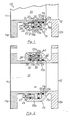
- FIG. 1 there is shown a breakaway pipe coupling 10 including two separable halves 11 and 12 respectively. Both halves 11, 12 have annular end flanges 11 a, 12a respectively for bolting to end flanges of pipes (not shown) which are to be coupled together by the coupling 10.
- Coupling half 12 has a sleeve 15 which has a first portion 15a which, receives the end portion 11 b of coupling half 11 and a second portion 15b which is radially spaced from the outside face of coupling half 11 to define an annular space 16.
- the end portion 11 b is of reduced diameter to define a shoulder 11 c against which an annular piston in the form of a ring 17 abuts.
- the ring 17 is prevented from axial movement relative to coupling half 11 by a circlip 18.
- a second annular piston in the form of ring 20 is received in the annular space 16 and is restrained from axial movement within sleeve portion 1 5b by virtue of a series of balls 22 (only one of which is shown) spaced circumferentially about the ring 20.
- Each ball 22 is received in a radially extending bore 23 and projects therefrom into an annular groove 21 , formed in sleeve portion 1 5b.
- Each ball 22 is prevented from moving radially inwards by virtue of a threaded stud 24 which is threadedly received in ring 20 and projects axially therefrom to extend through a peripheral flange 26 formed on coupling half 11.
- a nut 27 is received on each stud so that the coupling halves 11, 12 are secured to one another via each stud and ring 20.
- Each stud is provided with a waisted portion 24a which defines a frangible portion.
- Ring 20 and ring 17 are spaced from one another so as to define an annular fluid chamber 28 and radially extending bores 30 are provided circumferentially around coupling half 11 - for providing pressure communication between annular chamber 28 and fluid conduit 31.
- Bores 30 may be closed by a diaphragm 60, for instance as illustrated in Figure 5 so that chamber 28 is isolated from fluid flowing along conduit 31 in order to prevent debris carried by the fluid flowing along conduit 31 from settling out in chamber 28. Accordingly, chamber 28 may be filled with a fluid which is different to that flowing along conduit 31.
- the diaphragm 60 may therefore be of any suitable construction which enables fluid pressure to be transmitted between conduit 31 and chamber 28.
- the diaphragm shown in Figure 5 includes an annular ring 61 across which extends a relatively thin membrane 62.
- the ring 61 and membrane 62 may be made integrally from a suitable material such as a plastics material or a metal.
- Fluid pressure acting on opposed faces 20a and 17a of the pistons tends to urge the coupling halves together whilst fluid pressure acting within the conduit 31 tends to urge the coupling halves apart.
- the area of opposed faces 20a, 17a is chosen to be at least as large as the cross-sectional area of the conduit 31 so the resultant fluid force acting to axially move the coupling halves is substantially zero. However it will be appreciated that these areas may be varied so as to give a resultant force which either urges the coupling halves apart or urges them together.
- Ring 20 and ring 17 each provided with seals 36, 37 so as to prevent fluid leakage from annular chamber 28.
- a seal 38 is provided between end portion 11 b and sleeve portion 15a in order to prevent fluid leakage from conduit 31.
- Venting bores 40 are provided in sleeve portion 15b for venting the annular space 42. These vents prevent the creation of a vacuum on separation of the coupling halves and also prevent build up of fluid pressure in the event of failure of seal 38.
- the studs 24 are placed under stress.
- the frangible portion of the studs are designed to shear at a predetermined load and upon shearing each stud is axially withdrawn from ring 20 and ring 17 is moved into contact with ring 20. Due to the withdrawal of studs 24 the balls 22 are permitted to enter bores 23 and so leave groove 21 as the ring 17 urges ring 20 axially out of sleeve portion 15b.
- the coupling halves 11, 12 are completely separated.
- the balls 22 seated in individual recesses 22a and are held in position within the bores 23 by means of a plunger 50.
- Each fluid bore 30 is enlarged and positioned so that on breaking of frangible bolts 24 the bores 30 align with plungers 50 which are urged through bores 30 by each ball leaving its recess 22a.
- FIG. 3 and 4 shows a breakaway coupling 80 constructed as described above with reference to Figure 1 (and which may be modified in accordance with Figure 2) and additionally includes a valve means 81 which on separation of parts 11 and 12 automatically closes the conduit 31 in order to prevent excessive spillage of fluid from the conduit 31:
- the valve means 81 includes a plurality of petal elements 82 each of which is pivotally mounted in the coupling part 12 for movement between a fully retracted position as seen on the right hand side of Figure 3 to a fully extended position as shown on the left hand side of Figure 3.
- Each petal element 81 is provided with an actuation arm 82a which is acted upon by a pair of opposed pistons 84, 85 respectively which are housed in a bore formed in coupling part 12.
- piston 84 is biased by a spring 87 to move the actuation arm 82a to move its petal element toward its extended position.
- Piston 84 therefore provides the initial motive force for moving the petal element towards its fully extended position and thereafter the pressure of fluid within conduit 31 provides the motive force.
- the piston chamber 90 in which piston 85 moves is filled with a fluid which is permitted to escape from chamber 90 at a controlled rate on separation of the coupling parts. The pistons 85 thus control the rate at which petal elements 81 move to their fully extended positions.
- each petal element 81 it is presently preferred to have eight petal elements 81 and to control their rates of movement such that four alternate petal elements 81 reach their fully extended position rapidly as shown in Figure 4 so as to form a bridge against which the remaining petals may abut on reaching their fully extended position.
- the piston 85 for each petal element is arranged to act as a stop for movement of its associated petal.
- An internal sleeve 92 is provided which extends from the coupling part 11 and which axially withdraws from part 12 on separation of parts 11 and 12.
- the sleeve 92 is provided with aperture 98 for permitting fluid pressure communication between conduit 31 and the bores 30.
- Seals 94, 95 are provided between sleeve 92 and parts 11 and 12 so as to provide a sealed annular chamber 96 in which the valve means is housed.
- Chamber 96 is filled with a suitable fluid, such as a lubricating oil, to reduce the likelihood of the petal elements failing to move to their extended position after separation of parts 11 and 12.
Landscapes
- Engineering & Computer Science (AREA)
- General Engineering & Computer Science (AREA)
- Mechanical Engineering (AREA)
- Quick-Acting Or Multi-Walled Pipe Joints (AREA)
- Joints That Cut Off Fluids, And Hose Joints (AREA)
- Safety Valves (AREA)
Claims (9)
Applications Claiming Priority (2)
| Application Number | Priority Date | Filing Date | Title |
|---|---|---|---|
| GB8019613A GB2051993B (en) | 1979-06-16 | 1980-06-16 | Breakaway coupling |
| GB8019613 | 1980-06-16 |
Publications (2)
| Publication Number | Publication Date |
|---|---|
| EP0053110A1 EP0053110A1 (de) | 1982-06-09 |
| EP0053110B1 true EP0053110B1 (de) | 1984-07-25 |
Family
ID=10514066
Family Applications (1)
| Application Number | Title | Priority Date | Filing Date |
|---|---|---|---|
| EP81900213A Expired EP0053110B1 (de) | 1980-06-16 | 1981-01-17 | Trennkupplung |
Country Status (5)
| Country | Link |
|---|---|
| US (1) | US4501287A (de) |
| EP (1) | EP0053110B1 (de) |
| JP (1) | JPS57500944A (de) |
| DE (1) | DE3164928D1 (de) |
| WO (1) | WO1981003690A1 (de) |
Families Citing this family (12)
| Publication number | Priority date | Publication date | Assignee | Title |
|---|---|---|---|---|
| GB2121499A (en) * | 1982-06-02 | 1983-12-21 | Exxon Research Engineering Co | A pressure compensated breakaway pipe coupling |
| US4880257A (en) * | 1983-03-23 | 1989-11-14 | Max Bassett | Pressure compensation multi tubular safety joint |
| US4688827A (en) * | 1986-06-18 | 1987-08-25 | James Howden & Company Limited | Pipeline safety joint |
| US5141014A (en) * | 1991-05-28 | 1992-08-25 | M. Carder Industries, Inc. | Breakaway coupling |
| US6263988B1 (en) * | 1998-10-19 | 2001-07-24 | Jacob Matatof | Downhole drill system and de-coupling assembly |
| US6425443B1 (en) * | 2000-11-20 | 2002-07-30 | Schlumberger Technology Corporation | Pressure compensated disconnect system and method |
| NO323924B1 (no) * | 2004-08-31 | 2007-07-23 | Atle Kvamme | Anordning ved trykkompensert svivel |
| IT1402917B1 (it) * | 2010-12-06 | 2013-09-27 | Mib Italiana Spa | Dispositivo per la chiusura automatica di valvole di controllo in unità di collegamento separabili per tubi flessibili. |
| IT1402918B1 (it) * | 2010-12-06 | 2013-09-27 | Mib Italiana Spa | Valvola di controllo per unità di collegamento separabili per tubi flessibili. |
| ITMI20120693A1 (it) * | 2012-04-26 | 2013-10-27 | Mib Italiana Spa | Valvola di controllo con coppie di petali di diversa forma e dimensioni e con differenti velocita' di chiusura per unita' di collegamento separabili per tubi flessibili. |
| ITMI20120694A1 (it) * | 2012-04-26 | 2013-10-27 | Mib Italiana Spa | Valvola di controllo a petali con guarnizione di tenuta per unita' di collegamento separabili per tubi flessibili. |
| US10907759B2 (en) | 2019-04-12 | 2021-02-02 | Saudi Arabian Oil Company | Disconnectable fluid coupling |
Family Cites Families (8)
| Publication number | Priority date | Publication date | Assignee | Title |
|---|---|---|---|---|
| DE177719C (de) * | ||||
| US2406662A (en) * | 1944-09-14 | 1946-08-27 | Paul J Burchett | Valve mechanism |
| US3889985A (en) * | 1973-01-29 | 1975-06-17 | Swiss Corp Limited | Pressure compensated expansion joint |
| US3921656A (en) | 1974-06-20 | 1975-11-25 | Spectrum Ass Inc | Self-closing breakaway valve assemblies |
| US4071268A (en) | 1976-05-28 | 1978-01-31 | Pressure Science Incorporated | Pressure compensated slide joint |
| US4059288A (en) * | 1976-09-01 | 1977-11-22 | Hydrotech International, Inc. | Pressure balanced safety pipeline connector |
| DE2965416D1 (en) | 1978-02-04 | 1983-07-07 | Gall Thomson Maritime Ltd | Breakaway pipe coupling |
| GB2051993B (en) * | 1979-06-16 | 1983-04-27 | Gall Thomson Maritime Ltd | Breakaway coupling |
-
1981
- 1981-01-17 EP EP81900213A patent/EP0053110B1/de not_active Expired
- 1981-01-17 WO PCT/GB1981/000007 patent/WO1981003690A1/en not_active Ceased
- 1981-01-17 US US06/348,061 patent/US4501287A/en not_active Expired - Lifetime
- 1981-01-17 JP JP56500362A patent/JPS57500944A/ja active Pending
- 1981-01-17 DE DE8181900213T patent/DE3164928D1/de not_active Expired
Also Published As
| Publication number | Publication date |
|---|---|
| WO1981003690A1 (en) | 1981-12-24 |
| US4501287A (en) | 1985-02-26 |
| JPS57500944A (de) | 1982-05-27 |
| DE3164928D1 (en) | 1984-08-30 |
| EP0053110A1 (de) | 1982-06-09 |
Similar Documents
| Publication | Publication Date | Title |
|---|---|---|
| EP0053110B1 (de) | Trennkupplung | |
| US4724857A (en) | Pressure relief valve | |
| EP0159984B1 (de) | Trennkupplung für schlauchleitungen | |
| US3630214A (en) | Frangible coupling | |
| US4694859A (en) | Undersea hydraulic coupling and metal seal | |
| US3797510A (en) | Crashworthy valve | |
| US4809747A (en) | Quick disconnect device | |
| US4934652A (en) | Dual stage valve actuator | |
| US5538296A (en) | Swivel joint | |
| US5699822A (en) | Breakaway coupling device | |
| US5135264A (en) | Flow coupling with frangible pressure sensitive holding member to allow venting | |
| US5207243A (en) | Two-way piston check valve | |
| EP0006278B1 (de) | Abreissrohrkupplung | |
| EP0247275B1 (de) | Feuersicheres Absperrventil | |
| WO1986005231A1 (en) | Marine riser fill-up valve | |
| US5791366A (en) | Frangible quick disconnect coupling | |
| US4519411A (en) | Emergency disconnector for fluid loading and unloading lines | |
| GB2269216A (en) | Pressure balanced undersea hydraulic coupling with pressure-energised seals | |
| GB2051993A (en) | Breakaway coupling | |
| US4307744A (en) | Frangible intertank valve assembly | |
| US5577524A (en) | Large diameter resettable rupture pin relief valve | |
| US3530887A (en) | Quick disconnect coupling | |
| JPS62255691A (ja) | 多数のホ−ス接続を、手動で行うための差込結合装置 | |
| US11719373B2 (en) | Coupling with pressure relief | |
| US4821775A (en) | One shot valve |
Legal Events
| Date | Code | Title | Description |
|---|---|---|---|
| PUAI | Public reference made under article 153(3) epc to a published international application that has entered the european phase |
Free format text: ORIGINAL CODE: 0009012 |
|
| 17P | Request for examination filed |
Effective date: 19820202 |
|
| AK | Designated contracting states |
Designated state(s): DE FR NL |
|
| GRAA | (expected) grant |
Free format text: ORIGINAL CODE: 0009210 |
|
| AK | Designated contracting states |
Designated state(s): DE FR NL |
|
| REF | Corresponds to: |
Ref document number: 3164928 Country of ref document: DE Date of ref document: 19840830 |
|
| ET | Fr: translation filed | ||
| PLBE | No opposition filed within time limit |
Free format text: ORIGINAL CODE: 0009261 |
|
| STAA | Information on the status of an ep patent application or granted ep patent |
Free format text: STATUS: NO OPPOSITION FILED WITHIN TIME LIMIT |
|
| REG | Reference to a national code |
Ref country code: FR Ref legal event code: CD |
|
| 26N | No opposition filed | ||
| NLT1 | Nl: modifications of names registered in virtue of documents presented to the patent office pursuant to art. 16 a, paragraph 1 |
Owner name: PETROCON GALL THOMSON LIMITED TE LONDEN, GROOT-BRI |
|
| REG | Reference to a national code |
Ref country code: FR Ref legal event code: TP Ref country code: FR Ref legal event code: CD |
|
| NLS | Nl: assignments of ep-patents |
Owner name: GALL THOMSON LIMITED |
|
| NLT1 | Nl: modifications of names registered in virtue of documents presented to the patent office pursuant to art. 16 a, paragraph 1 |
Owner name: BEVERLEY INDUSTRIAL COUPLINGS LIMITED;GALL THOMSON |
|
| PGFP | Annual fee paid to national office [announced via postgrant information from national office to epo] |
Ref country code: DE Payment date: 20000117 Year of fee payment: 20 |
|
| PGFP | Annual fee paid to national office [announced via postgrant information from national office to epo] |
Ref country code: FR Payment date: 20000125 Year of fee payment: 20 |
|
| PGFP | Annual fee paid to national office [announced via postgrant information from national office to epo] |
Ref country code: NL Payment date: 20000131 Year of fee payment: 20 |
|
| PG25 | Lapsed in a contracting state [announced via postgrant information from national office to epo] |
Ref country code: NL Free format text: LAPSE BECAUSE OF EXPIRATION OF PROTECTION Effective date: 20010117 |
|
| NLV7 | Nl: ceased due to reaching the maximum lifetime of a patent |
Effective date: 20010117 |