EP0053429A2 - Système de direction assistée - Google Patents
Système de direction assistée Download PDFInfo
- Publication number
- EP0053429A2 EP0053429A2 EP81304586A EP81304586A EP0053429A2 EP 0053429 A2 EP0053429 A2 EP 0053429A2 EP 81304586 A EP81304586 A EP 81304586A EP 81304586 A EP81304586 A EP 81304586A EP 0053429 A2 EP0053429 A2 EP 0053429A2
- Authority
- EP
- European Patent Office
- Prior art keywords
- pump
- shaft
- steering
- tube
- disposed
- Prior art date
- Legal status (The legal status is an assumption and is not a legal conclusion. Google has not performed a legal analysis and makes no representation as to the accuracy of the status listed.)
- Withdrawn
Links
Images

Classifications
-
- B—PERFORMING OPERATIONS; TRANSPORTING
- B62—LAND VEHICLES FOR TRAVELLING OTHERWISE THAN ON RAILS
- B62D—MOTOR VEHICLES; TRAILERS
- B62D5/00—Power-assisted or power-driven steering
- B62D5/06—Power-assisted or power-driven steering fluid, i.e. using a pressurised fluid for most or all the force required for steering a vehicle
-
- B—PERFORMING OPERATIONS; TRANSPORTING
- B62—LAND VEHICLES FOR TRAVELLING OTHERWISE THAN ON RAILS
- B62D—MOTOR VEHICLES; TRAILERS
- B62D5/00—Power-assisted or power-driven steering
- B62D5/06—Power-assisted or power-driven steering fluid, i.e. using a pressurised fluid for most or all the force required for steering a vehicle
- B62D5/09—Power-assisted or power-driven steering fluid, i.e. using a pressurised fluid for most or all the force required for steering a vehicle characterised by means for actuating valves
- B62D5/093—Telemotor driven by steering wheel movement
- B62D5/097—Telemotor driven by steering wheel movement gerotor type
Definitions
- This invention relates to power steering systems.
- Power steering systems are used on many types of vehicles, including forklift trucks and other industrial vehicles, for providing assistance to the operator in maneuvering the vehicle.
- the most common types of power steering systems are hydraulic, having a hydraulic pump which is driven by a V-belt from the engine or the accessory power section in a vehicle powered by an internal combustion engine, or by a separate electric motor in an electrically powered vehicle.
- the pump functions continuously while the vehicle is being operated, thereby providing continuous hydraulic power to the steering system.
- the fluid circulates freely within the system; however, if a steering command is given by the operator, the circulating hydraulic fluid is directed to one or the other side of a double-acting hydraulic steer piston-and- cylinder mechanism which is mechanically linked to a pitman arm or other linkage in the steering mechanism of the vehicle, and controls the position of the steer wheels of the vehicle.
- the hydraulically operated power steering systems which are commonly used and have continuously operating hydraluic pumps, perform satisfactorily in providing power assisted steering; however, certain objectionable features are associated with these systems.
- the continuously operating hydraulic pump is energy wasteful, in that frequently no steering commands are given by the operator for relatively long periods of time, yet the pump operates continuously and circulates hydraluic fluid which is not required and serves no useful purpose at that time. The energy consumed in operating the pump is completely wasted when steering commands have not been given.
- a greater amount of fuel is consumed than if the pump operated only when steering commands were given and pressurized fluid was needed.
- the continuously operating hydraulic pump creates other undesirable effects.
- the energy loss from the electrical system to power the pump is dissipated in the form of heat, which can add to the discomfort of the operator, especially if the vehicle is being used in an already warm working environment.
- pumps and motors which are larger than the optimal size have been used, since the larger pumps and motors can operate at slower and less noisy speeds.
- the larger pumps and motors are not only less efficient, thus resulting in higher energy consumption than small pumps and motors, but the larger pumps and motors are also more costly to obtain and install, hence adding to the overall vehicle cost.
- the present invention enables many of the objectionable features inherent in the hydraulic power steering systems previously used to be overcome, principally by providing in a preferred embodiment means whereby the hydraulic pump of the power steering system is activated only when steering commands are given. Hence, if no steering commands are given, the pump does not operate, energy is not wasted and other undesirable effects such as heat and noise generation are substantailly reduced.
- the present invention provides a power steering system comprising a hydraulic pump characterized in that means is provided for relaying manual steering commands through one side of said pump and means is provided for relaying power assisted steering commands through the opposite side of said pump, said first mentioned means, said pump, and said second mentioned means being in coaxial alignment.
- steering input signals in the form of torque are translated to axial stress on a tube, the ends of which experience either axial compression or tension, depending upon the direction of steering input.
- Strain guages on the tube in a Wheatstone bridge connection detect the steering imput signals as to both direction and rate, and transmit the signals to a bi-directional amplifier for activation of a servo motor which operates the pump.
- a servo motor which operates the pump.
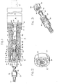
- numeral 10 designates a power steering system according to the present invention which may be used on any vehicle, but which is particularly advantageous when used on industrial-vehicles such as electric fork lift trucks and the like.
- Some of the particular advantages of the present system when used on electric industrial vehicles include increased efficiency, decreased noise generation, more efficient heat dissipation, extended service life, minimized space requirements and decreased initial system cost.
- Steering system 10 includes a bi-directional servo motor 12 connected to drive a hydraulic pump 14,through a reduction gear box 16.
- a steering imput sensing mechanism 18 is connected between a steering shaft assembly 20 and pump 14 for detecting the steering commands which occur when the steering wheel is turned by the vehicle operator and for transmitting the commands mechanically to the pump and electrically to the servo motor.
- the servo motor output is measured by a tachometer 21, and the measurements therefrom are used in correcting the servo motor output, if required.
- Pump 14 is a fixed displacement pump, preferably of the orbit type, having a rotor 22 operating in a stator 24.
- rotor 22 revolves about the centre line of stator 24 as it orbits in the stator.
- Rotor 22 has six lobes 26, and stator 24 has seven chambers 28 for receiving lobes 26; hence, for each orbit of the rotor within the stator, the rotor also revolves one-sixth of a turn about the centre line of the stator, but in the opposite direction to the direction of the orbit.
- the rotor must make six orbits within the stator to complete one full revolution about the centre line of the stator.
- a shaft 30 has male splines 32 and 43 on the ends thereof.
- Splines 32 engage with female splines 36 in rotor 22.
- a pump shaft 38 has a deep longitudinal bore 40 with female splines at the depth of the bore, and male splines 34 on shaft 30 engage with the splines at the depth of bore 40.
- Male splines 32 and 34 of shaft 30 are shaped to permit the shaft to wobble with respect to the female splines in the bore 40 of pump shaft 38 and female splines 36 of rotor 22.
- splines 34 at one end of shaft 30 wobble at the depth of bore 40 as the shaft rotates
- splines 32 at the opposite ends of shaft 30 wobble in rotor 22 as the rotor with shaft 30 connected thereto revolves and orbits within the stator.
- Pump shaft 38 has a series of grooves and recesses 48 in the outer surface thereof for transferring the hydraulic fluid between ports 50 and 52 in housing 42, one of which is the input port and the other of which is the output port, depending on the direction of operation of the bi-directional servo motor and the direction of fluid flow required for the steering command given.
- a bearing 54 is journaled in a bore of rotor 22 on the same centre line as the splines of the rotor, and an input shaft 56 from gear box 16 has an eccentric end 58 which mates with the inner race of bearing 54.
- shaft 56 causes eccentric end 58 to move in an orbital path, thereby orbiting rotor 22 within stator 24 about the centre line of the pump.
- One complete rotation of shaft 56 results in one orbit of rotor 22, thereby causing the rotor to move one-sixth of a full revolution in the opposite direction, as previously described.
- The'one-sixth of a revolution is transmitted to pump 38 by shaft 30 in the one to minus six ratio explained previously.
- Reduction gearbox 16 may be of any suitable type; however, the preferred arrangement is a planetary gear system with a reduction ratio of about six.
- the bi-directional servo motor 12 is a direct current electric motor, preferably of the permanent magnet type, having a moving coil type of armature optimized for low inertia which can accelerate from O to 1,000 rpm in about one millisecond. With the six to one mechanical advantage from gear box 16 and the six to one ratio of orbit pump 14, servo motor 12 has a 36 to 1 mechanical advantage in driving pump shaft 38.
- Steering shaft assembly 20 inlcudes a steering shaft 60 having a threaded end 62 to which a steering wheel, not shown, is attached.
- a shroud 64 encloses shaft 60 and has a flange 66 at the bottom thereof which mates with steering input sensing mechanism 18.
- the end of steering shaft 60 opposite from threaded end 62 has male splines 74 which mate with female splines in an intermediate shaft 76 for sensing mechanism 18.
- the intermediate shaft has a bore with female threads 78 which engage with a threaded end 80 of pump shaft 38.
- End plate 46 of pump 14 has an insert 82 with an outwardly extending externally threaded flange 84 which forms a threaded connection 86 with an internally threaded, thin walled metal tube 88.
- a housing 90 surrounds tube 88, and flange 92 extends outwardly from the end of the tube 88 and is disposed between flange 66 of shroud 64 and housing 90.
- Bolts 94 and 96 extend through flange 66 of shroud 64, flange 92 of tube 88, and housing 90, and are secured by threaded attachment into end plate 46 of pump 14.
- tube 88 is securely held within housing 90 by the threaded attachment to flange 84 at one end of the tube and by the securement of flange 92 between flange 66 and housing 90 at the other end of the tube. In this position, longitudinal movement of the tube as a whole is limited.
- Intermediate shaft 76 is supported within tube 88 by a roller bearing 102 which provides radial support and carries thrust loads from either direction parallel to the centre line of the steering system.
- Inner race 104 of bearing 102 is snugly fitted on shaft 76 and is supported in the direction of pump 14 against a shoulder 106 on the shaft.
- a nut 108 forms a threaded attachment 110 with shaft 76 and holds the bearing against shoulder 106.
- Outer race 112 of bearing 102 is snugly fitted within tube 88 and is held against an internal shoulder 114 of tube 88 by a retaining ring 116 which forms a threaded attachment 118 with the tube.
- Bearing 102 is fixed in this position between shaft 76 and tube 88 at the midpoint along the length of the tube.
- the manner in which steering shaft 60 is attached to intermediate shaft 76 and pump shaft 38, and the connection of one end of tube 88 to the pump housing end plate, and the other end of the tube between the sensing mechanism housing and steering shaft assembly, causes one end of the tube to undergo axial compression and the other end of the tube to undergo axial tension whenever a torque is applied to steering shaft 60 by turning of the steering wheel.
- the direction at which the torque is applied such as for a right or left hand turn, determines which end of the tube experiences compression and which experiences tension.
- Strain gauges 130,132, 134 and 136 are bonded to the external surface of tube 88 at suitable locations for sensing the axial stresses on the tube. Suitable strain gauges include uniaxial strain guages of either the wire or foil type; two element rosettes of a stacked foil, planar foil and shear planar foil type; three element rosettes of the 60° planar foil and 45 0 stacked wire type; or four element rosettes, all of which are well known to those familiar with the art.
- the electrical resistance of a wire such as the semiconductor strain gauges used in the steering system of the present invention, changes with changes in its length, and in the present steering system, as the tube undergoes axial tension or compression, the electrical resistances of the strain gauges change.
- the gauges are wired in a conventional Wheatstone bridge circuit to provide maximum output and inherent temperature compensation.
- FIG. 4 is a diagrammatical drawing of a suitable closed loop control system which may be used in the present steering mechanism.
- the left or l right hand input from the steering wheel is detected by the steering input sensing mechanism 18 and is transmitted to a bi-directional amplifier which relays a signal to operate servo motor 12.
- the motor output is measured by a tachometer 21 and is relayed back to the bi-directional amplifier by comparison against the desired motor output. Any. deviation from the desired result is amplified and used for correcting the error.
- Suitable dynamic braking and damping are incorporated in the system and they, as well as other features, such as torque limiting which may be either desirable or required, are well known in the servo motor control art.
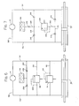
- FIGS 5, 6 and 7 are schematic diagrams of hydraulic circuits 140, 142 and 144 which may be used advantageously in the present steering system.
- pump 14 is connected to a steer device such as a double rod steer cylinder 150 by hydraulic lines 152 and 154 from ports 50 and 52 in the pump.
- Pilot operated check valves 156 and 158 are disposed in hydraulic lines 152 and 154, respectively, and have pilot lines 160 and 162 connected to the other of lines 152 and 154 than that in which the valve is disposed.
- Operating fluid for the hydraluic circuit is provided from reservoir 164 through a hydraulic line 166 having a lightly loaded check valve 168 and a shuttle valve 170 spring loaded as shown in the drawing with a pilot line 171 from hydraulic line 152.
- Hydraulic lines 172 and 174 from the shuttle valve provide a passage for the hydraulic fluid to or from one or the other side of the steer cylinder 150 at lines 152 and 154.
- a hydraulic line 176 forms a loop from shuttle valve 170 to hydraulic line 166 between reservoir 164 and check valve 168, and has an orifice 178 and a pressure relief valve 180 with a pilot line 182 disposed therein.
- a hydraulic line 184 having a lightly loaded check valve 186 is disposed between hydraulic line 176 and line 166 between check valve 168 and shuttle valve 170.
- valve 170 For example, if pump 14 is adjusted to pump hydraulic fluid through check valve 156 and line 152, the spool of shuttle valve 170 is sequenced to the right against its biasing spring, causing the piston of cylinder 150 to move to the right. Back pressure in the system operates through pilot line 162 to open check valve 158, thereby allowing fluid coming from cylinder 150 to pass through check valve 158 and pump 14. If the cylinder bottoms out and pump 14 continues to pump, fluid will pass through valve 170 and pilot line 182 to open release valve 180, thereby allowing fluid to pass through the release valve, hydraulic line 176, check valve 186, shuttle valve 170 and check valve 158 to pump 14.
- a feature of the hydraulic circuit 140 which makes the circuit particularly advantageous is that the circuit provides high temperature pressure relief. If both sides of the circuit become overpressurized due to elevated working temperatures, a small amount of fluid will pass through orifice 178 to reservoir 164. This occurs when the elevated pressure in line 152 causes the spool of shuttle valve 170 to sequence to the right against the biasing spring. Pressure in the right side of the circuit is then blocked from reaching orifice 178 and reservoir 164 by check valves 168 and 186; however, the greater pressure forces the piston of cylinder 150 slightly to the left, thereby displacing some fluid from the left side of the cylinder The fluid displaced from the left side of cylinder 150 passes from the left side of the circuit through pressure relief valve 180 to orifice 178 and into reservoir 164. Check valves 156 and 158 prevent normal load reactive forces, such as castering, from moving the piston of cylinder 150. If the check valves are removed from the circuit the system becomes load reactive, giving the driver feedback feel.
- hydraulic circuit 142 Similar numbers designate parts similar to those of the previously described circuit.
- Pump 14 pumps fluid through hydraulic lines 152 and 154 to move the piston of cylinder 150 either to the right or left.
- Hydraulic lines 190 and 192 are disposed between lines 152 and 154 and have disposed therein relief valves 194 and 196, respectively.
- Pilot lines 198 and 200 for relief valves 194 and 196 are connected such that an overpressure in line 154 causes relief valve 194 to open, permitting fluid to pass therethrough to line 152.
- An overpressure in line 152 causes relief valve 196 to open, thereby permitting the passage of fluid to line 154.
- a third hydraulic line 202 between lines 152 and 154 is connected to reservoir 164, and check valves 204 and 206 open to permit makeup fluid to pass into either side of the system.
- This particular circuit provides no pressure relief if both sides of the circuit are overpressurized as in the previous system. Load reactions, such as castering, cause cylinder 150 to move, thereby driving pump 14 and giving feedback and feel to the operator.
- the addition of check valves in lines 152 and 154, such as valves 156 and 158 in the previous circuit, causes the circuit to become nonreactive.
- FIG. 7 is a schematic view of yet another hydraulic circuit which may be used for the present steering system mechanism.
- hydraulic pump 14 is connected by hydraulic lines 152 and 154 to opposite sides of hydraulic steer cylinder 150. Fluid circulated by pump 14 will drive the piston of the cylinder to either the right or left as in the previous circuits.
- the steering system can be either load reactive or nonreactove, depending upon whether or not check valves are disposed in hydraulic lines 152 and 154.
- a hydraulic line 210 is disposed between lines 152 and 154 and contains check valves 212 and 214.
- a second hydraulic line 216 is disposed between hydraulic lines 152 and 154 and contains a pair of check valves 218 and 220 which, as can be seen in the drawing, permit fluid flow in the direction opposite from that of valves 212 and 214.
- a hydraulic line 222 is disposed between lines 210 and 216 and contains a relief valve 224 with a pilot line 226. Reservoir 164 communicates with the system through hydraulic line 228 having an orifice 230.
- the circuit of Fugure 7 also has pressure relief for overpressurization in both sides of the circuit which may result from expansion due to overheating, in that if both sides of the circuit become overpressurized, fluid will flow through check valves 212 and 214 into hydraulic line 222 and through relief valve 224 and orifice 230 into reservoir 164. If either side becomes underpressurized, makeup oil can enter the system through check valves 218 or 220.
- steering commands from the vehicle operator are initiated by turning of a steering wheel, not shown in the drawings, which rotates steering shaft 60 either to the right or left.
- the torque thus applied to steering shaft 60 is transmitted through the spline connection to intermediate shaft 76.
- the rigid axial mounting of tube 88 and the interconnection by bearing 102 between the tube and intermediate shaft 76 cause the portions of the tube on opposite sides of the bearing to undergo opposite types of axial stress.
- right hand torque applied to steering shaft 60 may cause the end of tube 88 to the right of bearing 102 in the drawing to undergo axial compression while at the same time the end of tube 88 to the left of the bearing undergoes axial tension.
- a left hand torque applied to steering shaft 60 may cause the right hand portion of tube 88 to undergo axial tension while the left hand portion of tube 88 undergoes axial compression.
- the type and degree of axial stress are detected by strain gauges 130, 132, 134 and 136, and the detection of stress is relayed to the bi-directional amplifier which activates bi-directional servo motor 12.
- the servo motor causes gear box output shaft 56 to rotate and eccentric end 58 thereof to move in an orbital path, thus causing rotor 22, which is connected to the eccentric end, to orbit in stator 24. If, as previously explained, a 6 to 1 mechanical advantage is obtained from gear box 16, and if pump 14 provides a further 6 to 1 mechanical advantage, servo motor 12 has a 36 to 1 mechanical advantage in driving pump shaft 38. If, for example, an additional 10 to 1 hydraulic advantage exists from shaft 38 to steer cylinder 150, the servo motor will have a 360 to 1 advantage with respect to steer angle generation. One full revolution of the armature in motor 12 will result in 1 degree of steer angle change. If full left steer to full right steer covers a range of about 180 0 in steer angle change, and is to be accomplished in approximately five seconds, the servo motor 12 will turn at about 180 turns per five seconds, or approximately 2,160 rpm.
- Tube 88 and bearing 102 are of sufficient strength and load bearing capacity to enable manual input steering commands to be transmitted to pump 14 to cause the pump to circulate fluid for manual steering. Threads 78 of shaft 76 are permitted to turn on to, or off of threaded end 80 by only a small amount; hence, the threaded connection permits manual operation of the pump. Thus, even if electrical power is lost, a vehicle having a present power steering system can still be controlled, and in the example just given, the operator will have a 10 to 1 advantage between the steering wheel and steer cylinder 150. All components of the present power steering system, beginning with the steering wheel and steering shaft 60 and extending through to tachometer 21, are arranged in coaxial alignment, thus providing a compact and space saving power steering arrangement.
- This arrangements of components wherein the servo motor and tachometer are at one end of the assembly, and a steering wheel, steering shaft assembly and steering input sensing mechanism are at the other end of the assembly, provides manual steering input to one end of pump 14 and powered servo motor imputs to the other end of the punp.
- the pump operates only in response to steering command inputs; thus, the servo motor, pump, and gear box will have extended life expectancies in that they will not operate continuously while the vehicle is running. Since, in normal operation, industrial vehicles and the like are guided through only moderate steer angle changes, the pump and motor will operate only occasionally and for short periods of time at reduced output. Thus, noise and heat generation are substantially reduced. Noise from the power steering system is detectable only when rapid and continuous wide angle steer changes are required, and the end to end coaxial alignment of components facilitates dissipation of the moderate amounts of heat which occur during operation of the present system.
- a strain gauge, brush and slip ring arrangement operating directly on shaft 76 could be utilized in steering input sensing mechanism 18, in which case tube 88 would be eliminated; however, such an arrangement of parts would be more complex and less durable than that disclosed previously.
- the disclosed arrangement, utilizing a shaft, bearing and tube with strain gauges wired in a Wheatstone bridge arrangement, is preferred in that the construction thereof is rugged and has few moving parts. Torque is mechanically converted to axial force, thus eliminating the need for slip rings and brushes, and the strain gauges may be hard wired to tube 88.
- the hydraulic circuitry disclosed provides means for creating either load reactive or load nonreactive steering systems, and one side over pressurization due to bottoming out of the steer cylinder and two side over pressurization due to expansion from heat or the like are automatically relieved. If under pressurization occurs, makeup oil is added from the reservoir.
Landscapes
- Engineering & Computer Science (AREA)
- Chemical & Material Sciences (AREA)
- Combustion & Propulsion (AREA)
- Transportation (AREA)
- Mechanical Engineering (AREA)
- Power Steering Mechanism (AREA)
- Steering Control In Accordance With Driving Conditions (AREA)
Applications Claiming Priority (2)
| Application Number | Priority Date | Filing Date | Title |
|---|---|---|---|
| US06/202,923 US4409789A (en) | 1980-11-03 | 1980-11-03 | Power steering system |
| US202923 | 1980-11-03 |
Publications (2)
| Publication Number | Publication Date |
|---|---|
| EP0053429A2 true EP0053429A2 (fr) | 1982-06-09 |
| EP0053429A3 EP0053429A3 (fr) | 1984-02-15 |
Family
ID=22751762
Family Applications (1)
| Application Number | Title | Priority Date | Filing Date |
|---|---|---|---|
| EP81304586A Withdrawn EP0053429A3 (fr) | 1980-11-03 | 1981-10-05 | Système de direction assistée |
Country Status (7)
| Country | Link |
|---|---|
| US (1) | US4409789A (fr) |
| EP (1) | EP0053429A3 (fr) |
| JP (1) | JPS5799471A (fr) |
| AU (1) | AU7702181A (fr) |
| BR (1) | BR8106896A (fr) |
| ES (1) | ES506790A0 (fr) |
| ZA (1) | ZA816529B (fr) |
Cited By (5)
| Publication number | Priority date | Publication date | Assignee | Title |
|---|---|---|---|---|
| GB2147256A (en) * | 1983-09-28 | 1985-05-09 | Trw Cam Gears Ltd | Power steering system |
| GB2159111A (en) * | 1984-05-25 | 1985-11-27 | Steering Developments Ltd | Driver assessment system |
| GB2181521A (en) * | 1985-10-11 | 1987-04-23 | Trw Cam Gears Ltd | Power assisted steering |
| WO1992012887A1 (fr) * | 1991-01-26 | 1992-08-06 | Alfred Teves Gmbh | Direction hydraulique assistee pour automobiles |
| EP0534332A1 (fr) * | 1991-09-26 | 1993-03-31 | Abb Truck Ab | Servomécanisme hydraulique, particulièrement pour le mécanisme de direction d'un véhicule |
Families Citing this family (15)
| Publication number | Priority date | Publication date | Assignee | Title |
|---|---|---|---|---|
| JPH0629037B2 (ja) * | 1984-11-13 | 1994-04-20 | カヤバ工業株式会社 | 全油圧式パワ−ステアリング装置 |
| BR9804945A (pt) * | 1997-05-28 | 2000-01-25 | K Tron Tech Inc | Sensor de força monolìtico. |
| US6923289B1 (en) | 2003-09-11 | 2005-08-02 | Sauer-Danfoss, Inc. | Closed circuit steering circuit for mobile vehicles |
| DE10345293A1 (de) * | 2003-09-30 | 2005-05-04 | Bayerische Motoren Werke Ag | Betriebsverfahren für ein hilfskraftverstärktes Hydro-Lenksystem eines Kraftfahrzeugs |
| US7661493B2 (en) | 2005-04-19 | 2010-02-16 | Nmhg Oregon, Llc | Power assisted steering for motorized pallet truck |
| US20070017733A1 (en) * | 2005-06-13 | 2007-01-25 | Edson Joey D | Vehicle power steering system |
| US7426977B2 (en) * | 2005-11-07 | 2008-09-23 | Fluid Routing Solutions, Inc. | Vehicle power steering system |
| US7487856B2 (en) * | 2006-08-30 | 2009-02-10 | Fluid Routing Solutions, Inc. | Electrically actuated, hydraulic power steering system |
| WO2014004829A1 (fr) * | 2012-06-28 | 2014-01-03 | Eaton Corporation | Ensemble d'entraînement pour un dispositif à pression de fluide rotatif |
| JP6323999B2 (ja) * | 2013-07-31 | 2018-05-16 | 株式会社タダノ | 作業用車両のステアリング装置 |
| TWI647143B (zh) * | 2017-12-28 | 2019-01-11 | 電動機車動力輪輪軸的散熱構造 | |
| CN108791481B (zh) * | 2018-05-29 | 2023-11-28 | 浙江万达汽车方向机有限公司 | 一种液压转向路感模拟器组件及模拟装置及方法 |
| DE102020106437B4 (de) | 2020-03-10 | 2024-09-26 | Danfoss Power Solutions Aps | Fluidsteuereinrichtung, insbesondere als Teil einer hydraulischen Lenkeinheit |
| DE102020106438B4 (de) | 2020-03-10 | 2022-03-31 | Danfoss Power Solutions Aps | Fluidsteuereinrichtung, insbesondere als Teil einer hydraulischen Lenkeinheit |
| DE102020106440B4 (de) * | 2020-03-10 | 2024-08-01 | Danfoss Power Solutions Aps | Hydraulische Lenkeinheit |
Family Cites Families (12)
| Publication number | Priority date | Publication date | Assignee | Title |
|---|---|---|---|---|
| USRE25291E (en) | 1956-06-08 | 1962-12-04 | Fluid pressure device and valve | |
| US2979148A (en) * | 1957-11-27 | 1961-04-11 | Gen Motors Corp | Vehicle steering system with oscillation damping |
| US2962108A (en) * | 1958-06-02 | 1960-11-29 | Gen Motors Corp | Servo system with controls for vehicular power steering |
| US3011579A (en) * | 1959-01-08 | 1961-12-05 | Gen Motors Corp | Steering system |
| US3173253A (en) * | 1963-01-23 | 1965-03-16 | Elias Jack | Flexible forward grain support |
| DE1947205A1 (de) * | 1969-09-18 | 1971-04-08 | Zahnradfabrik Friedrichshafen | Hydrostatische Lenkanlage,insbesondere fuer Kraftfahrzeuge |
| US3895888A (en) * | 1973-10-19 | 1975-07-22 | Trw Inc | Hydrostatic control unit |
| US4109679A (en) * | 1976-04-23 | 1978-08-29 | Eaton Corporation | Controller for fluid pressure operated devices |
| DE2917298C2 (de) * | 1979-04-28 | 1985-03-21 | Zahnradfabrik Friedrichshafen Ag, 7990 Friedrichshafen | Drehschiebereinrichtung zur Steuerung eines hydrostatischen Servoantriebs |
| DE2934618C2 (de) * | 1979-08-28 | 1983-06-30 | Danfoss A/S, 6430 Nordborg | Hydraulischer Momentverstärker für Lenkeinrichtungen von Kraftfahrzeugen |
| DE3006297A1 (de) * | 1980-02-20 | 1981-08-27 | Robert Bosch Gmbh, 7000 Stuttgart | Hydraulische lenkvorrichtung |
| DE3037206C2 (de) * | 1980-10-02 | 1986-06-05 | Danfoss A/S, Nordborg | Hydraulische Lenkeinrichtung für Fahrzeuge |
-
1980
- 1980-11-03 US US06/202,923 patent/US4409789A/en not_active Expired - Lifetime
-
1981
- 1981-09-21 ZA ZA816529A patent/ZA816529B/xx unknown
- 1981-10-05 EP EP81304586A patent/EP0053429A3/fr not_active Withdrawn
- 1981-10-26 BR BR8106896A patent/BR8106896A/pt unknown
- 1981-10-27 JP JP56170886A patent/JPS5799471A/ja active Pending
- 1981-11-02 ES ES506790A patent/ES506790A0/es active Granted
- 1981-11-02 AU AU77021/81A patent/AU7702181A/en not_active Abandoned
Cited By (7)
| Publication number | Priority date | Publication date | Assignee | Title |
|---|---|---|---|---|
| GB2147256A (en) * | 1983-09-28 | 1985-05-09 | Trw Cam Gears Ltd | Power steering system |
| FR2555538A1 (fr) * | 1983-09-28 | 1985-05-31 | Trw Cam Gears Ltd | Systeme de direction assistee pour vehicule, utilisant un fluide sous pression commande selectivement par deux soupapes a sens unique |
| GB2156752A (en) * | 1983-09-28 | 1985-10-16 | Trw Cam Gears Ltd | A power assistance steering system for a vehicle |
| GB2159111A (en) * | 1984-05-25 | 1985-11-27 | Steering Developments Ltd | Driver assessment system |
| GB2181521A (en) * | 1985-10-11 | 1987-04-23 | Trw Cam Gears Ltd | Power assisted steering |
| WO1992012887A1 (fr) * | 1991-01-26 | 1992-08-06 | Alfred Teves Gmbh | Direction hydraulique assistee pour automobiles |
| EP0534332A1 (fr) * | 1991-09-26 | 1993-03-31 | Abb Truck Ab | Servomécanisme hydraulique, particulièrement pour le mécanisme de direction d'un véhicule |
Also Published As
| Publication number | Publication date |
|---|---|
| BR8106896A (pt) | 1982-07-13 |
| AU7702181A (en) | 1982-05-13 |
| US4409789A (en) | 1983-10-18 |
| JPS5799471A (en) | 1982-06-21 |
| ES8206319A1 (es) | 1982-08-16 |
| ZA816529B (en) | 1982-09-29 |
| ES506790A0 (es) | 1982-08-16 |
| EP0053429A3 (fr) | 1984-02-15 |
Similar Documents
| Publication | Publication Date | Title |
|---|---|---|
| US4409789A (en) | Power steering system | |
| US12179857B2 (en) | Power steering mechanism for a vehicle | |
| US6575264B2 (en) | Precision electro-hydraulic actuator positioning system | |
| US4580651A (en) | Power assistance steering system for a vehicle | |
| US20080277187A1 (en) | Power steering apparatus | |
| EP0515052B1 (fr) | Système de direction assistée hydrostatique | |
| US3407894A (en) | Auxiliary means energizing fluid steering system upon deactivation of main pump | |
| US20040020708A1 (en) | Electric steering apparatus | |
| US4718514A (en) | Steering force control device for power steering apparatus | |
| US7337872B2 (en) | Hydraulic power assisted steering system | |
| US4940103A (en) | Power steering system for use in motor vehicle | |
| US7798282B2 (en) | Power assisted steering system | |
| US5186612A (en) | Variable pressure inlet system for hydraulic pumps | |
| US4274504A (en) | Power steering device | |
| JPH0645343B2 (ja) | 動力舵取装置の操舵力制御装置 | |
| US6790110B2 (en) | Marine power steering system | |
| JP7773554B2 (ja) | 車両、特に商用車用のステアリングシステム | |
| US5148885A (en) | Steerable utility vehicle | |
| EP0153805B1 (fr) | Système d'assistance de direction pour véhicule | |
| US5593002A (en) | Power steering system equipped with means for varying an assist torque thereof | |
| EP1167161B1 (fr) | Direction assistée hydraulique avec dispositif électrique de secours | |
| GB2154188A (en) | Power steering assembly | |
| US4414883A (en) | Power-assisted steering device | |
| US2984186A (en) | Multiple pump unit | |
| JPH06503B2 (ja) | 電動式パワ−ステアリング装置 |
Legal Events
| Date | Code | Title | Description |
|---|---|---|---|
| PUAI | Public reference made under article 153(3) epc to a published international application that has entered the european phase |
Free format text: ORIGINAL CODE: 0009012 |
|
| AK | Designated contracting states |
Designated state(s): DE FR GB |
|
| 17P | Request for examination filed |
Effective date: 19820519 |
|
| PUAL | Search report despatched |
Free format text: ORIGINAL CODE: 0009013 |
|
| AK | Designated contracting states |
Designated state(s): DE FR GB |
|
| STAA | Information on the status of an ep patent application or granted ep patent |
Free format text: STATUS: THE APPLICATION HAS BEEN WITHDRAWN |
|
| 18W | Application withdrawn |
Withdrawal date: 19840327 |
|
| 18W | Application withdrawn |
Withdrawal date: 19840327 |
|
| RIN1 | Information on inventor provided before grant (corrected) |
Inventor name: CHICHESTER, WILLARD LYLE Inventor name: HANSEN, HOWARD CLAIR |