EP0053515A1 - Arbre de rotor - Google Patents
Arbre de rotor Download PDFInfo
- Publication number
- EP0053515A1 EP0053515A1 EP81305662A EP81305662A EP0053515A1 EP 0053515 A1 EP0053515 A1 EP 0053515A1 EP 81305662 A EP81305662 A EP 81305662A EP 81305662 A EP81305662 A EP 81305662A EP 0053515 A1 EP0053515 A1 EP 0053515A1
- Authority
- EP
- European Patent Office
- Prior art keywords
- rotor shaft
- sleeve
- segments
- alloy steel
- journal portion
- Prior art date
- Legal status (The legal status is an assumption and is not a legal conclusion. Google has not performed a legal analysis and makes no representation as to the accuracy of the status listed.)
- Granted
Links
- 229910000831 Steel Inorganic materials 0.000 claims abstract description 33
- 239000010959 steel Substances 0.000 claims abstract description 33
- 238000003466 welding Methods 0.000 claims abstract description 32
- 229910052804 chromium Inorganic materials 0.000 claims abstract description 20
- 229910000851 Alloy steel Inorganic materials 0.000 claims abstract description 16
- 229910000599 Cr alloy Inorganic materials 0.000 claims abstract description 14
- 229910000734 martensite Inorganic materials 0.000 claims abstract description 6
- 229910001563 bainite Inorganic materials 0.000 claims abstract description 5
- 239000000463 material Substances 0.000 claims description 11
- 230000008878 coupling Effects 0.000 claims description 10
- 238000010168 coupling process Methods 0.000 claims description 10
- 238000005859 coupling reaction Methods 0.000 claims description 10
- 230000002093 peripheral effect Effects 0.000 claims description 8
- 229910052750 molybdenum Inorganic materials 0.000 claims description 7
- 229910052720 vanadium Inorganic materials 0.000 claims description 6
- 229910052748 manganese Inorganic materials 0.000 claims description 2
- 230000013011 mating Effects 0.000 claims description 2
- 229910052759 nickel Inorganic materials 0.000 claims description 2
- 229910052758 niobium Inorganic materials 0.000 claims description 2
- 239000002184 metal Substances 0.000 description 15
- 229910052751 metal Inorganic materials 0.000 description 15
- 230000007547 defect Effects 0.000 description 4
- 238000005461 lubrication Methods 0.000 description 4
- 238000010276 construction Methods 0.000 description 3
- 238000000034 method Methods 0.000 description 3
- 229910000897 Babbitt (metal) Inorganic materials 0.000 description 2
- 239000010953 base metal Substances 0.000 description 2
- 239000011324 bead Substances 0.000 description 2
- 238000005336 cracking Methods 0.000 description 2
- 238000001514 detection method Methods 0.000 description 2
- 238000010894 electron beam technology Methods 0.000 description 2
- 230000035515 penetration Effects 0.000 description 2
- 238000005452 bending Methods 0.000 description 1
- 230000015572 biosynthetic process Effects 0.000 description 1
- 239000012141 concentrate Substances 0.000 description 1
- 239000000470 constituent Substances 0.000 description 1
- 230000007797 corrosion Effects 0.000 description 1
- 238000005260 corrosion Methods 0.000 description 1
- 230000001747 exhibiting effect Effects 0.000 description 1
- 239000010419 fine particle Substances 0.000 description 1
- 238000004519 manufacturing process Methods 0.000 description 1
- 239000007769 metal material Substances 0.000 description 1
- 239000000203 mixture Substances 0.000 description 1
- 230000003647 oxidation Effects 0.000 description 1
- 238000007254 oxidation reaction Methods 0.000 description 1
- 230000001590 oxidative effect Effects 0.000 description 1
- 239000002245 particle Substances 0.000 description 1
- 235000019592 roughness Nutrition 0.000 description 1
- 238000003892 spreading Methods 0.000 description 1
- 239000000126 substance Substances 0.000 description 1
- 230000003746 surface roughness Effects 0.000 description 1
Images
Classifications
-
- F—MECHANICAL ENGINEERING; LIGHTING; HEATING; WEAPONS; BLASTING
- F16—ENGINEERING ELEMENTS AND UNITS; GENERAL MEASURES FOR PRODUCING AND MAINTAINING EFFECTIVE FUNCTIONING OF MACHINES OR INSTALLATIONS; THERMAL INSULATION IN GENERAL
- F16C—SHAFTS; FLEXIBLE SHAFTS; ELEMENTS OR CRANKSHAFT MECHANISMS; ROTARY BODIES OTHER THAN GEARING ELEMENTS; BEARINGS
- F16C3/00—Shafts; Axles; Cranks; Eccentrics
- F16C3/02—Shafts; Axles
-
- F—MECHANICAL ENGINEERING; LIGHTING; HEATING; WEAPONS; BLASTING
- F01—MACHINES OR ENGINES IN GENERAL; ENGINE PLANTS IN GENERAL; STEAM ENGINES
- F01D—NON-POSITIVE DISPLACEMENT MACHINES OR ENGINES, e.g. STEAM TURBINES
- F01D25/00—Component parts, details, or accessories, not provided for in, or of interest apart from, other groups
- F01D25/16—Arrangement of bearings; Supporting or mounting bearings in casings
-
- F—MECHANICAL ENGINEERING; LIGHTING; HEATING; WEAPONS; BLASTING
- F16—ENGINEERING ELEMENTS AND UNITS; GENERAL MEASURES FOR PRODUCING AND MAINTAINING EFFECTIVE FUNCTIONING OF MACHINES OR INSTALLATIONS; THERMAL INSULATION IN GENERAL
- F16D—COUPLINGS FOR TRANSMITTING ROTATION; CLUTCHES; BRAKES
- F16D1/00—Couplings for rigidly connecting two coaxial shafts or other movable machine elements
- F16D1/06—Couplings for rigidly connecting two coaxial shafts or other movable machine elements for attachment of a member on a shaft or on a shaft-end
- F16D1/064—Couplings for rigidly connecting two coaxial shafts or other movable machine elements for attachment of a member on a shaft or on a shaft-end non-disconnectable
- F16D1/068—Couplings for rigidly connecting two coaxial shafts or other movable machine elements for attachment of a member on a shaft or on a shaft-end non-disconnectable involving gluing, welding or the like
-
- F—MECHANICAL ENGINEERING; LIGHTING; HEATING; WEAPONS; BLASTING
- F16—ENGINEERING ELEMENTS AND UNITS; GENERAL MEASURES FOR PRODUCING AND MAINTAINING EFFECTIVE FUNCTIONING OF MACHINES OR INSTALLATIONS; THERMAL INSULATION IN GENERAL
- F16C—SHAFTS; FLEXIBLE SHAFTS; ELEMENTS OR CRANKSHAFT MECHANISMS; ROTARY BODIES OTHER THAN GEARING ELEMENTS; BEARINGS
- F16C2226/00—Joining parts; Fastening; Assembling or mounting parts
- F16C2226/30—Material joints
- F16C2226/36—Material joints by welding
Definitions
- the present invention relates to a rotor shaft and, more particularly, to a rotor shaft made of a steel containing 8 to 13% of Cr suitable for use as a rotor shaft of steam turbine.
- 12% Cr alloy steel is finding a spreading use as the material of rotor shafts of steam turbines, because of its high mechanical strength and toughness at high temperature range.
- the 12% Cr alloy steel however, has inferior bearing properties, particularly wear resistance property.
- various accidents are often experienced such as seizure of the bearing metal in support of the rotor journal, damaging of the rotor journals and bearings and so forth, due to jamming of foreign matters such as dusts in the bearing.
- Japanese Patent Laid- open Publication No. 16744/80 discloses a rotor shaft made of a 12% Cr alloy steel and having journal portions covered by a layer of a metal having good bearing properties formed by metallizing, as well as a rotor shaft made of a 12% Cr alloy steel and having journal portions build-up welded with a welding rod of a metal having good bearing properties.
- the rotor shaft having the journal portions covered with the metal layer formed by metallizing exhibits only a small affinity or bonding force between the metal layer and the base metal of the rotor.
- the metal layer formed by the metallizing tends to involve oxides and voids which seriously lower the tensile strength and toughness of the metal layer. In consequence, the metal layer formed by the metallizing is liable to be separated from the journal portion when a bending force is applied to the rotor shaft.
- the rotor shaft having journal portions build-up welded with a welding rod having good bearing properties also involves the following problem. Namely, in order to prevent the cracking in the build-up welded layer, it is necessary to strictly select the kind of the build-up welding metal in relation to the welding condition relating to the base metal. This sometimes imposes a difficulty in the selection of the build-up welding metal having good bearing properties. In other words, in some cases, the padding metal is selected to meet the welding condition, at the cost of a poor bearing characteristics.
- an object of the invention is to provide a rotor shaft having superior bearing properties, made of a Cr alloy steel having a high Cr content.
- Another object of the invention is to provide a rotor shaft made of a Cr alloy steel, provided with a sleeve having superior bearing properties, the sleeve being attachable to a journal portion of the rotor shaft even when the rotor shaft has a coupling integral therewith.
- the invention provides
- rotor made of 12% Cr steel or "12% Cr steel rotor” is used to mean a steam turbine rotor made of a Cr alloy steel having martensite structure and containing 8-13% Cr.
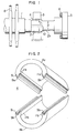
- a rotor 1 made of 12% Cr steel has a multiplicity of stages of moving blades disposed in the axial direction of the rotor, each stage including a large number of radially arranged moving blades 8.
- the rotor 1 is adapted to be connected to a rotor (not shown) of a generator through a coupling 5 which is formed on one end of the rotor 1 integrally therewith.
- Coupling bolts 6 are attached to the coupling 6.
- the rotor 1 made of 12% Cr steel is adapted to be rotatably supported by bearings 3.
- the portion of the rotor 1 facing each bearing 3 constitutes a journal portion 2 around which fitted is a cylindrical sleeve 4 which is divided in circumferential direction into two segments.
- the portion 2b of the rotor between the journal portion 2 and the coupling 5 has a diameter d which is several millimeters smaller than the outside diameter D of the journal portion 2.
- the assembling and/or welding of two segments 4a, 4b of the sleeve 4 is made on this rotor portion 2b of reduced diameter to facilitate the formation of the cylindrical sleeve 4.
- the cylindrical sleeve 4 thus formed is then fitted around the journal portion 2 of the rotor.
- the sleeve 4 consists of two circumferential segments 4a, 4b which are provided at their joint surfaces with mating projection 9a, and recess 9b which in combination constitute fitting portions 9.
- Each projection 9a and each recess 9b have dove-tail configurations in order to hold two segments in one body withstanding the centrifugal force acting on the sleeve 4 during the rotation of the rotor.
- axial guide grooves 10 are formed in the diametrically opposing portions of the peripheral surface of the journal portion 2.
- the side surfaces of the projections 9a and the side surfaces of the wall defining the recesses 9b, constituting the diametrically opposing portions of the inner peripheral surface of the sleeve 4 are protruded inwardly as at lla, llb.
- protrusions lla, Ilb of the sleeve segments 4a, 4b are adapted to be fitted into the aforementioned grooves 10 in the rotor surface, so that a part of the load applied to the sleeve 4 by the centrifugal force is shared by the fitting of the protrusions lla, llb into the groove 10 as shown in Fig. 3.
- the sleeve 4 is mounted on the journal portion 2 of the rotor in accordance with the following procedure. That is, after securing the sleeve 4 around the journal portion 2, the fitting portion 9 is caulked by rolls, etc. pressed against the outer peripheral surface of the sleeve to eliminate any play in the fitting portion 9. Then, the outer peripheral surface of the sleeve 4 is mechanically processed into circular form.
- the sleeve 4 is made of a metal having superior bearing properties.
- This metal is preferably a low alloy steel such as a bainite steel consisting essentially of 0.2 to 2.25% Cr, 0.2 to 1% Mo, and the balance Fe. More preferably, the material of the sleeve 4 is a bainite steel which contains, in addition to the constituents mentioned above, 0.05 to 0.5% V.
- a low alloy steel is preferably used as the material of the sleeve 4 as follows. Namely, the low alloy steel has a heat conductivity which is about 30% higher than that of the 12% Cr steel used as the material of the rotor, so that the sleeve 4 exhibits a small temperature rise during the rotation of the rotor. In consequence, the tendency of seizure between the sleeve 4 and the bearing 3 due to the temperature rise caused by friction is suppressed advantageously.
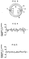
- the experiment was conducted using a rotor made of the 12% Cr steel and a rotor of the same material as the sleeve, i.e. a low alloy steel containing Cr, Mo and V. These rotors were rotatably supported at their journal portions by bearings and rotated at a predetermined speed, while supplying a lubrication oil to the bearings. Fine particles of foreign matters were added to the lubrication oil, and the extent of damage of the journal portions due to the presence of the foreign matters was examined.
- Figs. 4 and 5 show the roughnesses of the journal surfaces of the rotors made of the 12% Cr steel and the low alloy steel containing Cr, Mo and V, respectively, as observed after lapse of a predetermined time from the commencement of addition of foreign matter particles to the lubrication oil. From these Figures, it will be seen that the low alloy steel exhibits superior wear resistance to the 12% Cr.steel.
- the 12% Cr steel used as the material of the rotor shaft is preferably a forged steel having all martensite structure and consisting essentially of 0.1 to 0.3% Co, less than 0.6% Si, 0.4 to 1.5% Mn, less than 1.2% Ni, 10 to 14% Cr, 0.5 to 1.5% Mo, 0.05 to 0.3% V, 0.02 to 0.15% Nb, 0.04 to 0.1% of N, and the balance Fe.
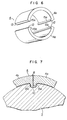
- this embodiment has a cylindrical sleeve 4 made of a low alloy steel and divided in the circumferential direction into segments 4a, 4b as shown in Fig. 6.
- the number of segments is not limited to two and it is possible to divide the sleeve into two or more segments.
- Each abutting surface 12 constituting the joint surface between adjacent sleeves 4a, 4b is provided with a bevel for welding.
- a projection 15a or 15b is formed on the joint surface 12 to project radially inwardly therefrom.
- the sleeve segments 4a, 4b have been precisely processed taking into account the tolerance for shrinkage fit. These segments 4a, 4b are assembled together on the reduced-diameter portion 2b of the rotor and jointed to each other by welding. The sleeve 4 thus formed is then fitted around the journal portion. In consequence, the sleeve 4 is fitted around the journal at a tightness equivalent to that achieved by a shrinkage.fit.
- the welding conducted on the joint surfaces 12 of the sleeve segments 4a, 4b may be conducted by arc welding, electron beam welding or any other known welding technic.
- the sleeve 4 is subjected, after the welding, to an SR treatment for reducing the residual stress in the weld zone and for improving the toughness.
- the SR treatment is preferably conducted in vacuum or in a non-oxidizing atmosphere. After the SR treatment of the sleeve 4, the surface is finished and then the sleeve 4 is fitted by a shrinkage fit.
- the SR treatment is preferably conducted at 650 to 700°C and for 0.5 to 5 hours.
- the sleeve segments 4a, 4b themselves have constructions as shown in Fig. 6. These segments were brought together on the reduced-diameter portion 2b of the rotor, and welding was conducted on the bevels of the joint surfaces 12 between the sleeve segments 4a, 4b to unite these sleeve segments. More specifically, the welding was carried out by preheating the joint surfaces up to 250 to 300 0 C and maintaining the same temperature between successive passes. The first pass was made by TIG welding to obtain a sufficient penetration to the back side of the bevel.
- the subsequent passes were made by means of a covered arc welding rod for low alloy steel.
- the sleeve 4 was held at a predetermined temperature and fitted around the journal portion 2 of the rotor. More specifically, the sleeve 4, the temperature of which is 250 to 300°C after the welding, was directly fitted around the journal portion. Then, an ultrasonic flaw detection and a magnetic flaw detection were conducted to check the weld part for any flaw or defect in the weld part, but no flaw nor defect was found. Then, the outer surface of the sleeve was mirror-finished and the sleeve was subjected to a running test in combination with a bearing made of Babbitt metal. No seizure of the journal was observed and superior bearing characteristics were confirmed.
- Fig. 7 is a sectional view of the journal portion 2 of a rotor 1 having the welded sleeve 4 fitted around the journal portion
- the projections 15a, 15b on the back side of the bevels of joint surfaces 12 of the sleeve segments are adapted to be received by grooves 10 formed in the journal surface as in the case of embodiment shown in Fig. 1.
- the sleeve segments 4a, 4b are welded to each other by means of a beam of a high energy density.
- the weld 8 shown in Fig. 7 is formed by an electron beam welding.
- the sleeve 4 thus formed can be used as it is, without necessitating troublesome work for eliminating any weld defect which tends to appear in the weld part of the sleeve due to insufficient penetration.
- the projections 15a, 15b are effective also in preventing the weld bead from reaching the rotor surface.
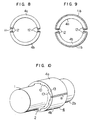
- Figs. 8 and 9 show different embodiments in which the abutting surfaces constituting the bevels of the sleeve segments, as well as the entire surfaces of the sleeve segments, are beforehand coated with metal layers lla, llb formed by build-up welding. More specifically, in the embodiment shown in Fig. 8, the build-up welding is effected only on the joint surfaces 12 to form the layer lla. By so doing, it is possible to omit the SR treatment which has to be made after the welding of the sleeve segments. In the embodiment shown in Fig. 9, the entire surfaces of the sleeve segments 4a, 4b including the joint surfaces 12 are covered by the metal layer llb formed by build-up welding.
- the whole part of the outer surface of the sleeve 4 is formed of the metal layer formed by build-up welding, so that it is possible to obtain uniform wear properties over the whole surface of the sleeve 4.
- The.material used for the build-up welding preferably has a chemical composition same as that of the material of the sleeve. It is also preferred to impart a peening, after the welding for jointing two sleeve segments, to the weld part to reduce the level of the residual stress in the weld zone.
- Fig. 10 shows a different embodiment in which a multiplicity of longitudinal guide grooves 10 are formed in the surface of the journal portion 2 at a predetermined pitch in the circumferential direction.
- the sleeve 4 in the assembled state has a multiplicity of inward protrusions 13 adapted to be received by corresponding grooves 10. If a slight gap is formed in the fitting portion between the groove 10 and the associated protrusion 13 of the sleeve, the lubrication oil may come into the gap to corrode the journal during the operation of the rotor.
- the outer peripheral surface of the sleeve 4 is caulked by rolls after fitting of the sleeve 4 around the journal portion 2 and, then, the outer peripheral surface of the sleeve 4 is mechanically processed into a circular form.
- these segments are brought into abutment with each other at the joint surfaces and welding is effected on these joint surfaces thereby to integrate these segments through the weld zones 8.
Landscapes
- Engineering & Computer Science (AREA)
- General Engineering & Computer Science (AREA)
- Mechanical Engineering (AREA)
- Ocean & Marine Engineering (AREA)
- Turbine Rotor Nozzle Sealing (AREA)
Applications Claiming Priority (4)
| Application Number | Priority Date | Filing Date | Title |
|---|---|---|---|
| JP17059780A JPS5793603A (en) | 1980-12-02 | 1980-12-02 | Rotor for steam turbine and method of manufacturing said rotor |
| JP170597/80 | 1980-12-02 | ||
| JP17059580A JPS5794118A (en) | 1980-12-02 | 1980-12-02 | Rotor shaft |
| JP170595/80 | 1980-12-02 |
Publications (2)
| Publication Number | Publication Date |
|---|---|
| EP0053515A1 true EP0053515A1 (fr) | 1982-06-09 |
| EP0053515B1 EP0053515B1 (fr) | 1985-08-07 |
Family
ID=26493545
Family Applications (1)
| Application Number | Title | Priority Date | Filing Date |
|---|---|---|---|
| EP81305662A Expired EP0053515B1 (fr) | 1980-12-02 | 1981-12-01 | Arbre de rotor |
Country Status (3)
| Country | Link |
|---|---|
| US (1) | US4426162A (fr) |
| EP (1) | EP0053515B1 (fr) |
| DE (1) | DE3171734D1 (fr) |
Cited By (3)
| Publication number | Priority date | Publication date | Assignee | Title |
|---|---|---|---|---|
| EP0068496A1 (fr) * | 1981-07-01 | 1983-01-05 | Hitachi, Ltd. | Arbre de rotor en acier allié au chrome |
| FR2910092A1 (fr) * | 2006-12-14 | 2008-06-20 | Renault Sas | Arbre de palier hydrodynamique |
| FR2999967A1 (fr) * | 2012-12-20 | 2014-06-27 | Alstom Hydro France | Procede de fixation de deux pieces metalliques entre elles |
Families Citing this family (12)
| Publication number | Priority date | Publication date | Assignee | Title |
|---|---|---|---|---|
| JPS58138209A (ja) * | 1982-02-08 | 1983-08-17 | Hitachi Ltd | 蒸気タ−ビン用ロ−タシヤフト |
| JPS58178804A (ja) * | 1982-04-14 | 1983-10-19 | Hitachi Ltd | 蒸気タ−ビンロ−タシヤフト |
| US4688688A (en) * | 1982-06-04 | 1987-08-25 | Handling Systems, Inc. | Jib crane arrangement having a rotatable mast |
| US4653344A (en) * | 1985-01-24 | 1987-03-31 | Belco Industries Incorporation | Laterally-disengageable bearing system |
| DE3802275A1 (de) * | 1988-01-27 | 1989-08-10 | Mtu Friedrichshafen Gmbh | Geteiltes gleitlager |
| US5072821A (en) * | 1990-12-07 | 1991-12-17 | Otis Elevator Company | Escalator/people mover bearing |
| ES2228034T3 (es) * | 1998-04-23 | 2005-04-01 | Nhk Spring Co. Ltd. | Dispositivo de retencion para un elemento de vastago. |
| US6802457B1 (en) | 1998-09-21 | 2004-10-12 | Caterpillar Inc | Coatings for use in fuel system components |
| US6715693B1 (en) * | 2000-02-15 | 2004-04-06 | Caterpillar Inc | Thin film coating for fuel injector components |
| US6796377B2 (en) * | 2002-07-23 | 2004-09-28 | Halliburton Energy Services, Inc. | Anti-rotation apparatus for limiting rotation of cementing plugs |
| GB201700995D0 (en) * | 2017-01-20 | 2017-03-08 | Edwards Ltd | Multi-stage vacuum booster pump rotor |
| US11859336B2 (en) * | 2021-11-29 | 2024-01-02 | Whirlpool Corporation | Laundry machine and spin tube for laundry machine |
Citations (3)
| Publication number | Priority date | Publication date | Assignee | Title |
|---|---|---|---|---|
| FR673254A (fr) * | 1929-04-11 | 1930-01-13 | Procédé pour revêtir les pièces mécaniques cylindriques, mâles ou femelles, avec une matière dure résistant à lusure | |
| US2242996A (en) * | 1939-07-24 | 1941-05-20 | Andrews Henry George | Replaceable bearing |
| US2481931A (en) * | 1947-02-06 | 1949-09-13 | Kester William Frank | Replaceable bearing journal assembly |
Family Cites Families (4)
| Publication number | Priority date | Publication date | Assignee | Title |
|---|---|---|---|---|
| US121318A (en) | 1871-11-28 | Improvement in metallic columns | ||
| US2704234A (en) | 1952-12-19 | 1955-03-15 | Glacier Co Ltd | Plain bearings |
| US2913290A (en) | 1957-08-28 | 1959-11-17 | Gen Motors Corp | Journal shaft bearing |
| US3022126A (en) | 1959-04-01 | 1962-02-20 | Preston G Siebert | Bearing and shround combination |
-
1981
- 1981-12-01 US US06/326,351 patent/US4426162A/en not_active Expired - Fee Related
- 1981-12-01 EP EP81305662A patent/EP0053515B1/fr not_active Expired
- 1981-12-01 DE DE8181305662T patent/DE3171734D1/de not_active Expired
Patent Citations (3)
| Publication number | Priority date | Publication date | Assignee | Title |
|---|---|---|---|---|
| FR673254A (fr) * | 1929-04-11 | 1930-01-13 | Procédé pour revêtir les pièces mécaniques cylindriques, mâles ou femelles, avec une matière dure résistant à lusure | |
| US2242996A (en) * | 1939-07-24 | 1941-05-20 | Andrews Henry George | Replaceable bearing |
| US2481931A (en) * | 1947-02-06 | 1949-09-13 | Kester William Frank | Replaceable bearing journal assembly |
Cited By (3)
| Publication number | Priority date | Publication date | Assignee | Title |
|---|---|---|---|---|
| EP0068496A1 (fr) * | 1981-07-01 | 1983-01-05 | Hitachi, Ltd. | Arbre de rotor en acier allié au chrome |
| FR2910092A1 (fr) * | 2006-12-14 | 2008-06-20 | Renault Sas | Arbre de palier hydrodynamique |
| FR2999967A1 (fr) * | 2012-12-20 | 2014-06-27 | Alstom Hydro France | Procede de fixation de deux pieces metalliques entre elles |
Also Published As
| Publication number | Publication date |
|---|---|
| US4426162A (en) | 1984-01-17 |
| EP0053515B1 (fr) | 1985-08-07 |
| DE3171734D1 (en) | 1985-09-12 |
Similar Documents
| Publication | Publication Date | Title |
|---|---|---|
| US4426162A (en) | Rotor shaft | |
| US5160243A (en) | Turbine blade wear protection system with multilayer shim | |
| US5240375A (en) | Wear protection system for turbine engine rotor and blade | |
| US4962586A (en) | Method of making a high temperature - low temperature rotor for turbines | |
| KR920010894B1 (ko) | 스티일 샤프트 복합 알루미늄 합금 로우터 | |
| EP0179539B1 (fr) | Rotor de turbine et sa méthode de fabrication | |
| US4566810A (en) | Steam turbine rotor shaft | |
| US11761429B2 (en) | Slide bearing, in particular for a gearbox of a wind turbine | |
| US4497670A (en) | Rotor shaft and manufacturing method thereof | |
| JP6110741B2 (ja) | 摺動部材付きのユニソンリング及び摺動部材付きのユニソンリングの製造方法 | |
| WO2011061253A1 (fr) | Joint à labyrinthe et procédé de production d'un joint à labyrinthe | |
| JPH0653307B2 (ja) | 円柱状部材の溶接修理方法 | |
| Wulpi | Failures of shafts | |
| WO2006056394A2 (fr) | Turbocompresseur a gaz d'echappement pour moteur a combustion interne | |
| JP2003221838A (ja) | 作業機連結装置 | |
| EP0068496B1 (fr) | Arbre de rotor en acier allié au chrome | |
| DE4307561A1 (de) | Lagerung einer Welle in einem Maschinengehäuse, insbesondere Kurbelwelle im Triebwerksgehäuse einer Brennkraftmaschine | |
| Miller et al. | Failures of Shafts | |
| US10520012B1 (en) | Rod end having wear mitigation features for an augmenter nozzle on a jet engine turbine | |
| US20240269784A1 (en) | Crankshaft repair system and method | |
| JPH0481291A (ja) | サブマージアーク溶接ワイヤ | |
| JPH0260841B2 (fr) | ||
| WO2006111520A1 (fr) | Rotor de turbine et moteur à turbine | |
| JPS6147283B2 (fr) | ||
| US10907485B2 (en) | Propeller blades |
Legal Events
| Date | Code | Title | Description |
|---|---|---|---|
| PUAI | Public reference made under article 153(3) epc to a published international application that has entered the european phase |
Free format text: ORIGINAL CODE: 0009012 |
|
| AK | Designated contracting states |
Designated state(s): DE GB |
|
| 17P | Request for examination filed |
Effective date: 19820930 |
|
| GRAA | (expected) grant |
Free format text: ORIGINAL CODE: 0009210 |
|
| AK | Designated contracting states |
Designated state(s): DE GB |
|
| REF | Corresponds to: |
Ref document number: 3171734 Country of ref document: DE Date of ref document: 19850912 |
|
| PLBE | No opposition filed within time limit |
Free format text: ORIGINAL CODE: 0009261 |
|
| STAA | Information on the status of an ep patent application or granted ep patent |
Free format text: STATUS: NO OPPOSITION FILED WITHIN TIME LIMIT |
|
| 26N | No opposition filed | ||
| PGFP | Annual fee paid to national office [announced via postgrant information from national office to epo] |
Ref country code: GB Payment date: 19930922 Year of fee payment: 13 |
|
| PGFP | Annual fee paid to national office [announced via postgrant information from national office to epo] |
Ref country code: DE Payment date: 19931231 Year of fee payment: 13 |
|
| PG25 | Lapsed in a contracting state [announced via postgrant information from national office to epo] |
Ref country code: GB Effective date: 19941201 |
|
| GBPC | Gb: european patent ceased through non-payment of renewal fee |
Effective date: 19941201 |
|
| PG25 | Lapsed in a contracting state [announced via postgrant information from national office to epo] |
Ref country code: DE Effective date: 19950901 |