EP0068496A1 - Arbre de rotor en acier allié au chrome - Google Patents
Arbre de rotor en acier allié au chrome Download PDFInfo
- Publication number
- EP0068496A1 EP0068496A1 EP82105780A EP82105780A EP0068496A1 EP 0068496 A1 EP0068496 A1 EP 0068496A1 EP 82105780 A EP82105780 A EP 82105780A EP 82105780 A EP82105780 A EP 82105780A EP 0068496 A1 EP0068496 A1 EP 0068496A1
- Authority
- EP
- European Patent Office
- Prior art keywords
- rotor shaft
- thrust
- thrust runner
- protecting plate
- alloy steel
- Prior art date
- Legal status (The legal status is an assumption and is not a legal conclusion. Google has not performed a legal analysis and makes no representation as to the accuracy of the status listed.)
- Granted
Links
- 229910000831 Steel Inorganic materials 0.000 title claims abstract description 38
- 239000010959 steel Substances 0.000 title claims abstract description 38
- 229910000599 Cr alloy Inorganic materials 0.000 title claims abstract description 12
- 239000000788 chromium alloy Substances 0.000 title claims abstract description 11
- 239000011651 chromium Substances 0.000 claims abstract description 35
- 229910052804 chromium Inorganic materials 0.000 claims abstract description 31
- 229910000851 Alloy steel Inorganic materials 0.000 claims abstract description 21
- VYZAMTAEIAYCRO-UHFFFAOYSA-N Chromium Chemical compound [Cr] VYZAMTAEIAYCRO-UHFFFAOYSA-N 0.000 claims abstract description 10
- 229910000734 martensite Inorganic materials 0.000 claims abstract description 5
- 229910001563 bainite Inorganic materials 0.000 claims description 5
- 239000012535 impurity Substances 0.000 claims description 2
- 230000002093 peripheral effect Effects 0.000 claims description 2
- 238000003466 welding Methods 0.000 abstract description 19
- 229910052751 metal Inorganic materials 0.000 description 11
- 239000002184 metal Substances 0.000 description 11
- 238000010894 electron beam technology Methods 0.000 description 5
- 239000000463 material Substances 0.000 description 4
- ZOKXTWBITQBERF-UHFFFAOYSA-N Molybdenum Chemical compound [Mo] ZOKXTWBITQBERF-UHFFFAOYSA-N 0.000 description 3
- 230000008878 coupling Effects 0.000 description 3
- 238000010168 coupling process Methods 0.000 description 3
- 238000005859 coupling reaction Methods 0.000 description 3
- 150000002739 metals Chemical class 0.000 description 3
- 229910052750 molybdenum Inorganic materials 0.000 description 3
- 239000011733 molybdenum Substances 0.000 description 3
- 229910052720 vanadium Inorganic materials 0.000 description 3
- LEONUFNNVUYDNQ-UHFFFAOYSA-N vanadium atom Chemical compound [V] LEONUFNNVUYDNQ-UHFFFAOYSA-N 0.000 description 3
- 239000010953 base metal Substances 0.000 description 2
- 238000000034 method Methods 0.000 description 2
- 229910000897 Babbitt (metal) Inorganic materials 0.000 description 1
- 238000007872 degassing Methods 0.000 description 1
- 239000000428 dust Substances 0.000 description 1
- 238000005461 lubrication Methods 0.000 description 1
- 229910001220 stainless steel Inorganic materials 0.000 description 1
- 230000003746 surface roughness Effects 0.000 description 1
Images


Classifications
-
- F—MECHANICAL ENGINEERING; LIGHTING; HEATING; WEAPONS; BLASTING
- F16—ENGINEERING ELEMENTS AND UNITS; GENERAL MEASURES FOR PRODUCING AND MAINTAINING EFFECTIVE FUNCTIONING OF MACHINES OR INSTALLATIONS; THERMAL INSULATION IN GENERAL
- F16C—SHAFTS; FLEXIBLE SHAFTS; ELEMENTS OR CRANKSHAFT MECHANISMS; ROTARY BODIES OTHER THAN GEARING ELEMENTS; BEARINGS
- F16C3/00—Shafts; Axles; Cranks; Eccentrics
- F16C3/02—Shafts; Axles
-
- F—MECHANICAL ENGINEERING; LIGHTING; HEATING; WEAPONS; BLASTING
- F01—MACHINES OR ENGINES IN GENERAL; ENGINE PLANTS IN GENERAL; STEAM ENGINES
- F01D—NON-POSITIVE DISPLACEMENT MACHINES OR ENGINES, e.g. STEAM TURBINES
- F01D25/00—Component parts, details, or accessories, not provided for in, or of interest apart from, other groups
- F01D25/16—Arrangement of bearings; Supporting or mounting bearings in casings
-
- F—MECHANICAL ENGINEERING; LIGHTING; HEATING; WEAPONS; BLASTING
- F16—ENGINEERING ELEMENTS AND UNITS; GENERAL MEASURES FOR PRODUCING AND MAINTAINING EFFECTIVE FUNCTIONING OF MACHINES OR INSTALLATIONS; THERMAL INSULATION IN GENERAL
- F16C—SHAFTS; FLEXIBLE SHAFTS; ELEMENTS OR CRANKSHAFT MECHANISMS; ROTARY BODIES OTHER THAN GEARING ELEMENTS; BEARINGS
- F16C17/00—Sliding-contact bearings for exclusively rotary movement
- F16C17/04—Sliding-contact bearings for exclusively rotary movement for axial load only
-
- F—MECHANICAL ENGINEERING; LIGHTING; HEATING; WEAPONS; BLASTING
- F16—ENGINEERING ELEMENTS AND UNITS; GENERAL MEASURES FOR PRODUCING AND MAINTAINING EFFECTIVE FUNCTIONING OF MACHINES OR INSTALLATIONS; THERMAL INSULATION IN GENERAL
- F16C—SHAFTS; FLEXIBLE SHAFTS; ELEMENTS OR CRANKSHAFT MECHANISMS; ROTARY BODIES OTHER THAN GEARING ELEMENTS; BEARINGS
- F16C43/00—Assembling bearings
- F16C43/02—Assembling sliding-contact bearings
-
- F—MECHANICAL ENGINEERING; LIGHTING; HEATING; WEAPONS; BLASTING
- F16—ENGINEERING ELEMENTS AND UNITS; GENERAL MEASURES FOR PRODUCING AND MAINTAINING EFFECTIVE FUNCTIONING OF MACHINES OR INSTALLATIONS; THERMAL INSULATION IN GENERAL
- F16C—SHAFTS; FLEXIBLE SHAFTS; ELEMENTS OR CRANKSHAFT MECHANISMS; ROTARY BODIES OTHER THAN GEARING ELEMENTS; BEARINGS
- F16C2360/00—Engines or pumps
Definitions
- the present invention relates to a rotor shaft made of a chromium alloy steel containing 8 to 14% of chromium and, more particularly, to a steam turbine rotor shaft having a thrust runner and made of a chromium alloy steel of the type mentioned above.
- Japanese Laid-open Patent Publication No. 16744/1980 discloses a technique in which a layer of a metal having a good bearing property is provided by metallizing or build-up welding on the surface of the journal portion of a rotor shaft made of 12% Cr steel facing the journal bearing thereby to improve the bearing properties.
- the metal layer provided by metallizing shows only an inferior bonding strength to a base metal constituting the rotor shaft.
- oxides and/or cavities are liable to be caused in the metal layer formed by the metallizing, so that the metal layer exhibits only low tensile strength and toughness. In consequence, there is caused such a fear that the metallizing layer is separated from the journal surface to damage the journal bearing.
- a rotor shaft with a thrust runner and made of a chromium alloy steel having a martensite structure containing 8 to 14% of chromium comprising a thrust runner protecting plate provided at the side of a pressure-bearing surface of said thrust runner, the thrust runner protecting plate being made of a low alloy steel having superior bearing characteristics and being divided in the circumferential direction into a plurality of segments, whereby the damaging of the thrust bearing facing the thrust runner of the rotor shaft can be avoided.
- rotor shaft having some preferred forms of thrust runner protecting plates formed in accordance with the invention will be described hereinunder with respect to the accompanying drawings.
- the term "12% Cr steel rotor shaft” is used to generally mean steam turbine rotor shafts made of chromium alloy steels having martensite structures and containing 8 to 14% by weight of chromium.
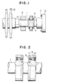
- a 12% Cr steel rotor 1 has a plurality of stages spaced in the axial direction, each stage having a multiplicity of moving blades 8 circumferentially arranged in an annular form.
- the rotor shaft 1 is supported at its journal portion by means of a journal bearing 3.
- Two thrust runners 4 axially spaced apart are formed integrally with the rotor shaft 1 and are positioned at both sides of a thrust bearing 5 adapted to receive the thrust acting on the rotor shaft 1.
- the 12% Cr steel rotor shaft 1 is provided at its one end with a coupling 6 formed integrally therewith.
- the coupling 6 has a plurality of coupling bolts 7 attached thereto.
- a sleeve 13 of a low alloy steel having a good bearing property is fitted around the journal portion of the 12% Cr steel rotor 1 facing the journal bearing 3, while a thrust runner protecting plate 9 of a low alloy steel having a good bearing property is provided on the thrust receiving side of each thrust runner 4 facing the thrust bearing 5.
- the 12% Cr steel rotor shaft 1 of the invention has a pair of disc-shaped thrust runners 4 as shown in Fig. 2, and the thrust bearing 5 is positioned between these runners 4.
- the thrust runner protecting plate 9 made of a low alloy steel having a good bearing property is attached by means of bolts 10 to the thrust-receiving side of each thrust runner 4.
- the thrust runner protecting plate 9 is formed of a low alloy steel containing as main components metals having a good bearing property such as chromium, molybdenum, vanadium or the like, and is beforehand worked and divided in the circumferential direction into two segments as shown in Fig. 3 so that the size and shape of the thrust runner protecting plate 9 may match the thrust supporting side of the double thrust runner.
- the thrust runner protecting plate 9 Since the thrust runner protecting plate 9 is divided into segments, it is possible to mount the same around the rotor shaft by securing each segment independently to the thrust receiving side of each thrust runner 4. Each segment of the thrust runner protecting plate 9 is provided with threaded holes 11 into which the bolts 10 are screwed to fix the segment to the thrust runner 4. After attaching two segments of the thrust runner protecting plate 9, the two segments are welded to each other at their joint surfaces 12, i.e. the slit surfaces, to form an integral annular thrust collar protecting member 9. This welding can be achieved by any desired welding method, however, the electron beam welding can be adopted most preferably.
- the electron beam welding permits the degassing of molten metal during welding, so that the weld metal is purified to ensure a good mechanical property of the weld zone.
- the electron beam welding can diminish the amount of correction work to be effected after the welding, because of small welding distortion.
- the segments of the thrust runner protecting plate 9 in the embodiment of the present invention are jointed to each other by the electron beam welding.
- the thrust runner protecting plate 9 integrated by the welding is finished smoothly regarding its external surfaces by mechanical working. In consequence, it is possible to obtain a thrust runner in which the thrust receiving side of the runner made of 12% Cr steel of poor friction property is protected by a thrust runner protecting plate 9 made of a low alloy steel having a good friction property. According to the invention, therefore, it is possible to obtain a 12% Cr steel rotor shaft capable of preventing the damage of the thrust bearing 5.
- a whole bainite steel containing, by weight, 0.2 to 2.25% of chromium and 0.2 to 1% of molybdenum is preferably used as the low alloy steel having good bearing property for the thrust runner protecting plate 9. More preferably, there is used another whole bainite steel further containing 0/05 to 0.5% by weight of vanadium in addition to the components of the former bainite steel.
- the low alloy steel used as the material of the thrust runner protecting plate offers the following advantage. Namely, this low alloy steel exhibits a thermal conductivity which is about 30% higher than that of the 12% Cr steel used as the material of the rotor shaft, so that the temperature rise of the protecting plate during operation of the turbine is much smaller than that of the thrust runner having no protecting plate.
- the material of the 12% Cr steel rotor shaft according to the invention is preferably a forged steel having whole martensite structure and consisting essentially of, by weight, 0.1 to 0.3% of C, not more than 0.6% of Si, 0.4 to 1.5% of Mn, not more than 1.2% of Ni, 8 to 14% of Cr, 0.5 to 1.5% of Mo, 0.05 to 0.3% of V, 0.02 to 0.15% of Nb and 0.04 to 0.1% of N and the balance Fe and inevitable impurities.
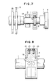
- Fig. 6 shows another thrust runner of a 12% Cr steel rotor shaft in accordance with another embodiment of the invention.
- This embodiment is discri- mianted from the first embodiment in the point that each thrust runner protecting plate 9 attached to the thrust receiving side of the thrust runner 4 is provided at the radially outer end thereof with an axially extending annular projection 15 at which the protecting plate 9 is secured to the thrust runner 4 by means of bolts 10.
- This embodiment is suited particularly for such a case where the axial thickness of the thrust runner protecting plate cannot be increased sufficiently due to a structural restriction, i.e. when it is not allowed to provide the threaded holes 11 in the radial plane of the thrust runner protecting plate 9.
- Fi g . 7 and 8 show another 12% Cr steel turbine rotor in accordance with still another embodiment of the invention.
- the rotor shaft of this embodiment is discriminated from the embodiments shown in Figs. 1 and 2 and Fig. 6 in its peculiar configuration of the single thrust runner 4.
- the rotor shaft 1 shown in Figs. 7 and 8 has a single disc-shaped thrust runner 4 formed integrally therewith.
- both axial end surfaces of this single thrust runner 4 constitute thrust receiving side in cooperation with a thrust bearing 5 which is disposed to ride on the thrust runner 4.
- a thrust runner protecting plate 9, made of the same low alloy steel used in tne preceding embodiments, is attached to each thrust receiving side of the single thrust runner 4.
- the thrust runner protecting plate 9 of this embodiment is composed of two segments each provided at the radially outer end thereof with axial projection 15. Two segments are secured to corresponding thrust-receiving side of the thrust runner 4 by means of bolts 10.
- the joint surfaces, i.e. the split surfaces, of two segments of each thrust runner protecting plate 9 are jointed to each other by the same electron beam welding as in the case of the second embodiment explained in connection with Fig. 6. It will be seen that this embodiment offers the same advantage as that derived from the second embodiment.
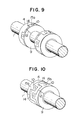
- Fig. 9 shows a still another rotor shaft in accordance with a further embodiment of the invention in which a plurality of recesses 14 extending in the axial direction of the rotor shaft are formed at a constant circumferential pitch in the radially outer end of the thrust receiving side of the thrust runner 4.
- the thrust runner protecting plate 9 made of a low alloy steel is provided at its outer peripheral portion with a plurality of projections 15b insertable in the recesses 14 at the same circumferential pitch as the recesses 14.
- Fig. 10 shows a still further embodiment in which the same configurations of the thrust runner and protecting plate as shown in Fig. 9 are applied to the single thrust runner shown in Fig. 7 having two thrust receiving surfaces. It will be clear to those skilled in the art that the embodiment shown in Fig. 10 offers the same advantage as that derived from the embodiment shown in Fig. 9.
- a thrust collar protecting member of a low alloy steel having a good bearing property is attached to the thrust receiving side of the thrust runner of a rotor shaft made of a 8 to 14% Cr steel which inherently has inferior bearing property but a superior high temperature strength and toughness, so that it is possible to obtain a rotor shaft having superior high temperature strength and toughness while achieving a good bearing property at the thrust runner thereof.
Landscapes
- Engineering & Computer Science (AREA)
- General Engineering & Computer Science (AREA)
- Mechanical Engineering (AREA)
- Ocean & Marine Engineering (AREA)
- Turbine Rotor Nozzle Sealing (AREA)
- Shafts, Cranks, Connecting Bars, And Related Bearings (AREA)
Applications Claiming Priority (2)
| Application Number | Priority Date | Filing Date | Title |
|---|---|---|---|
| JP101173/81 | 1981-07-01 | ||
| JP56101173A JPS585513A (ja) | 1981-07-01 | 1981-07-01 | クロム合金鋼製ロ−タシャフト |
Publications (2)
| Publication Number | Publication Date |
|---|---|
| EP0068496A1 true EP0068496A1 (fr) | 1983-01-05 |
| EP0068496B1 EP0068496B1 (fr) | 1985-02-20 |
Family
ID=14293610
Family Applications (1)
| Application Number | Title | Priority Date | Filing Date |
|---|---|---|---|
| EP82105780A Expired EP0068496B1 (fr) | 1981-07-01 | 1982-06-29 | Arbre de rotor en acier allié au chrome |
Country Status (3)
| Country | Link |
|---|---|
| EP (1) | EP0068496B1 (fr) |
| JP (1) | JPS585513A (fr) |
| DE (1) | DE3262418D1 (fr) |
Cited By (1)
| Publication number | Priority date | Publication date | Assignee | Title |
|---|---|---|---|---|
| WO2002063174A1 (fr) * | 2001-02-02 | 2002-08-15 | Delaware Capital Formation Inc. | Systeme de palier de butee |
Families Citing this family (3)
| Publication number | Priority date | Publication date | Assignee | Title |
|---|---|---|---|---|
| CN103697054B (zh) * | 2013-12-24 | 2016-01-13 | 于法周 | 一种旋转驱动棒棒体 |
| JP6634945B2 (ja) | 2016-04-19 | 2020-01-22 | 株式会社デンソー | 半導体モジュール |
| JP6760156B2 (ja) | 2017-03-20 | 2020-09-23 | 株式会社デンソー | 電力変換装置 |
Citations (2)
| Publication number | Priority date | Publication date | Assignee | Title |
|---|---|---|---|---|
| GB1095999A (en) * | 1964-05-28 | 1967-12-20 | Hawker Siddeley Canada Ltd | Improvements in fluid thrust bearing |
| EP0053515A1 (fr) * | 1980-12-02 | 1982-06-09 | Hitachi, Ltd. | Arbre de rotor |
-
1981
- 1981-07-01 JP JP56101173A patent/JPS585513A/ja active Granted
-
1982
- 1982-06-29 DE DE8282105780T patent/DE3262418D1/de not_active Expired
- 1982-06-29 EP EP82105780A patent/EP0068496B1/fr not_active Expired
Patent Citations (2)
| Publication number | Priority date | Publication date | Assignee | Title |
|---|---|---|---|---|
| GB1095999A (en) * | 1964-05-28 | 1967-12-20 | Hawker Siddeley Canada Ltd | Improvements in fluid thrust bearing |
| EP0053515A1 (fr) * | 1980-12-02 | 1982-06-09 | Hitachi, Ltd. | Arbre de rotor |
Cited By (1)
| Publication number | Priority date | Publication date | Assignee | Title |
|---|---|---|---|---|
| WO2002063174A1 (fr) * | 2001-02-02 | 2002-08-15 | Delaware Capital Formation Inc. | Systeme de palier de butee |
Also Published As
| Publication number | Publication date |
|---|---|
| JPS585513A (ja) | 1983-01-12 |
| DE3262418D1 (en) | 1985-03-28 |
| EP0068496B1 (fr) | 1985-02-20 |
| JPS6313043B2 (fr) | 1988-03-23 |
Similar Documents
| Publication | Publication Date | Title |
|---|---|---|
| US5237892A (en) | Reduced material crankshaft fabrication | |
| US6250883B1 (en) | Integral ceramic blisk assembly | |
| EP1967286B1 (fr) | Ensemble de stator encapsulé et processus de fabrication | |
| EP0556833B1 (fr) | Appareil de revêtement en continu par immersion et structure de palier à glissement | |
| EP1967288A2 (fr) | Ensembles de rotor et stator qui utilisent des supports magnétiques à utiliser dans des environnements corrosifs | |
| EP1967287A2 (fr) | Procédé pour tester un ensemble de rotor et de stator | |
| EP0717207A1 (fr) | Feuille élastique améliorant l'amortissement et la capacité de charge des paliers hydrodynamiques à feuilles souples | |
| EP1967289A2 (fr) | Ensemble d'arbre rotor pour supports magnétiques à utiliser dans des environnements corrosifs | |
| JP4502841B2 (ja) | 小型ローラベアリングを有するターボマシン | |
| JPS59101548A (ja) | 多重胴型タ−ビンエンジンの軸間軸受装置 | |
| JPS6049771B2 (ja) | テ−パ中空ころ | |
| US2922619A (en) | Turbine wheel assembly | |
| US4385787A (en) | Radial bearing for high-speed turbomachinery | |
| EP0053515B1 (fr) | Arbre de rotor | |
| EP0068496B1 (fr) | Arbre de rotor en acier allié au chrome | |
| US3517238A (en) | Squirrel cage rotor and method of building the same | |
| JPS63314372A (ja) | 水車の水潤滑軸受装置 | |
| US4318280A (en) | Dual property shaft | |
| WO2023280893A1 (fr) | Rotor pour machine électrique à grande vitesse | |
| JPH0260841B2 (fr) | ||
| EP0704028B1 (fr) | Agencement pour un montage independant de la temperature dans un palier | |
| JPS58178803A (ja) | タ−ビン軸 | |
| US3161446A (en) | Bearing pads | |
| EP0541680A1 (fr) | Paliers magnetiques. | |
| JPS6360244B2 (fr) |
Legal Events
| Date | Code | Title | Description |
|---|---|---|---|
| PUAI | Public reference made under article 153(3) epc to a published international application that has entered the european phase |
Free format text: ORIGINAL CODE: 0009012 |
|
| AK | Designated contracting states |
Designated state(s): DE GB |
|
| 17P | Request for examination filed |
Effective date: 19830308 |
|
| GRAA | (expected) grant |
Free format text: ORIGINAL CODE: 0009210 |
|
| AK | Designated contracting states |
Designated state(s): DE GB |
|
| REF | Corresponds to: |
Ref document number: 3262418 Country of ref document: DE Date of ref document: 19850328 |
|
| PLBI | Opposition filed |
Free format text: ORIGINAL CODE: 0009260 |
|
| 26 | Opposition filed |
Opponent name: ALSTHOM S.A. Effective date: 19851112 |
|
| PLBN | Opposition rejected |
Free format text: ORIGINAL CODE: 0009273 |
|
| STAA | Information on the status of an ep patent application or granted ep patent |
Free format text: STATUS: OPPOSITION REJECTED |
|
| 27O | Opposition rejected |
Effective date: 19870814 |
|
| PGFP | Annual fee paid to national office [announced via postgrant information from national office to epo] |
Ref country code: GB Payment date: 19940329 Year of fee payment: 13 |
|
| PGFP | Annual fee paid to national office [announced via postgrant information from national office to epo] |
Ref country code: DE Payment date: 19940630 Year of fee payment: 13 |
|
| PG25 | Lapsed in a contracting state [announced via postgrant information from national office to epo] |
Ref country code: GB Effective date: 19950629 |
|
| GBPC | Gb: european patent ceased through non-payment of renewal fee |
Effective date: 19950629 |
|
| PG25 | Lapsed in a contracting state [announced via postgrant information from national office to epo] |
Ref country code: DE Effective date: 19960301 |