EP0053651A1 - Soupape de réglage à pression fluide pour systèmes de freinage à deux circuits - Google Patents
Soupape de réglage à pression fluide pour systèmes de freinage à deux circuits Download PDFInfo
- Publication number
- EP0053651A1 EP0053651A1 EP81105153A EP81105153A EP0053651A1 EP 0053651 A1 EP0053651 A1 EP 0053651A1 EP 81105153 A EP81105153 A EP 81105153A EP 81105153 A EP81105153 A EP 81105153A EP 0053651 A1 EP0053651 A1 EP 0053651A1
- Authority
- EP
- European Patent Office
- Prior art keywords
- guide rod
- fluid pressure
- pressure control
- control apparatus
- housing
- Prior art date
- Legal status (The legal status is an assumption and is not a legal conclusion. Google has not performed a legal analysis and makes no representation as to the accuracy of the status listed.)
- Granted
Links
- 239000012530 fluid Substances 0.000 title claims abstract description 48
- 230000009977 dual effect Effects 0.000 title abstract description 3
- 230000010355 oscillation Effects 0.000 claims description 9
- 230000036316 preload Effects 0.000 claims description 3
- 230000000717 retained effect Effects 0.000 claims description 2
- 230000006835 compression Effects 0.000 description 7
- 238000007906 compression Methods 0.000 description 7
- 230000015572 biosynthetic process Effects 0.000 description 5
- 238000004519 manufacturing process Methods 0.000 description 4
- 230000000881 depressing effect Effects 0.000 description 3
- 230000002093 peripheral effect Effects 0.000 description 3
- 230000001276 controlling effect Effects 0.000 description 2
- 238000009825 accumulation Methods 0.000 description 1
- 230000003247 decreasing effect Effects 0.000 description 1
- 230000002950 deficient Effects 0.000 description 1
- 238000003754 machining Methods 0.000 description 1
- 238000000034 method Methods 0.000 description 1
- 230000002265 prevention Effects 0.000 description 1
- 230000001105 regulatory effect Effects 0.000 description 1
- 230000000630 rising effect Effects 0.000 description 1
- 230000001502 supplementing effect Effects 0.000 description 1
Images


Classifications
-
- B—PERFORMING OPERATIONS; TRANSPORTING
- B60—VEHICLES IN GENERAL
- B60T—VEHICLE BRAKE CONTROL SYSTEMS OR PARTS THEREOF; BRAKE CONTROL SYSTEMS OR PARTS THEREOF, IN GENERAL; ARRANGEMENT OF BRAKING ELEMENTS ON VEHICLES IN GENERAL; PORTABLE DEVICES FOR PREVENTING UNWANTED MOVEMENT OF VEHICLES; VEHICLE MODIFICATIONS TO FACILITATE COOLING OF BRAKES
- B60T8/00—Arrangements for adjusting wheel-braking force to meet varying vehicular or ground-surface conditions, e.g. limiting or varying distribution of braking force
- B60T8/26—Arrangements for adjusting wheel-braking force to meet varying vehicular or ground-surface conditions, e.g. limiting or varying distribution of braking force characterised by producing differential braking between front and rear wheels
-
- B—PERFORMING OPERATIONS; TRANSPORTING
- B60—VEHICLES IN GENERAL
- B60T—VEHICLE BRAKE CONTROL SYSTEMS OR PARTS THEREOF; BRAKE CONTROL SYSTEMS OR PARTS THEREOF, IN GENERAL; ARRANGEMENT OF BRAKING ELEMENTS ON VEHICLES IN GENERAL; PORTABLE DEVICES FOR PREVENTING UNWANTED MOVEMENT OF VEHICLES; VEHICLE MODIFICATIONS TO FACILITATE COOLING OF BRAKES
- B60T11/00—Transmitting braking action from initiating means to ultimate brake actuator without power assistance or drive or where such assistance or drive is irrelevant
- B60T11/10—Transmitting braking action from initiating means to ultimate brake actuator without power assistance or drive or where such assistance or drive is irrelevant transmitting by fluid means, e.g. hydraulic
- B60T11/28—Valves specially adapted therefor
- B60T11/34—Pressure reducing or limiting valves
Definitions
- This invention relates to a fluid pressure control apparatus including a pair of fluid pressure limiting valves or fluid pressure reducing valves to be used in a brake system of dual-circuit type wherein braking fluid pressure produced in a master cylinder is transmitted through a pair of mutually independent piping circuits to each of the rear wheels, right and left.
- a fluid pressure control apparatus in which a pair of valve plungers are disposed parallelly to each other in one housing with respective rear end protruding out of the housing and share one biasing device to be biased into the housing is already known by the United Kingdom patent specifications 1,531,803; 1,557,051; etc.
- Parallel plunger type control apparatuses of this kind are all defective in being too complicated in the structure of the biasing device, lacking operational stability, or producing strange noise or getting rid of some parts when the valve is forcibly vibrated as a whole. They have been anyway far from being fully satisfactory.
- a braking fluid pressure control apparatus including a pair of valve plungers disposed in parallel in one housing with respective rear end protruding out of the housing and means for biasing the rear ends into the housing, for controlling the braking fluid pressure produced in a master cylinder to be transmitted to each wheel brake disposed on a left rear wheel and a right rear wheel of a vehicle via two independent piping circuits; and the pressure control apparatus is characterized in that the biasing means comprises a guide rod retained at an intermediate position of the pair of valve plungers by a pivot pin oscillatably in a parallel direction to a plane including the axes of both plungers, a transmitting member provided with a tubular portion slidably fitted on the guide rod and an operating portion abuttable to the rear ends of the valve plungers, a spring for constantly imparting a predetermined biasing force to the rear ends of the valve plungers, and stopping means for limiting oscillation of the guide rod to an angular range having the center thereof on a straight
- the guide rod may be attached simply with a pivot pin to the housing or a member secured thereto, and the transmitting member also may be slidably fitted on a guide rod of a rod shape. It allows the manufacturing of the apparatus to be quite easy and operation of' the apparatus to be stable. Another merit of this invention resides in effective prevention of rattling in the fluid pressure control apparatus even when it is forcibly with vibrated, because the fitting clearance between the pivot pin and the guide rod as well as between the guide rod and the transmitting member can be minimized in this invention.
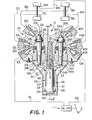
- a master cylinder 1 in Fig. 1 an equal amount of fluid pressure is generated in each of a first pressure producing chamber 4L and a second pressure producing chamber 4R in response to depressing of a brake pedal 2.
- the chamber 4L is connected via a conduit 6L to an inlet port 10L of a fluid pressure control apparatus 8, and further connected via a conduit 12L to a wheel cylinder 14L on a left front wheel and at the same time to a wheel cylinder 18R on a right rear wheel through a conduit 16L.
- the second pressure producing chamber 4R is in a similar way communicated via a conduit 6R to an inlet port 10R, and further via conduits 12R and 16R respectively to each wheel cylinder 14R, 18L on a right front wheel and a left rear wheel.
- the fluid pressure control apparatus 8 includes a pair of pressure reducing valves 26L, 26R sharing a housing 24 which consists of a main housing 20 and a pair of cylindrical members 22L, 22R.
- a housing 24 which consists of a main housing 20 and a pair of cylindrical members 22L, 22R.
- both pressure reducing valves 26L, 26R are of the entirely same structure, description will be limited only to one valve 26L, the other valve 26R being omitted of explanation by replacing the sign L by R in reference signs.
- the cylindrical member 22L In an opening of a blind hole formed in the main housing 20 the cylindrical member 22L is fixed by being screwed thereinto, and in a hollow portion of the cylindrical member 22L a.valve plunger 28L is pierced through.
- a seal member 30L is fitted into, which is covered in turn by a seal cover 32L.
- One end of the valve plunger 28L is formed into a valve 34L, adjacent to which a valve seat 36L is disposed.
- the inlet port 10L formed in the main housing 20 for being connected with the conduit 6L is, through an inlet chamber 38L and an outlet chamber 40L disposed on either side of the valve seat 36L, communicated to an outlet port 42L for a rear wheel brake. And the inlet port 10L is also only by way of the inlet chamber 38L communicated to an outlet port 44L for a front wheel brake.
- Those three ports 10L, 44L, and 42L are arranged almost radially assuming their center at the inlet chamber 38L, which makes the piping arrangement of the conduits connected to them quite easy, and the main housing 20 results in simultaneously functioning by the three ports 10L, 44L and 42L as a T-shape joint for divirging or branching off the conduits.
- a pair of plate-like support pieces 48 are formed intermediately between the two valve plungers 28L, 28R in a downward and mutually parallel posture.
- a head 52 of a guide rod 50 of round rod shape is rotatably connected with a pivot pin 54 in a parallel direction to a plane including the axes of the valve plungers 28L, 28R.
- the head 52 of the guide rod 50 is provided with a pair of planes formed perpendicular to the pivot pin 54 by a so-called method of taking two valid surfaces) the width from one plane to the other is so determined as to be just fitted between the pair of support pieces 48.
- On the end of the guide rod 50 oppo- .site from the head 52 a flange 55 is formed.
- the transmitting member 56 On the guide rod 50 the transmitting member 56 is slidably fitted in the axial direction of the guide rod 50.
- the transmitting member 56 is provided with a cylindrical portion 58 fitted on the guide ' rod 50 and an operating portion 60 applying force on both valve plungers 28L, 28R.
- the operating portion 60 is slantwise extended from one end of the cylindrical portion 58 on the side of the housing 24 along a plane including a central line of the cylindrical portion 58 toward the end of both valve plungers 28L, 28R so as to become a pair of arms.
- a pair of abutting surfaces 64L, 64R are formed parallelly faced to the lower surface of the housing 24 and to respectively abut on the end of the valve plungers 28L, 28R.
- Both abutting surfaces 64L, 64R respectively form a bottom surface of a pair of grooves 66L, 66R of rectangular shape in section which are longitudinally formed open upwards on the upper surface of either-end of the operating portion 60.
- the end of both valve plungers 28L, 28R is respectively fitted for preventing the transmitting member 56 from rotating about the guide rod 50.
- a compression coil spring 68 is disposed with a predetermined load, which being at one end thereof urged on a spring seat such as a washer 69 supported by the flange 55 of the guide rod 50 and at the other end on the operating portion 60 of the transmitting member 56.
- the valve plungers 28L, 28R are biased to a non-operating direction by the resilient force from the spring 68 which comes through the abutting surfaces 64L, 64R of the operating portion 60.
- the whole biasing device 46 is completely protected by a cover 70 secured to the main housing 20 with bolts.
- a stopper hole 72 is open rightly intermediate position between the axes of both valve plungers 28L, 28R.
- This stopper hole 72 is deeply formed in the main housing 20 parallelly to the valve plungers 28L, 28R. And the deepest portion thereof is made into a slightly diameter decreased portion, which is processed on the inner peripheral surface to a high degree precision to become a stopper surface 74.
- a stopper projection 76 which is a rod like member coaxially made with the guide rod 50 with a slightly smaller diameter than that of the guide rod 50.
- the stopper projection 76 is fitted into the stopper hole 72 formed in the main housing 20, and the peripheral portion of the end thereof is faced to the stopper surface 74 with an exact clearance a kept therebetween.
- This clearance a is relatively easy to exactly form and keep, because there arises little of accumulation of manufacturing errors due to the easy forming of the stopper hole 72 and the stopper projection 76, and the integral processing of the stopper projection 76 with the guide rod 50. And it can.be said a by-merit that formation of the stopper hole 72 in the housing 24 has contributed somewhat to weight reducing of the apparatus.
- the guide rod 50 is oscillatably or swingably attached with the pivot pin 54 to the main housing 20, and the transmitting member 56 is slidably fitted on the guide rod 50, which allows the transmitting member 56 to similarly make oscillation movement about the pivot pin 54. And the oscillation movement is limited within a minute angular range having its center on a straight line B which passes the axis of the pivot pin 54 and parallel to the valve plungers 28L, 28R. It is inevitable in this oscillation movement of the transmitting member 56 that the operating portion 60 is slightly moved in a perpendicular direction to the axes of the valve plungers 28L, 28R, so positioning of the pivot pin 54 are closely as possible to a straight line linking the tips of the valve plungers 28L, 28R is desirable.
- both valve plungers 28L, 28R urge downwards, against the biasing force of the compression coil spring 68, the transmitting member 56 to straight linearly move along the guide rod 50, followed by seating of the valves 34L, 34R on each of the valve seats 36L, 36R. After this seating both valve plungers 28L, 28R minutely move by inching until the force applied by the braking fluid pressure on the valve plungers 28L, 28R and the biasing force of the compression coil spring 68 are equilibrated so as to perform the well known fluid pressure reducing operation.
- valve plungers 28L, 28R should be primarily equal to each other, but a minute difference may arise between the two due to an error in manufacturing or another. This possible difference can be absorbed by a slight inclination of the transmitting member 56 made along with the guide rod 50.
- valve plunger 28R When therefore the fluid pressure in the outlet chamber 40R exceeds the predetermined value for the normal time the valve plunger 28R begins to move in a direction wherein the valve 34R is going to seat on the valve seat 36R.
- the transmitting member 56 which is urged at one abutting surface 64R thereof by the valve plunger 28R is gradually inclined, with the other abutting surface 64L being in an abutted condition on the end of the valve plunger 28L, so as to compress the compression coil spring 68. Further advancing of the inclination of the transmitting member 56 will cause the peripheral portion of the end of the stopper projection 76 to be abutted on the stopper surface 74 of the stopper hole 72 to prevent the guide rod 50 to be further inclined. At this stage the valve plunger 28R is not seated on the valve seat 36R yet.
- valve plunger 28R Further rising of the fluid pressure in the outlet chamber 40R causes the valve plunger 28R to urge the transmitting member 56 more strongly so that the same may be slided downwards on the guide rod 50 which has been prevented from inclination owing to the abutment of the stopper projection 76 on the stopper surface 74. At this time one abutting surface 64L of the transmitting member 56 is separated away from the end of the valve plunger 28L.
- valve 34R of the valve plunger 28R Upon arriving at this condition the valve 34R of the valve plunger 28R is seated on the valve seat 36R.
- valve plunger 28R in the one circuit damaged time is singly confronted to the biasing force of the spring 68, the transmitting member 56 which has been prevented from inclination by the abutment of the stopper projection 76 on the stopper surface 74 is not moved downwards unless fluid pressure two times as large as in the normal time is applied on the valve plunger 28R.
- the pressure reducing valve 26R does not begin the fluid pressure reducing operation before the fluid pressure in the outlet chamber 40R is approximately doubled. It means that the wheel cylinder 18L on the left rear wheel receives a far higher braking fluid pressure in comparison to the normal time.
- the stopper projection 76 and the stopper hole 72 are not necessarily required to be coaxially formed with the guide rod 50. They may be formed in a deviated status from the axis of the guide rod 50, so long as they are so located as to cross the axis of the pivot pin 54. Besides, formation of the stopper surface 74 by press- fitting of a ring into the stopper hole 72, or fitting of a ring on the end portion of the stopper projection 76 will make the exact determination of the clearance between the stopper projection 76 and the stopper surface quite easy, because highly precise processing or machining of either external periphery or internal periphery of the ring will suffice the condition.
- the stopper projection 76 may not necessarily be integrally made with the guide rod 50, but a separately made one is allowed -to be threaded on (or in) the guide rod 50.
- the guide rod 50 is not limited to a round rod shape, but it may be of prism shape if the cylindrical portion of the transmitting member 56 is reformed to a corresponding shape thereto. Formation of a rib(s) or groove(s) longitudinally formed on the guide rod 50 accompanied by the formation of supplementing groove(s) or rib(s) on the. transmitting member 56 for mutual engagement will be helpful in regulating the relative rotation between the two, with a by-merit of eliminating the formation of the grooves 66L, 66R on the transmitting member 56.
- a pair of plate-like support pieces 102 are formed intermediately between two valve plungers 28L, 28R in a downward and mutually parallel posture.
- a head 104 of a guide rod 106 of round rod shape is ro.tatably connected with a pivot pin 108 in a parallel direction to a plane including the axes of the valve plungers 28L, 28R.
- the head 104 of the guide rod 106 has a just fittable width between the pair of support pieces 102, and a pair of arms 110L, 110R extend in opposite direction one another therefrom, as shown in Fig. 3, in a perpendicular direction to the guide rod 106.
- the arms 110L, 110R having a groove of rectangular shape in section on the lower surface thereof extend along the lower or bottom surface 112 of the main housing 20 so as to be faced at the extreme end thereof to the lower surface 112 with an exact predetermined gap or distance 6 between the two.
- a pair of through holes 114L, 114R are formed respectively coaxially with the axes of the pair of valve plungers 28L, 28R which are parallel to each other. The end of those plungers is respectively piercing through those holes 114L, 114R so as to slightly project out of the lower surface of the arms 110L, 110R.
- the arms 110L, 110R and the guide rod 106 are integrally formed in this embodiment, which however may be separately formed.
- a transmitting member 116 consisting of a cylindrical portion 118 and an operating portion 120 threaded on the former at one end thereof, is axially slidably fitted.
- the operating portion 120 which is a plate-like member parallel to the lower surface 112 of the main housing 20 is provided on either end thereof with an upwardly erected projection 122L, 122R, which are respectively fitted into the grooves on the arms 110L, 110R for preventing the transmitting member 116 from being rotated about the guide rod 106 and being urged by the biasing force of a compression coil spring 124 onto the end of the valve plungers 28L, 28R.
- This compression coil spring 124 is mounted with a predetermined preload between the operating portion 120 of the transmitting member 116 and a ring 126 threaded on the end of the guide rod 106.
- the transmitting member 116 slidably fitted on the guide rod 106 which is rotatably connected to the main housing 20 with the pivot pin 108, is also rotatable about the pivot pin 108.
- This rotational movement or oscillation is limited to a minute or extremely small angular range, by virtue of a stopper mechanism 128 composed of the arms 110L, 110R and the lower surface 112 of the main housing 20 which are faced to each other having the exact gap S therebetween, having its center on a straight line parallel to the axes of the valve plungers 28L, 28R.
- the operating portion 120 is inevitably moved a little bit when the transmitting member 116 makes the rotational movement in a perpendicular direction to the axes of the valve plungers 28L, 28R, so the pivot pin 108 is desirable to be positioned for minimizing the movement amount of the operating portion 120 close to a straight line connecting the tip of the valve plungers 28L, 28R to the greatest possible extent.
- the biasing device 100 built as mentioned above is perfectly protected by a cover 130 secured to the main housing 20 with bolts.
- projections formed toward the housing on the arms 110L, 110R may be faced to projections formed on the housing 24 so as to abut each other.
- the projections on the arms may be the bolts erected by screwing on the arms 110L, 110R.
- FIG. 5 Another embodiment of this invention is illustrated in Fig. 5, wherein a compression coil spring 68 is set between a transmitting member 66 and a cover 70. Except the above-mentioned description of the coil spring 68, there are no differences between this embodiment and that shown in Figs. 1 and 2, all of the similar members being therefore allotted the same signs and numerals for omitting the superfluous explanation.
- the resilient force of the spring 68 being not applied on a pivot pin 54 in this embodiment, the size of the pivot pin 54 and support pieces 48 may be reduced and the distance between a pair of valve plungers 28L, 28R may be narrowed, which enables the apparatus to be made compact as a whole.
- a guide rod 50 can be lightly oscillable because of smallness of the friction force produced between the guide rod 50 and the pivot pin 54, which advantageously makes the difference of the initial pressures in a pair of pressure reducing valves 26L, 26R where the pressure reducing operation is started.
Landscapes
- Engineering & Computer Science (AREA)
- Transportation (AREA)
- Mechanical Engineering (AREA)
- Hydraulic Control Valves For Brake Systems (AREA)
Applications Claiming Priority (4)
| Application Number | Priority Date | Filing Date | Title |
|---|---|---|---|
| JP17656180U JPS6127321Y2 (fr) | 1980-12-09 | 1980-12-09 | |
| JP176561/80U | 1980-12-09 | ||
| JP19123080U JPS6211719Y2 (fr) | 1980-12-27 | 1980-12-27 | |
| JP191230/80U | 1980-12-27 |
Publications (2)
| Publication Number | Publication Date |
|---|---|
| EP0053651A1 true EP0053651A1 (fr) | 1982-06-16 |
| EP0053651B1 EP0053651B1 (fr) | 1985-09-25 |
Family
ID=26497428
Family Applications (1)
| Application Number | Title | Priority Date | Filing Date |
|---|---|---|---|
| EP81105153A Expired EP0053651B1 (fr) | 1980-12-09 | 1981-07-02 | Soupape de réglage à pression fluide pour systèmes de freinage à deux circuits |
Country Status (3)
| Country | Link |
|---|---|
| US (1) | US4401347A (fr) |
| EP (1) | EP0053651B1 (fr) |
| DE (1) | DE3172430D1 (fr) |
Cited By (3)
| Publication number | Priority date | Publication date | Assignee | Title |
|---|---|---|---|---|
| EP0184889A1 (fr) * | 1984-12-14 | 1986-06-18 | BENDIX ALTECNA S.p.A. | Dispositif égalisateur pour des correcteurs multiples de freinage asservis à la charge du véhicule |
| WO1990014975A3 (fr) * | 1989-06-10 | 1991-01-24 | Helmut Kollmeier | Systeme de freinage pour remorques a un seul essieu |
| EP0933273A1 (fr) | 1998-01-30 | 1999-08-04 | Bosch Systemes de Freinage | Compensateur double de freinage asservi à la charge d'un vehicule |
Families Citing this family (1)
| Publication number | Priority date | Publication date | Assignee | Title |
|---|---|---|---|---|
| US4753487A (en) * | 1986-11-28 | 1988-06-28 | Allied Corporation | Failure switch for braking system proportioning valve |
Citations (5)
| Publication number | Priority date | Publication date | Assignee | Title |
|---|---|---|---|---|
| DE2748699A1 (de) * | 1976-11-04 | 1978-05-11 | Automotive Prod Co Ltd | Bremsdruck-regulierventil |
| GB1531803A (en) * | 1975-04-01 | 1978-11-08 | Dba Sa | Braking correction device |
| GB1557051A (en) * | 1976-11-04 | 1979-12-05 | Automotive Prod Co Ltd | Fluid pressure limiting or reducing valves |
| GB2041474A (en) * | 1979-02-26 | 1980-09-10 | Teves Gmbh Alfred | Dual brake circuit pressure control unit |
| GB2048408A (en) * | 1979-03-20 | 1980-12-10 | Nissan Motor | Pressure control valve assembly for an automotive split brake system |
Family Cites Families (8)
| Publication number | Priority date | Publication date | Assignee | Title |
|---|---|---|---|---|
| US3459226A (en) * | 1966-12-22 | 1969-08-05 | Bendix Corp | Fluid pressure control valve |
| US3982795A (en) * | 1973-05-17 | 1976-09-28 | Graubremse Gmbh | Multi-circuit air-brake system, in particular for motor vehicles |
| GB1444397A (en) | 1973-07-16 | 1976-07-28 | Girling Ltd | Fluid pressure control valve |
| US4101176A (en) * | 1975-04-01 | 1978-07-18 | Societe Anonyme Dba | Braking correction device |
| JPS599382B2 (ja) * | 1977-02-18 | 1984-03-02 | 株式会社ナブコ | 2系統ブレ−キ用液圧制御弁 |
| JPS54109582A (en) * | 1978-02-16 | 1979-08-28 | Sumitomo Electric Ind Ltd | Two-system braking pressure-reducing valve |
| JPS5471272A (en) | 1977-11-17 | 1979-06-07 | Toyota Motor Corp | Hydraulic controlling device in two-system braking device |
| JPS55135661U (fr) * | 1979-03-20 | 1980-09-26 |
-
1981
- 1981-06-15 US US06/273,493 patent/US4401347A/en not_active Expired - Fee Related
- 1981-07-02 DE DE8181105153T patent/DE3172430D1/de not_active Expired
- 1981-07-02 EP EP81105153A patent/EP0053651B1/fr not_active Expired
Patent Citations (5)
| Publication number | Priority date | Publication date | Assignee | Title |
|---|---|---|---|---|
| GB1531803A (en) * | 1975-04-01 | 1978-11-08 | Dba Sa | Braking correction device |
| DE2748699A1 (de) * | 1976-11-04 | 1978-05-11 | Automotive Prod Co Ltd | Bremsdruck-regulierventil |
| GB1557051A (en) * | 1976-11-04 | 1979-12-05 | Automotive Prod Co Ltd | Fluid pressure limiting or reducing valves |
| GB2041474A (en) * | 1979-02-26 | 1980-09-10 | Teves Gmbh Alfred | Dual brake circuit pressure control unit |
| GB2048408A (en) * | 1979-03-20 | 1980-12-10 | Nissan Motor | Pressure control valve assembly for an automotive split brake system |
Cited By (4)
| Publication number | Priority date | Publication date | Assignee | Title |
|---|---|---|---|---|
| EP0184889A1 (fr) * | 1984-12-14 | 1986-06-18 | BENDIX ALTECNA S.p.A. | Dispositif égalisateur pour des correcteurs multiples de freinage asservis à la charge du véhicule |
| WO1990014975A3 (fr) * | 1989-06-10 | 1991-01-24 | Helmut Kollmeier | Systeme de freinage pour remorques a un seul essieu |
| EP0933273A1 (fr) | 1998-01-30 | 1999-08-04 | Bosch Systemes de Freinage | Compensateur double de freinage asservi à la charge d'un vehicule |
| FR2774342A1 (fr) | 1998-01-30 | 1999-08-06 | Bosch Syst Freinage | Compensateur double de freinage asservi a la charge d'un vehicule automobile |
Also Published As
| Publication number | Publication date |
|---|---|
| US4401347A (en) | 1983-08-30 |
| EP0053651B1 (fr) | 1985-09-25 |
| DE3172430D1 (en) | 1985-10-31 |
Similar Documents
| Publication | Publication Date | Title |
|---|---|---|
| US6047789A (en) | Toe angle adjustment mechanism for vehicle wheels | |
| US4401347A (en) | Fluid pressure control valve for dual braking system | |
| US4101176A (en) | Braking correction device | |
| US5660078A (en) | Yoke apparatus for rack and pinion | |
| JPS6137134B2 (fr) | ||
| US4053186A (en) | Proportional valve apparatus for use in a rear brake system of a vehicle | |
| JPS6211719Y2 (fr) | ||
| US4227746A (en) | Braking pressure control unit for a dual circuit brake system | |
| US4270807A (en) | Vehicle fluid pressure braking systems and lever mechanisms for use therein | |
| JPH0613023Y2 (ja) | 並列型プロポーシヨニングバルブ | |
| US4418964A (en) | Braking hydraulic pressure control valve in a dual-circuit brake system | |
| JPS6124434Y2 (fr) | ||
| JPS6127321Y2 (fr) | ||
| JPH0131578Y2 (fr) | ||
| JPS6211720Y2 (fr) | ||
| JPS6015500B2 (ja) | 車両用ブレ−キ油圧制御装置 | |
| US4353599A (en) | Braking corrector for double braking circuit | |
| JPH0130288Y2 (fr) | ||
| JP2538670Y2 (ja) | 荷重応答型液圧制御装置 | |
| JPS6124435Y2 (fr) | ||
| JPH0343498Y2 (fr) | ||
| JPH0133414Y2 (fr) | ||
| JPS6329639Y2 (fr) | ||
| JPS6211721Y2 (fr) | ||
| JPS6211724Y2 (fr) |
Legal Events
| Date | Code | Title | Description |
|---|---|---|---|
| PUAI | Public reference made under article 153(3) epc to a published international application that has entered the european phase |
Free format text: ORIGINAL CODE: 0009012 |
|
| AK | Designated contracting states |
Designated state(s): DE FR GB |
|
| 17P | Request for examination filed |
Effective date: 19820526 |
|
| RAP1 | Party data changed (applicant data changed or rights of an application transferred) |
Owner name: TOYOTA JIDOSHA KOGYO KABUSHIKI KAISHA |
|
| RAP1 | Party data changed (applicant data changed or rights of an application transferred) |
Owner name: TOYOTA JIDOSHA KABUSHIKI KAISHA |
|
| GRAA | (expected) grant |
Free format text: ORIGINAL CODE: 0009210 |
|
| AK | Designated contracting states |
Designated state(s): DE FR GB |
|
| REF | Corresponds to: |
Ref document number: 3172430 Country of ref document: DE Date of ref document: 19851031 |
|
| ET | Fr: translation filed | ||
| PLBE | No opposition filed within time limit |
Free format text: ORIGINAL CODE: 0009261 |
|
| STAA | Information on the status of an ep patent application or granted ep patent |
Free format text: STATUS: NO OPPOSITION FILED WITHIN TIME LIMIT |
|
| 26N | No opposition filed | ||
| PG25 | Lapsed in a contracting state [announced via postgrant information from national office to epo] |
Ref country code: GB Effective date: 19890702 |
|
| GBPC | Gb: european patent ceased through non-payment of renewal fee | ||
| PG25 | Lapsed in a contracting state [announced via postgrant information from national office to epo] |
Ref country code: FR Free format text: LAPSE BECAUSE OF NON-PAYMENT OF DUE FEES Effective date: 19900330 |
|
| PG25 | Lapsed in a contracting state [announced via postgrant information from national office to epo] |
Ref country code: DE Effective date: 19900403 |
|
| REG | Reference to a national code |
Ref country code: FR Ref legal event code: ST |