EP0053686A1 - Tauchkernspule mit einem Tauchkern - Google Patents
Tauchkernspule mit einem Tauchkern Download PDFInfo
- Publication number
- EP0053686A1 EP0053686A1 EP81108653A EP81108653A EP0053686A1 EP 0053686 A1 EP0053686 A1 EP 0053686A1 EP 81108653 A EP81108653 A EP 81108653A EP 81108653 A EP81108653 A EP 81108653A EP 0053686 A1 EP0053686 A1 EP 0053686A1
- Authority
- EP
- European Patent Office
- Prior art keywords
- winding
- plunger
- plunger core
- coil according
- core coil
- Prior art date
- Legal status (The legal status is an assumption and is not a legal conclusion. Google has not performed a legal analysis and makes no representation as to the accuracy of the status listed.)
- Granted
Links
- 238000004804 winding Methods 0.000 claims abstract description 64
- XEEYBQQBJWHFJM-UHFFFAOYSA-N Iron Chemical compound [Fe] XEEYBQQBJWHFJM-UHFFFAOYSA-N 0.000 claims abstract description 41
- 229910052742 iron Inorganic materials 0.000 claims abstract description 18
- 239000011810 insulating material Substances 0.000 claims abstract description 3
- 239000007769 metal material Substances 0.000 claims abstract description 3
- 239000004020 conductor Substances 0.000 claims description 6
- 238000003825 pressing Methods 0.000 claims description 6
- 229920003002 synthetic resin Polymers 0.000 claims description 3
- 239000000057 synthetic resin Substances 0.000 claims description 3
- 238000003475 lamination Methods 0.000 claims description 2
- 230000003068 static effect Effects 0.000 abstract 3
- 238000010276 construction Methods 0.000 description 3
- 238000007654 immersion Methods 0.000 description 3
- 239000002184 metal Substances 0.000 description 3
- 229910052751 metal Inorganic materials 0.000 description 3
- 238000011161 development Methods 0.000 description 2
- 230000018109 developmental process Effects 0.000 description 2
- 239000000463 material Substances 0.000 description 2
- 230000000712 assembly Effects 0.000 description 1
- 238000000429 assembly Methods 0.000 description 1
- 230000001066 destructive effect Effects 0.000 description 1
- 238000009826 distribution Methods 0.000 description 1
- 230000000694 effects Effects 0.000 description 1
- 230000001939 inductive effect Effects 0.000 description 1
- 238000009434 installation Methods 0.000 description 1
- 238000009413 insulation Methods 0.000 description 1
- 238000004519 manufacturing process Methods 0.000 description 1
- 238000010791 quenching Methods 0.000 description 1
- 230000000171 quenching effect Effects 0.000 description 1
Images
Classifications
-
- H—ELECTRICITY
- H01—ELECTRIC ELEMENTS
- H01F—MAGNETS; INDUCTANCES; TRANSFORMERS; SELECTION OF MATERIALS FOR THEIR MAGNETIC PROPERTIES
- H01F29/00—Variable transformers or inductances not covered by group H01F21/00
- H01F29/08—Variable transformers or inductances not covered by group H01F21/00 with core, coil, winding, or shield movable to offset variation of voltage or phase shift, e.g. induction regulators
- H01F29/10—Variable transformers or inductances not covered by group H01F21/00 with core, coil, winding, or shield movable to offset variation of voltage or phase shift, e.g. induction regulators having movable part of magnetic circuit
Definitions
- the invention relates to an adjustable inductor in plunger coil construction with only one axially arranged in the axial direction adjustable plunger in a winding on its outer sides covered by yoke legs and yokes of an iron circle with a circular cross-section.
- earth fault quenching coils The destructive effects of earth faults between live conductors and earth in electrical supply networks on components and devices that are only indirectly involved are usually mitigated or completely avoided through the use of inductors, so-called earth fault quenching coils.
- the earth leakage coils are matched to the earth capacitances of the electrical supply network to be protected in such a way that the capacitive earth leakage current is compensated by the inductive current at the earth leakage point. If the arc at the fault location does not go out due to the compensation, only relatively easily controllable residual currents flow there, consisting of the active current component of the earth leakage current, the leakage losses via the insulation against earth and the harmonic currents.
- Supply networks with variable expansion and therefore with different earth leakage currents are expediently equipped with continuously variable inductors in a plunger core design. Controlled by one Corresponding additional wiring, the inductance of the plunger core coil is set to the compensation current corresponding to the respective network state.
- the invention is therefore based on the object of providing an arrangement for plunger core coils of the type mentioned which works reliably despite a very simple construction and on the one hand largely uniformly loads the electromagnetically utilized material quantity of the active part on as many plunger core positions as possible and largely avoids eddy current losses in construction parts.
- this object is achieved by an arrangement in which a winding cylinder made of insulating material carrying the winding is firmly clamped in the immovable part of the iron circuit, in which the inside of the winding cylinder itself as a slideway and guide for the free end of the movable plunger immersed in the winding serves, in which all the end faces of the immersing end of the plunger core which are immersed in the winding lie outside the immovable part of the iron core outside the space covered by the winding and are at least approximately evenly distributed over the entire length of the winding in the partial cross-sections of the winding conductor.
- the plunger slides with synthetic resin runners on the inside of the winding cylinder and that the winding cylinder is guided by holding plates fitted on its outer jacket, which are at the same time pressure plates for the axial pressing of the winding and are in axial and radial Support direction on the core press.
- Advantageous embodiments of the invention also consist in the fact that the boundary surfaces of the immovable part of the iron circle which are opposite the end of the immersion core which is immersed in the winding lie in one plane, so that at least the ends of the sheet metal fins are glued together in the part of the immovable iron circle opposite the free end of the immersion core are and that the plunger core is composed of radially arranged metal plates.
- the immovable part of the iron circle consists of several yoke legs and upper ones connected to them and lower yoke stumps, the lower yoke stumps interlocking with coarse teeth.
- the end of the plunger protruding beyond the upper yoke stumps is guided between resiliently mounted rollers and that a spindle made of metallic material is mounted on one side for driving the plunger, which does not enter the main magnetic field between the plunger and the lower yokes protrudes or that the plunger is moved in that a built-in him cylinder contains a piston which is guided via a piston rod to the cover and can be acted upon hydraulically on both sides, or that the ickelzylinder of the W covered space is pressure-tightly sealed and the reeling cylinder serves as a hydraulic cylinder for the plunger formed as a hydraulic piston.
- the winding consists of a spirally wound film, the width of which is equal to the axial winding length, or the winding consists of winding groups which are arranged axially one above the other and are connected in parallel.
- the arrangement and configuration of a plunger core coil according to the invention is very advantageous because it enables the material used to be used evenly and the individual components and assemblies to be designed in a manner which is economical in terms of rational production. This is ensured in particular by dispensing with a second, stationary plunger core and by using the winding cylinder at the same time as a slideway and guide for the movable plunger core.
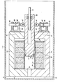
- the active part of a T core coil is set up in an oil-filled boiler 1.
- An iron circle of the active part consists of yoke legs 2, lower yokes 3, upper yokes 4 and an immersion core 5 and stands with feet 9 on the bottom of the boiler 1.
- the immovable part of the iron circle from the yoke legs 2 and the yokes 3 and 4 spatially comprises a winding arrangement of winding groups 6, which are axially superimposed on a winding cylinder 7.
- Four yoke legs 2 are evenly distributed over the circumference of the winding arrangement, the end faces of which are covered by the yokes 3 and 4 connected at right angles to the yoke legs 2.
- Both the yoke legs 2 and the yokes 3 and 4 are composed of laminations laminated in axially parallel planes, which are held together by a pressing device, not shown. To relieve this pressing device and at the same time to suppress noise, the ends of the sheet metal fins are glued together in the free ends of the yokes 3 and 4.
- the winding groups 6 encompassed by the immovable part of the iron circuit are electrically connected in parallel and all contain an equal number of turns.
- the cross sections of the conductors in the individual groups of windings 6 are practically each eilquerroughe merely as a T corresponding to the number of winding groups 6 split winding conductor.
- Forces acting on the winding groups 6 in the axial direction are generated by holding plates 8 added, which in turn are held in a manner not shown by the pressing device for the immovable part of the iron circle.
- winding groups 6 it is also possible to use a winding consisting of a spirally wound film, in which the film width is equal to the axial winding length.
- This so-called film winding is particularly useful in cases in which there are relatively low nominal voltages of the winding, so that only relatively few turns are to be provided and thus the space required for isolating the turns from one another does not lead to uneconomically low occupancy of the winding space with winding conductor itself.
- skids 10 made of synthetic resin which are inserted into recesses at the lower end of the plunger core 5 and are held in their installation position by a locking ring 11.
- the runners 10 protrude slightly in the radial direction from the contour of the preferably radially laminated plunger core 5 and thereby prevent direct contact between the surface of the plunger core 5 and the winding cylinder 7, which is conventionally made of hard paper.
- the plunger 5 passing through the opening between the free ends of the upper yokes 4 is guided above the yokes 4 between ball-bearing rollers 14, which are carried by guide bolts 13.
- the guide bolts 13, in turn, are mounted in bearing blocks 12 and press the ball-bearing rollers 14 by means of appropriately preloaded plate springs 16 against the T as well.
- the bearing blocks 12 are in a manner not shown, as are the holding plates 8 for the winding cylinder 7 with the pressing device connected to the immovable part of the iron circle.
- the mechanical drive of the plunger 5 is carried out via a spindle 17 with a trapezoidal thread, which does not protrude into the space between the plunger 5 and the lower yokes 3 and which is mounted only at the top, in order to avoid eddy current losses 18 engages.
- the free end of the spindle 17 is guided over the lid of the boiler 1 and coupled there with a preferably electric motor drive, which brings the plunger 5 into the required position within the winding arrangement and the immovable part of the iron core by rotating the threaded spindle 17.
- a preferably electric motor drive which brings the plunger 5 into the required position within the winding arrangement and the immovable part of the iron core by rotating the threaded spindle 17.
- the winding groups 6 flanking the air gap between the lower end of the plunger 5 and the lower yoke 3 are live, because the magnetic voltage drop occurs essentially in this area.
Landscapes
- Engineering & Computer Science (AREA)
- Power Engineering (AREA)
- Electromagnets (AREA)
- Breakers (AREA)
Abstract
Description
- Die Erfindung betrifft eine einstellbare Induktivität in Tauchkernspulenbauweise mit nur einem axial einseitig angeordneten in Achsrichtung verstellbaren Tauchkern in einer auf ihren Außenseiten von Rückschlußschenkeln und Jochen eines Eisenkreises umfaßten Wicklung mit kreisringförmigem Querschnitt.
- Zerstörerische Auswirkungen von Erdschlüssen zwischen Spannung führendenLeitern und Erde in elektrischen Versorgungsnetzen auf nur mittelbar beteiligte Bauteile und Geräte werden üblicherweise durch den Einsatz von Induktivitäten, sogenannten Erdschlußlöschspulen gemildert oder ganz vermieden. Die Erdschlußlpßchspulen werden auf die Erdkapazitäten des zu schützenden elektrischen Versorgungsnetzes so abgestimmt, daß an der Erdschlußstelle der kapazitive Erdschlußstrom durch den induktiven Strom kompensiert ist. Sofern der Lichtbogen an der Fehlerstelle durch die Kompensation nicht erlischt, fließen dort nur relativ leicht beherrschbare Restströme, bestehend aus dem Wirkstromanteil des Erdschlußstromes, den Ableitungsverlusten über die Isolierung gegen Erde und den Oberschwingungsströmen.
- Versorgungsnetze mit veränderlicher Ausdehnung und mit daher unterschiedlichem Erdschlußstrom werden zweckmäßigerweise mit stufenlos veränderbaren Induktivitäten in Tauchkernbauweise ausgerüstet. Gesteuert von einer entsprechenden zusätzlichen Beschaltung wird die Induktivität der Tauchkernspule auf den dem jeweiligen Netzzustand entsprechenden Kompensationsstrom eingestellt.
- In der bisher üblichen Bauweise für derartige Tauchkernspulen werden Anordnungen mit zwei Tauchkernen verwendet, von denen einer in einer mittleren Stellung fest eingebaut und der andere zwischen Grenzwerten in Achsrichtung verschiebbar ist. Durch Verschieben dieses einen Tauchkerns wird der Abstand der beiden Tauchkerne'voneinander und damit die Größe der Induktivität der Tauchkernspule insgesamt verändert. Nachteilig ist bei dieser Anordnung, daß der fest eingebaute Tauchkern unabhängig von der jeweiligen Einstellung in die Wicklung hineinragt und dadurch besonders in den Tauchkerneinstellungen für niedrige Ströme eine ungünstige magnetische Feldverteilung hervorruft und damit eine ungünstige Beaufschlagung des Eisenkernes zur Folge hat. Nachteilig ist weiterhin, daß dabei die metallische Spindel zur Bewegung des oberen Tauchkernes bis in den unteren feststehenden Kernstumpf geführt ist und bei ausgezogenem oberen Tauchkern dem Hauptmagnetfeld ausgesetzt und dadurch mit hohen Wirbelstromverlusten behaftet ist.
- Der Erfindung liegt daher die Aufgabe zugrunde, für Tauchkernspulen der eingangs genannten Art eine Anordnung zu schaffen, die trotz sehr einfachem Aufbau betriebssicher arbeitet und dabei einerseits die elektromagnetisch ausgenutzte Werkstoffmenge des Aktivteils auf möglichst vielen Tauchkernstellungen weitgehend gleichmäßig belastet und Wirbelstromverluste in Konstruktionsteilen weitgehend vermeidet.
- Erfindungsgemäß wird diese Aufgabe durch eine Anordnung gelöst, bei der ein die Wicklung tragender Wickelzylinder aus Isolierwerkstoff in den unbeweglichen Teil des Eisenkreises fest eingespannt ist, bei der die Innenseite des Wickelzylinders selbst als Gleitbahn und Führung für das in die Wicklung eintauchende freie Ende des beweglichen Tauchkernes dient, bei der alle der Stirnseite des in die Wicklung eintauchenden Endes dieses Tauchkernes gegenüberliegende Begrenzungsflächen des unbeweglichen Teiles des Eisenkernes außerhalb des von der Wicklung umfaßten Raumes liegen und bei der Teilquerschnitte des Wickelleiters jeder Windung wenigstens annähernd gleichmäßig über die gesamte Wicklungslänge verteilt sind.
- Nach zweckmäßigen Weiterbildungen der Erfindung ist vorgesehen, daß der Tauchkern mit Kufen aus Kunstharz auf der Innenseite des Wickelzylinders gleitet und daß der Wickelzylinder durch auf seinen Außenmantel aufgepaßte Halteplatten geführt ist, die gleichzeitig Druckplatten für die axiale Pressung der Wicklung sind und sich in axialer und radialer Richtung an der Kernpreßeinrichtung abstützen.
- Vorteilhafte Ausgestaltungen der Erfindung bestehen auch darin, daß die dem in die Wicklung eintauchenden Ende des Tauchkernes gegenüberliegenden Begrenzungsflächen des unbeweglichen Teiles des Eisenkreises in einer Ebene liegen, daß mindestens die Enden der Blechlamellen in dem dem freien Ende des Tauchkernes gegenüberliegenden Teil des unbeweglichen Eisenkreises miteinander verklebt sind und daß der Tauchkern aus radial angeordneten Blechlamellen zusammengsetzt ist. Dabei besteht der unbewegliche Teil des Eisenkreises aus mehreren Rückschlußschenkeln und mit diesen verbundenen oberen und unteren Jochstümpfen, wobei die unteren Jochstümpfe mit grober Verzahnung ineinandergreifen.
- Nach weiteren Ausgestaltungsmerkmalen der Erfindung ist vorgesehen, daß das über die oberen Jochstümpfe hinausragende Ende des Tauchkernes zwischen federnd gelagerten Rollen geführt ist und daß zum Antrieb des Tauchkerns eine einseitig gelagerte Spindel aus metallischem Werkstoff vorgesehen ist, die nicht in das Hauptmagnetfeld zwischen Tauchkern und unteren Jochen hineinragt, oder daß der Tauchkern dadurch bewegt wird, daß ein in ihn eingebauter Zylinder einen Kolben enthält, der über eine Kolbenstange zum Deckel geführt ist und hydraulisch beidseitig beaufschlagt werden kann, oder daß der von dem Wickelzylinder umfaßte Raum druckdicht verschlossen ist und der Wickelzylinder als Hydraulikzylinder für den als Hydraulikkolben ausgebildeten Tauchkern dient.
- Nach anderen zweckmäßigen Weiterbildungen der Erfindung besteht die Wicklung aus spiralig aufgewickelter Folie, deren Breite gleich der axialen Wicklungslänge ist oder besteht die Wicklung aus axial übereinander angeordneten elektrisch parallel geschalteten Wicklungsgruppen.
- Die erfindungsgemäße Anordnung und Ausgestaltung einer Tauchkernspule ist sehr vorteilhaft, denn sie ermöglicht eine gleichmäßige Ausnutzung des eingesetzten Werkstoffes und eine im Sinne einer rationellen Fertigung günstige Gestaltung der einzelnen Bauteile und Baugruppen. Dies ist insbesondere durch den Verzicht auf einen zweiten, feststehenden Tauchkern und die Verwendung des Wickelzylinders gleichzeitig als Gleitbahn und Führung für den beweglichen Tauchkern gewährleistet.
- Ein Ausführungsbeispiel der Erfindung wird anhand einer Zeichnung näher erläutert.
- In einem ölgefüllten Kessel 1 ist der Aktivteil einer Tauchkernspule aufgestellt. Ein Eisenkreis des Aktivteiles besteht aus Rückschlußschenkeln 2, unteren Jochen 3, oberen Jochen 4 sowie einem Tauchkern 5 und steht mit Füßen 9 auf dem Boden des Kessels 1.
- Der unbewegliche Teil des Eisenkreises aus den Rückschlußschenkeln 2 sowie den Jochen 3 und 4 umfaßt räumlich eine Wicklungsanordnung aus Wicklungsgruppen 6, die axial übereinander fest auf einen Wickelzylinder 7 aufgebracht sind. Dabei sind vier Rückschlußschenkel 2 gleichmäßig auf den Umfang der Wicklungsanordnung verteilt, deren Stirnseiten von den rechtwinkelig mit den Rückschlußschenkeln 2 verbundenen Jochen 3 und 4 überdeckt werden.
- Die freien Enden der unteren Joche 3 sind stufenförmig ausgebildet und greifen mit grober Verzahnung ineinander. Sowohl die Rückschlußschenkel 2 als auch die Joche 3 und 4 sind aus in achsparallelen Ebenen geschichteten Blechlamellen zusammengesetzt, die durch eine nicht näher dargestellte Preßvorrichtung zusammengehalten sind. Zur Entlastung dieser Preßvorrichtung und gleichzeitig zur Unterdrückung von Geräuschen sind die Enden der Blechlamellen in den freien Enden der Joche 3 und 4 miteinander verklebt.
- Die von dem unbeweglichen Teil des Eisenkreises umfaßten Wicklungsgruppen 6 sind elektrisch parallel geschaltet und enthalten alle eine gleiche Anzahl von Windungen. Durch die elektrische Parallelschaltung sind praktisch die Querschnitte der Leiter in den einzelnen Wicklungsgruppen 6 jeweils lediglich als Teilquerschnitte eines entsprechend der Anzahl von Wicklungsgruppen 6 aufgeteilten Wickelleiters. In Achsrichtung auf die Wicklungsgruppen 6 einwirkende Kräfte werden von Halteplatten 8 aufgenommen, die ihrerseits in nicht dargestellter Weise von der Preßvorrichtung für den unbeweglichen Teil des Eisenkreises gehalten sind.
- Anstelle der dargestellten Wicklungsanordnung aus Wicklungsgruppen 6 kann auch eine aus einer spiralig aufgewickelten Folie bestehende Wicklung eingesetzt werden, in der die Folienbreite gleich der axialen Wicklungslänge ist. Diese sogenannte Folienwicklung ist besonders in den Fällen zweckmäßig, in denen verhältnismäßig kleine Nennspannungen der Wicklung vorhanden sind, so daß nur relativ wenige Windungen vorzusehen sind und damit der zur Isolierung der Windungen voneinander erforderliche Raum nicht zu unwirtschaftlich niedriger Belegung des Wickelraumes mit Wickelleiter selbst führt.
- Der in die beim dargestellten Ausführungsbeispiel in die Wicklungsanordnung aus den Wicklungsgruppen 6 eintauchende Tauchkern 5 ist an seinem unteren Ende unmittelbar von der Innenseite des Wickelzylinders 7 geführt. Dabei dienen zur Verminderung der Reibkräfte und der hierzu proportionalen Verschleißerscheinungen Kufen 10 aus Kunstharz, die in Aussparungen am unteren Ende des Tauchkernes 5 eingesetzt sind und durch einen Sicherungsring 11 in ihrer Einbaulage festgehalten sind. Die Kufen 10 ragen in radialer Richtung geringfügig aus der Kontur des vorzugsweise radial geblechten Tauchkernes 5 heraus und verhindern dadurch unmittelbare Berührungen zwischen der Oberfläche des Tauchkernes 5 und dem in üblicher Weise aus Hartpapier hergestellten Wickelzylinder 7.
- Der die öffnung zwischen den freien Enden der oberen Joche 4 durchsetzende Tauchkern 5 ist oberhalb der Joche 4 zwischen kugelgelagerten Rollen 14 geführt, die von Führungsbolzen 13 getragen sind. Die Führungsbolzen 13 ihrerseits sind in Lagerböcken 12 gelagert und drücken die kugelgelagerten Rollen 14 durch entsprechend vorgespannte.Tellerfedern 16 gegen den Tauch- kern 5. Die Lagerböcke 12 sind in nicht näher dargestellter Weise ebenso wie die Halteplatten 8 für den Wickelzylinder 7 mit der Preßvorrichtung für den unbeweglichen Teil des Eisenkreises verbunden.
- Der mechanische Antrieb des Tauchkernes 5 erfolgt über eine nur oben gelagerte, zur Vermeidung von Wirbelstromverlusten nicht in den Raum zwischen dem Tauchkern 5 und den unteren Jochen 3 hineinragende Spindel 17 mit Trapezgewinde, die in eine-entsprechend gestaltete und fest in den Tauchkern 5 eingepaßte Mutter 18 eingreift. Das freie Ende der Spindel 17 ist bis über den Deckel des Kessels 1 geführt und dort mit einem vorzugsweise elektromotorischen Antrieb gekuppelt, der durch Drehen der Gewindespindel 17 den Tauchkern 5 in die jeweils erforderliche Stellung innerhalb der Wicklungsanordnung und dem unbeweglichen Teil des Eisenkernes bringt. Dabei sind im wesentlichen lediglich die den Luftspalt zwischen dem unteren Ende des Tauchkernes 5 und dem unteren Joch 3 flankierenden Wicklungsgruppen 6 stromführend, weil der magnetische Spannungsfall im wesentlichen in diesem Bereich auftritt.
Claims (10)
Priority Applications (1)
| Application Number | Priority Date | Filing Date | Title |
|---|---|---|---|
| AT81108653T ATE11838T1 (de) | 1980-12-05 | 1981-10-21 | Tauchkernspule mit einem tauchkern. |
Applications Claiming Priority (2)
| Application Number | Priority Date | Filing Date | Title |
|---|---|---|---|
| DE3045954 | 1980-12-05 | ||
| DE19803045954 DE3045954A1 (de) | 1980-12-05 | 1980-12-05 | Tauchkernspule mit einem tauchkern |
Publications (2)
| Publication Number | Publication Date |
|---|---|
| EP0053686A1 true EP0053686A1 (de) | 1982-06-16 |
| EP0053686B1 EP0053686B1 (de) | 1985-02-13 |
Family
ID=6118441
Family Applications (1)
| Application Number | Title | Priority Date | Filing Date |
|---|---|---|---|
| EP81108653A Expired EP0053686B1 (de) | 1980-12-05 | 1981-10-21 | Tauchkernspule mit einem Tauchkern |
Country Status (3)
| Country | Link |
|---|---|
| EP (1) | EP0053686B1 (de) |
| AT (1) | ATE11838T1 (de) |
| DE (1) | DE3045954A1 (de) |
Cited By (1)
| Publication number | Priority date | Publication date | Assignee | Title |
|---|---|---|---|---|
| EP3796349A1 (de) * | 2019-09-20 | 2021-03-24 | Siemens Energy Global GmbH & Co. KG | Drosselspule mit verstellbarem eisenkern |
Families Citing this family (2)
| Publication number | Priority date | Publication date | Assignee | Title |
|---|---|---|---|---|
| DE3730462A1 (de) * | 1987-09-10 | 1989-03-23 | Siemens Ag | Einstellbare induktivitaet mit einem axial einseitig angeordneten tauchkern |
| AT515723A1 (de) * | 2014-04-30 | 2015-11-15 | Trench Austria Gmbh | Tauchkernspule, Gewindespindel hiefür und Verfahren zu deren Herstellung |
Citations (11)
| Publication number | Priority date | Publication date | Assignee | Title |
|---|---|---|---|---|
| DE317728C (de) * | ||||
| DE728973C (de) * | 1937-12-01 | 1942-12-07 | Siemens Ag | Regeltransformator oder Regeldrosselspule fuer Mehrstellen-Lichtbogenschweissung |
| US2437021A (en) * | 1945-10-06 | 1948-03-02 | Fries Eduard | Transformer with regulatable leakage reactance |
| DE1052569B (de) * | 1954-10-14 | 1959-03-12 | Zahnradfabrik Friedrichshafen | Elektromagnet |
| DE1247480B (de) * | 1960-11-07 | 1967-08-17 | Elin Union Ag | Hydraulisch verstellbare Tauchkern-Drosselspule |
| DE1488841A1 (de) * | 1964-12-30 | 1969-04-10 | Elin Union Ag | Tauchkernspule |
| DE1514505A1 (de) * | 1965-07-12 | 1970-11-12 | Siemens Ag | Abgleichvorrichtung von elektrischen Schalenkernspulen |
| DE1638471A1 (de) * | 1967-06-05 | 1971-06-03 | Mo Elektrosawod Im Kuibyschewa | Drosselspule fuer den Hochspannungsbereich |
| FR2315753A1 (fr) * | 1975-06-27 | 1977-01-21 | Cit Alcatel | Bobinage a inductance reglable |
| FR2335922A1 (fr) * | 1975-12-18 | 1977-07-15 | Selam Gabriel | Inductance et son procede de fabrication |
| DE2359999B2 (de) * | 1973-12-01 | 1979-03-01 | Samuil Chononovitsch Schtschutschinskij | Elektromagnet zur Betätigung eines Stellglieds |
Family Cites Families (6)
| Publication number | Priority date | Publication date | Assignee | Title |
|---|---|---|---|---|
| DE506657C (de) * | 1930-09-08 | Aeg | Regelbare Drosselspule mit einem innerhalb der Wicklung in axialer Richtung verschiebbaren, durch mehrere Luftspalte unterteilten Eisenkern | |
| US2364291A (en) * | 1940-10-30 | 1944-12-05 | Rca Corp | Intermediate frequency transformer |
| US2727149A (en) * | 1950-08-19 | 1955-12-13 | Rca Corp | Balanced multisection inductance units for high frequency signal systems and the like |
| US2731608A (en) * | 1952-02-29 | 1956-01-17 | Collins Radio Co | Inductance corrector |
| DE1001755B (de) * | 1955-11-25 | 1957-01-31 | Licentia Gmbh | Hydraulisch regelbare Tauchkerndrosselspule |
| US3609614A (en) * | 1969-12-29 | 1971-09-28 | Hipotronics | Mechanically variable high reactive power inductor for testing capacitive loads,such as high voltage electrical power transmission cables |
-
1980
- 1980-12-05 DE DE19803045954 patent/DE3045954A1/de active Granted
-
1981
- 1981-10-21 AT AT81108653T patent/ATE11838T1/de not_active IP Right Cessation
- 1981-10-21 EP EP81108653A patent/EP0053686B1/de not_active Expired
Patent Citations (11)
| Publication number | Priority date | Publication date | Assignee | Title |
|---|---|---|---|---|
| DE317728C (de) * | ||||
| DE728973C (de) * | 1937-12-01 | 1942-12-07 | Siemens Ag | Regeltransformator oder Regeldrosselspule fuer Mehrstellen-Lichtbogenschweissung |
| US2437021A (en) * | 1945-10-06 | 1948-03-02 | Fries Eduard | Transformer with regulatable leakage reactance |
| DE1052569B (de) * | 1954-10-14 | 1959-03-12 | Zahnradfabrik Friedrichshafen | Elektromagnet |
| DE1247480B (de) * | 1960-11-07 | 1967-08-17 | Elin Union Ag | Hydraulisch verstellbare Tauchkern-Drosselspule |
| DE1488841A1 (de) * | 1964-12-30 | 1969-04-10 | Elin Union Ag | Tauchkernspule |
| DE1514505A1 (de) * | 1965-07-12 | 1970-11-12 | Siemens Ag | Abgleichvorrichtung von elektrischen Schalenkernspulen |
| DE1638471A1 (de) * | 1967-06-05 | 1971-06-03 | Mo Elektrosawod Im Kuibyschewa | Drosselspule fuer den Hochspannungsbereich |
| DE2359999B2 (de) * | 1973-12-01 | 1979-03-01 | Samuil Chononovitsch Schtschutschinskij | Elektromagnet zur Betätigung eines Stellglieds |
| FR2315753A1 (fr) * | 1975-06-27 | 1977-01-21 | Cit Alcatel | Bobinage a inductance reglable |
| FR2335922A1 (fr) * | 1975-12-18 | 1977-07-15 | Selam Gabriel | Inductance et son procede de fabrication |
Cited By (1)
| Publication number | Priority date | Publication date | Assignee | Title |
|---|---|---|---|---|
| EP3796349A1 (de) * | 2019-09-20 | 2021-03-24 | Siemens Energy Global GmbH & Co. KG | Drosselspule mit verstellbarem eisenkern |
Also Published As
| Publication number | Publication date |
|---|---|
| DE3045954A1 (de) | 1982-07-08 |
| ATE11838T1 (de) | 1985-02-15 |
| EP0053686B1 (de) | 1985-02-13 |
| DE3045954C2 (de) | 1991-12-12 |
Similar Documents
| Publication | Publication Date | Title |
|---|---|---|
| DE69728972T2 (de) | Transformator/reactor | |
| DE68920962T2 (de) | Transformatorwicklung, aufgebaut als eine Scheibenwicklung mit axialen Kanälen. | |
| EP0117460A1 (de) | Drehstromdrosselspule mit Fünfschenkelkern | |
| DE2002192B2 (de) | Transformator, drosselspule oder dgl. induktionsgeraete fuer hohe betriebsspannung | |
| DE2709300B2 (de) | Supraleitende Magnetspule mit Imprägniereinrichtung | |
| EP1725420B1 (de) | Magnetanordnung für trag-, für- und/oder bremssysteme bei magnetschwebefahrzeugen | |
| EP0053686B1 (de) | Tauchkernspule mit einem Tauchkern | |
| DE2953100C1 (de) | Hochspannungs-Transformations- und Gleichrichtereinrichtung | |
| DE2226512C3 (de) | Filterkreisdrossel | |
| DE1293334B (de) | Eisenkernlose Hoechstspannungs-Nebenschlussdrossel | |
| DE2154398C3 (de) | Spannungstransformator zur vertikalen Aufstellung mit einem gestreckten Magnetkern | |
| DE723560C (de) | Transformator | |
| DE3730462C2 (de) | ||
| DE643404C (de) | Einrichtung zum Unterbrechen von Hochleistungswechselstromkreisen | |
| EP0127119A1 (de) | Elektromagnetisches Gerät für mit Hochfrequenz betriebene Leistungsstromkreise, insbesondere Transformator oder Drosselspule | |
| EP3420570B1 (de) | Elektrisches hochspannungsgerät mit einer regelwicklungsgruppe | |
| CH208632A (de) | Anordnung zur Schliessung und Unterbrechung eines Wechselstromkreises. | |
| DE2934719A1 (de) | In vergussbauweise hergestellter transformator | |
| EP0166952B1 (de) | Hochstromtransformator mit indirekter Spannungseinstellung über einen Zwischenkreis | |
| DE4333185C2 (de) | Wicklungsanordnung | |
| DE1057219B (de) | Mittel- und Hochfrequenz-Leistungstransformator | |
| DE3744436C2 (de) | ||
| DE3326422C2 (de) | ||
| DE3040412C2 (de) | Wicklungsanordnung für Transformatoren | |
| DE10246543A1 (de) | Wicklungsanordnung |
Legal Events
| Date | Code | Title | Description |
|---|---|---|---|
| PUAI | Public reference made under article 153(3) epc to a published international application that has entered the european phase |
Free format text: ORIGINAL CODE: 0009012 |
|
| 17P | Request for examination filed |
Effective date: 19811021 |
|
| AK | Designated contracting states |
Designated state(s): AT CH LI NL SE |
|
| GRAA | (expected) grant |
Free format text: ORIGINAL CODE: 0009210 |
|
| AK | Designated contracting states |
Designated state(s): AT CH LI NL SE |
|
| REF | Corresponds to: |
Ref document number: 11838 Country of ref document: AT Date of ref document: 19850215 Kind code of ref document: T |
|
| PLBE | No opposition filed within time limit |
Free format text: ORIGINAL CODE: 0009261 |
|
| STAA | Information on the status of an ep patent application or granted ep patent |
Free format text: STATUS: NO OPPOSITION FILED WITHIN TIME LIMIT |
|
| 26N | No opposition filed | ||
| PGFP | Annual fee paid to national office [announced via postgrant information from national office to epo] |
Ref country code: CH Payment date: 19950118 Year of fee payment: 14 |
|
| EAL | Se: european patent in force in sweden |
Ref document number: 81108653.7 |
|
| PGFP | Annual fee paid to national office [announced via postgrant information from national office to epo] |
Ref country code: AT Payment date: 19950920 Year of fee payment: 15 |
|
| PGFP | Annual fee paid to national office [announced via postgrant information from national office to epo] |
Ref country code: NL Payment date: 19951017 Year of fee payment: 15 |
|
| PGFP | Annual fee paid to national office [announced via postgrant information from national office to epo] |
Ref country code: SE Payment date: 19951019 Year of fee payment: 15 |
|
| PG25 | Lapsed in a contracting state [announced via postgrant information from national office to epo] |
Ref country code: LI Effective date: 19951031 Ref country code: CH Effective date: 19951031 |
|
| REG | Reference to a national code |
Ref country code: CH Ref legal event code: PL |
|
| PG25 | Lapsed in a contracting state [announced via postgrant information from national office to epo] |
Ref country code: AT Effective date: 19961021 |
|
| PG25 | Lapsed in a contracting state [announced via postgrant information from national office to epo] |
Ref country code: SE Effective date: 19961022 |
|
| PG25 | Lapsed in a contracting state [announced via postgrant information from national office to epo] |
Ref country code: NL Effective date: 19970501 |
|
| NLV4 | Nl: lapsed or anulled due to non-payment of the annual fee |
Effective date: 19970501 |
|
| EUG | Se: european patent has lapsed |
Ref document number: 81108653.7 |