EP0053739A1 - Federgefüge - Google Patents
Federgefüge Download PDFInfo
- Publication number
- EP0053739A1 EP0053739A1 EP81109671A EP81109671A EP0053739A1 EP 0053739 A1 EP0053739 A1 EP 0053739A1 EP 81109671 A EP81109671 A EP 81109671A EP 81109671 A EP81109671 A EP 81109671A EP 0053739 A1 EP0053739 A1 EP 0053739A1
- Authority
- EP
- European Patent Office
- Prior art keywords
- coils
- rows
- interconnecting segments
- spring assembly
- axes
- Prior art date
- Legal status (The legal status is an assumption and is not a legal conclusion. Google has not performed a legal analysis and makes no representation as to the accuracy of the status listed.)
- Granted
Links
Images


Classifications
-
- A—HUMAN NECESSITIES
- A47—FURNITURE; DOMESTIC ARTICLES OR APPLIANCES; COFFEE MILLS; SPICE MILLS; SUCTION CLEANERS IN GENERAL
- A47C—CHAIRS; SOFAS; BEDS
- A47C23/00—Spring mattresses with rigid frame or forming part of the bedstead, e.g. box springs; Divan bases; Slatted bed bases
- A47C23/04—Spring mattresses with rigid frame or forming part of the bedstead, e.g. box springs; Divan bases; Slatted bed bases using springs in compression, e.g. coiled
- A47C23/043—Spring mattresses with rigid frame or forming part of the bedstead, e.g. box springs; Divan bases; Slatted bed bases using springs in compression, e.g. coiled using wound springs
- A47C23/0436—Spring mattresses with rigid frame or forming part of the bedstead, e.g. box springs; Divan bases; Slatted bed bases using springs in compression, e.g. coiled using wound springs made from a single wire
-
- A—HUMAN NECESSITIES
- A47—FURNITURE; DOMESTIC ARTICLES OR APPLIANCES; COFFEE MILLS; SPICE MILLS; SUCTION CLEANERS IN GENERAL
- A47C—CHAIRS; SOFAS; BEDS
- A47C23/00—Spring mattresses with rigid frame or forming part of the bedstead, e.g. box springs; Divan bases; Slatted bed bases
- A47C23/04—Spring mattresses with rigid frame or forming part of the bedstead, e.g. box springs; Divan bases; Slatted bed bases using springs in compression, e.g. coiled
- A47C23/05—Frames therefor; Connecting the springs to the frame ; Interconnection of springs, e.g. in spring units
-
- A—HUMAN NECESSITIES
- A47—FURNITURE; DOMESTIC ARTICLES OR APPLIANCES; COFFEE MILLS; SPICE MILLS; SUCTION CLEANERS IN GENERAL
- A47C—CHAIRS; SOFAS; BEDS
- A47C27/00—Spring, stuffed or fluid mattresses or cushions specially adapted for chairs, beds or sofas
- A47C27/04—Spring, stuffed or fluid mattresses or cushions specially adapted for chairs, beds or sofas with spring inlays
- A47C27/06—Spring inlays or spring units therefor
- A47C27/068—Spring inlays or spring units therefor made from a single wire
-
- A—HUMAN NECESSITIES
- A47—FURNITURE; DOMESTIC ARTICLES OR APPLIANCES; COFFEE MILLS; SPICE MILLS; SUCTION CLEANERS IN GENERAL
- A47C—CHAIRS; SOFAS; BEDS
- A47C27/00—Spring, stuffed or fluid mattresses or cushions specially adapted for chairs, beds or sofas
- A47C27/04—Spring, stuffed or fluid mattresses or cushions specially adapted for chairs, beds or sofas with spring inlays
- A47C27/06—Spring inlays or spring units therefor
- A47C27/07—Attaching, or interconnecting of, springs in spring inlays
Definitions
- the present invention relates to spring assemblies of the type commonly used in the construction of innersprings, mattresses, upholstered furniture, and the like. More particularly, the present invention relates to a mattress spring core assembly in which each of the rows of coils is formed from a single continuous length of wire.
- Still another advantage of this invention is that it enables a continuous spring product to be manufactured without the need for heat treating the completed spring product.
- the tendency of the coils to take a set when compressed required that the coils be heat treated and tempered after assembly so as to minimize that tendency.
- the continuous coil product need not be tempered after assembly.
- Still another advantage of this invention is that it enables the coils of a continuous coil spring product to be made axially longer than has heretofore been possible.
- a three and a half turn coil may have been limited in the past to a five inch height because if made any longer, the coils would take on a set when subjected to normal usage. If used in a seven inch high mattress, this coil required that there be one inch of relatively expensive padding material on each side of the mattress. With the practice of this invention, this same three and one-half turn coil may now be made six inches in height without any chance of the coil being distorted upon compression. The result is that in this example one inch less padding may be used to make a mattress of the same height at a substantial cost savings.
- innerspring unit 20 utilizing a spring assembly made in accordance with the invention of this application.
- the upper surface 21 of innerspring 20 has a generally rectangular periphery 22 which may be enclosed by a border wire (not shown).
- the lower surface 23 of innerspring 20 has a rectangular periphery which also may be enclosed by a border wire (not shown).
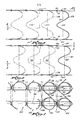
- Innerspring 20 includes a plurality of rows 24, 25, 26 of coils, all of the same twist, as, for example, all right handed twist or all left handed twist. As best illustrated in Figs. 1 and 3, each row 24, 25, and 26 of coils is formed from a continuous length of wire. The wire is wound to form a plurality of spaced coil pairs 27 interconnected by substantially Z-shaped wire segments 28, 18 disposed sequentially first in the plane of upper innerspring surface 21 and then within the plane of lower innerspring surface 23.
- each coil pair 27 comprises a first right handed coil 27a offset from a second right handed coil 27b, having the same number of turns as coil 27a.
- the axes of coils 27a lie within a plane 29 which is parallel to, but spaced apart from, a second plane 30 within which lie the axes of offset coils 27b. It will be appreciated that the axes of adjacent coils 27a and adjacent coils 27b are equidistant, the axes being generally perpendicular to the upper and lower surfaces 21 and 23 of innerspring unit 20.
- each of the coils 27a and 27b is illustrated as having approximately one and one half full turns or convolutions, this number is not critical. Thus, a greater or lesser number of convolutions may be used, depending upon the tensile strength of the wire and the manner in which the coils are formed so as to provide a spring force appropriate to the particular application.
- the coil interconnection technique utilized in innerspring mattress 20 prevents adjacent coils from binding when compressed even though they are not of hourglass configuration.
- a variety of shapes may be employed such as hourglass or potbellied, but the cylindrical shape illustrated is preferred.
- Each row 24, 25, and 26 is configured identical to each adjacent row and each coil within each row 24, 25, 26 is identical to every other coil and of the same twist or hand.
- the spacing between axes of adjacent coils within row 24 is the same as between axes spacing adjacent coils in rows 25 and 26.
- the adjacent coil pair in row 25 is interconnected in the same plane of upper innerspring - surface 21. This is best illustrated in Figs. 1, 3 and 4 where in row 24, typical adjacent coils 27a, 27b are interconnnected by Z-shaped wire segment 28 lying within upper innerspring surface 21.
- the adjacent coil pair 31 in row 25, coils 31a and 31b are interconnected by a Z-shaped wire segment 32 lying in the same plane of the upper innerspring surface 21 and Z-shaped wire segment 33 lying in the same plane of the lower surface 23.
- the Z-shaped segments which interconnect adjacent pairs of coils within each row are positioned so that they overlap the Z-shaped segments of the adjacent row of coils. These overlapped portions or sections of the Z-shaped segments are then tied together by helical wire connectors.
- a first set of helical wire connectors, herein designated 34 is disposed within the plane of upper innerspring surface '21 so as to join together overlapped portions 35 of upper Z-shaped interconnection segments 28, 32.
- a second set of helical wire connectors, herein designated 36 lie within the plane of lower innerspring surface 23 and serve to join together overlapped portions 37 of lower Z-shaped interconnection segments 18 and 33.
- the length of each helical wire is approximately the same as the length of the rows, and the helical wires 34, 36 extend parallel to the rows.
- the assembly of the helical wires to the row of continuous coils may be accomplished on an assembly machine.
- the adjacent rows of coils are positioned so that the sections 35 and 37 of the adjacent Z-shaped segments are positioned in overlapping relationship and a helical wire is then rotated or screwed onto the overlapping portions of the Z-shaped segments.
- the now-connected adjacent rows of coils may be indexed forwardly and another pair of upper and lower helical wires threaded over the next row of coils. This process is repeated for the desired length of the mattress, after which the spring assembly is removed from the machine.
- the diameters of the helical wires 34 and 36 are approximately onefourth the radius of the overlapped portions 35 and 37 of the Z-shaped segments. This relationship of having the radius of the Z-shaped segments over which the helical wire is threaded approximately eigth times the radius of the helical wire has the effect of permitting several rotations 38 of the helical wire to pass through and lock adjacent overlapped segments together. So locked or interconnected, the adjacent coils ; are free to pivot relative to each other but are locked against relative longitudinal or lateral movement. In other words, this relatively small diameter helical coil when used to lock the overlapped large radiused sections of the segments together, permits only relative pivotal movement between the adjacent interconnected coils.
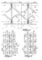
- each block 50 represents the outline of a typical upper Z-shaped interconnection segment 28 in coil row 24.
- each block 52 represents the outline of a typical upper Z-shaped interconnection segment 32 in coil row 25.
- Each block 51 represents the outline of typical lower Z-shaped interconnection segment 18 in coil row 24 and each block 53 represents the outline of a typical lower Z-shaped interconnection segment 33 in coil row 25.
- the blocks 50, 52, and'51, 53 represent load supporting units. Each of these units 50, 52, and 51, 53 are overlapped so that the effect of the construction of coil assembly is one of the very densely packed innerspring assembly with a very high count of coils.
- Figs. 1 and 5 it will be noted that the several rotations 38 of the helical wire 34 or 36 which pass around and lock adjacent overlapped segments 35 or 37 of the coils to coils of the adjacent rows are all centered in a common transverse plane 40. It will further be noted that this plane 40 passes through the vertical axes 41 of all of the coils contained in a transverse column of coils. Consequently, each coil is connected to two coils of the adjacent rows of coils by connectors 38 the centers 41 of which are located in a diametrical plane 42 of the coil.
- the spring assembly of Figs. 6-8 is identical to the spring assembly of Figs. 1-5, except that the rows of coils are positioned_within the interconnection Z-shaped segments so that the vertical axes of all of the coils of a single row are located in the same vertical plane 60, rather than being alternately staggered in two different planes as in the embodiment in Figs. 1-5.
- the Z-shaped segments, rather than extending outwardly from one side only of each coil extend outwardly beyond both sides of each coil so that this construction has the same advantages of the embodiment of Fig. 1-5 in that it minimizes or eliminates any tendency of the coils to overlap or contact adjacent convolutions of the same coil.
- each row of coils 124, 125, 126 is formed from a continuous length of wire and each wire is wound to form a plurality of spaced coil pairs 127 interconnected by substantially Z-shaped wire segments 128 disposed in the plane of upper innerspring surface 121.
- the substantially Z-shaped wire segments 118 interconnect adjacent coil pairs 127 within the plane of lower innerspring surface 123.
- each coil pair 127 comprises a first right handed coil 127a offset from a second right hand coil 127b having the same number of turns as coil 127a.
- the axes of coils 127a lie within the same plane 60 within which lie the axes of coils 127b.
- each row 124, 125, 126 is configured identically to each adjacent row and each coil within each row is of the same twist or hand. While the two embodiments of this invention have been illustrated as being of the same twist or hand throughout the spring unit, they could as well be of differing twist or of a mix of twists or rotational hands and still practice the invention of this application.
- the corners of the interconnecting Z-shaped segments are both located outwardly from the circumference of the coils 127a and 127b within each pair of coils in both the planes of the upper and lower surfaces of the mattress. This outward spacing of the Z-shaped segments facilitates interconnection of the overlapped portions of Z-shaped segments by the helical springs 134.
- the primary advantage of the continuous coil spring unit of this invention over the prior art continuous coil spring units is that is is so constructed that the coils 27 or 127 of either unit may be fully compressed without any lateral deflection or twist of the coils and without the coils taking any undesirable permanent set.
- the assembled spring units may be stacked and compressed for packaging much more densely than has theretofore been possible.
- the spring units of this invention may be made much less firm than has heretofore been required of continuous coil spring systems.
- the tendency for coils of a continuous coil spring unit to twist and - take a set if excessively compressed has dictated that the unit be made so firm that it could not be fully compressed in usage.
- this continuous coil spring unit may now be used in spring units or mattresses where softness, firmness or any varing degree of a firm feel is desired.
- the invention of this application because it eliminate the tendency of the coils of a continuous coil spring unit to become distorted and take a set when fully compressed, also enables these spring units to be placed in use without having to be heat treated and tempered after assembly.
Landscapes
- Mattresses And Other Support Structures For Chairs And Beds (AREA)
- Springs (AREA)
- Wire Processing (AREA)
Applications Claiming Priority (2)
| Application Number | Priority Date | Filing Date | Title |
|---|---|---|---|
| US212818 | 1980-12-04 | ||
| US06/212,818 US4358097A (en) | 1980-12-04 | 1980-12-04 | Spring assembly |
Publications (2)
| Publication Number | Publication Date |
|---|---|
| EP0053739A1 true EP0053739A1 (de) | 1982-06-16 |
| EP0053739B1 EP0053739B1 (de) | 1985-02-13 |
Family
ID=22792546
Family Applications (1)
| Application Number | Title | Priority Date | Filing Date |
|---|---|---|---|
| EP81109671A Expired EP0053739B1 (de) | 1980-12-04 | 1981-11-13 | Federgefüge |
Country Status (12)
| Country | Link |
|---|---|
| US (1) | US4358097A (de) |
| EP (1) | EP0053739B1 (de) |
| JP (1) | JPS5946167B2 (de) |
| AU (1) | AU547027B2 (de) |
| BR (1) | BR8107871A (de) |
| CA (1) | CA1156379A (de) |
| DE (1) | DE3168957D1 (de) |
| ES (1) | ES271793Y (de) |
| HK (1) | HK12690A (de) |
| MX (1) | MX163373B (de) |
| NZ (1) | NZ198909A (de) |
| PT (1) | PT74076A (de) |
Cited By (4)
| Publication number | Priority date | Publication date | Assignee | Title |
|---|---|---|---|---|
| EP0082259B1 (de) * | 1981-12-21 | 1986-08-27 | Leggett & Platt, Incorporated | Federeinlage aus in Längsrichtung miteinander verbundenen kontinuierlichen Schraubenfedern |
| WO1989006924A1 (en) * | 1988-02-02 | 1989-08-10 | Silentnight Holdings Plc | Box spring assemblies |
| GB2215199A (en) * | 1988-03-04 | 1989-09-20 | Airsprung Limited | Mattress |
| GB2339147A (en) * | 1999-03-30 | 2000-01-19 | Siddall And Hilton Springs Lim | Spring arrangement for mattresses |
Families Citing this family (18)
| Publication number | Priority date | Publication date | Assignee | Title |
|---|---|---|---|---|
| US4705079A (en) * | 1985-04-10 | 1987-11-10 | Leggett & Platt, Incorporated | Bedding coil spring unit and assembly method |
| US4625349A (en) * | 1985-04-10 | 1986-12-02 | Leggett & Platt, Incorporated | Bedding coil spring unit and assembly method |
| CA1254309A (en) * | 1985-09-25 | 1989-05-16 | Henry Zapletal | Offset continuous row coil spring assembly |
| US4726106A (en) * | 1986-09-10 | 1988-02-23 | Leggett & Platt, Incorporated | Method and apparatus for forming a row of spring coils from a continuous length of wire |
| US4766624A (en) * | 1986-10-17 | 1988-08-30 | Leggett & Platt, Incorporated | Mattress assembly having rows of coil springs formed from a single continuous length of wire |
| US4766625A (en) * | 1986-10-17 | 1988-08-30 | Leggett & Platt, Incorporated | Box spring having rows of coil springs formed from a single length of wire |
| US4790038A (en) * | 1987-08-05 | 1988-12-13 | Leggett & Platt, Incorporated | Bedding spring assembly |
| US4771495A (en) * | 1987-07-29 | 1988-09-20 | Leggett & Platt, Incorporated | Bedding spring mattress |
| US5127635A (en) * | 1990-05-14 | 1992-07-07 | Leggett & Platt, Incorporated | Pocketed continuous wire multiple coil spring bedding product |
| US6149143A (en) * | 1995-03-20 | 2000-11-21 | L&P Property Management Company | Spring structure for a mattress innerspring having coaxial coil units |
| RU2127994C1 (ru) * | 1995-03-20 | 1999-03-27 | Л. & П Проперти Менеджмент Компани | Внутренняя пружинная структура матраца с коаксиальными спиральными звеньями (варианты) и способ ее изготовления |
| US6173464B1 (en) | 1999-05-07 | 2001-01-16 | L&P Property Management Company | Pocketed bedding or seating product |
| EP1161165A1 (de) | 1999-02-05 | 2001-12-12 | L & P Property Management Company | Taschenfederanordnung für betten oder sitze |
| US6260223B1 (en) | 1999-12-15 | 2001-07-17 | Leggett & Platt, Incorporated | Pocketed coil spring units |
| US6375169B1 (en) | 2000-07-28 | 2002-04-23 | Hickory Springs Manufacturing Company | Mattress spring cushion assembly with combination of right-hand and left-hand spring units |
| DE102010015608A1 (de) | 2010-04-19 | 2011-10-20 | Ziaja Research Gmbh | Verfahren und Vorrichtung zur Bestimmung des Gesundheitszustandes eines Lebewesens |
| CN102494068A (zh) * | 2011-12-21 | 2012-06-13 | 广东中博汽车零部件有限公司 | 异型螺旋压缩弹簧及使用该弹簧的后盘式制动卡钳总成 |
| CN107028419B (zh) * | 2017-05-10 | 2023-06-27 | 广州市联柔机械设备有限公司 | 一种袋装弹簧串及袋装弹簧床芯 |
Citations (2)
| Publication number | Priority date | Publication date | Assignee | Title |
|---|---|---|---|---|
| GB263051A (en) * | 1926-07-07 | 1926-12-23 | John Teasdale Newborn | Improvements in and relating to spring mattresses and like resilient surfaces |
| US3911511A (en) * | 1974-11-29 | 1975-10-14 | Leggett & Platt | Spring assembly |
Family Cites Families (4)
| Publication number | Priority date | Publication date | Assignee | Title |
|---|---|---|---|---|
| US2114918A (en) * | 1936-06-15 | 1938-04-19 | Ernst F Engstrom | Spring |
| US2945245A (en) * | 1958-03-17 | 1960-07-19 | Nachman Corp | Coil spring assembly |
| US3489404A (en) * | 1967-10-24 | 1970-01-13 | Hickory Springs Mfg Co Inc | Spring assembly |
| GB1245033A (en) * | 1969-05-13 | 1971-09-02 | Slumberland Group Ltd | Spring interiors for mattresses, seats and the like |
-
1980
- 1980-12-04 US US06/212,818 patent/US4358097A/en not_active Expired - Lifetime
-
1981
- 1981-11-03 CA CA000389296A patent/CA1156379A/en not_active Expired
- 1981-11-09 NZ NZ198909A patent/NZ198909A/en unknown
- 1981-11-13 DE DE8181109671T patent/DE3168957D1/de not_active Expired
- 1981-11-13 EP EP81109671A patent/EP0053739B1/de not_active Expired
- 1981-11-20 AU AU77699/81A patent/AU547027B2/en not_active Expired
- 1981-11-27 MX MX190303A patent/MX163373B/es unknown
- 1981-12-03 BR BR8107871A patent/BR8107871A/pt unknown
- 1981-12-03 PT PT74076A patent/PT74076A/pt unknown
- 1981-12-03 JP JP56195096A patent/JPS5946167B2/ja not_active Expired
- 1981-12-04 ES ES1981271793U patent/ES271793Y/es not_active Expired
-
1990
- 1990-02-15 HK HK126/90A patent/HK12690A/en not_active IP Right Cessation
Patent Citations (2)
| Publication number | Priority date | Publication date | Assignee | Title |
|---|---|---|---|---|
| GB263051A (en) * | 1926-07-07 | 1926-12-23 | John Teasdale Newborn | Improvements in and relating to spring mattresses and like resilient surfaces |
| US3911511A (en) * | 1974-11-29 | 1975-10-14 | Leggett & Platt | Spring assembly |
Cited By (7)
| Publication number | Priority date | Publication date | Assignee | Title |
|---|---|---|---|---|
| EP0082259B1 (de) * | 1981-12-21 | 1986-08-27 | Leggett & Platt, Incorporated | Federeinlage aus in Längsrichtung miteinander verbundenen kontinuierlichen Schraubenfedern |
| WO1989006924A1 (en) * | 1988-02-02 | 1989-08-10 | Silentnight Holdings Plc | Box spring assemblies |
| GB2215199A (en) * | 1988-03-04 | 1989-09-20 | Airsprung Limited | Mattress |
| GB2215199B (en) * | 1988-03-04 | 1991-08-07 | Airsprung Limited | Mattress |
| GB2339147A (en) * | 1999-03-30 | 2000-01-19 | Siddall And Hilton Springs Lim | Spring arrangement for mattresses |
| GB2339147B (en) * | 1999-03-30 | 2000-06-07 | Siddall And Hilton Springs Lim | Improved spring arrangement for mattresses |
| US6339857B1 (en) | 1999-03-30 | 2002-01-22 | Siddall And Hilton Limited Of Central United Kingdom | Spring arrangement for mattresses |
Also Published As
| Publication number | Publication date |
|---|---|
| EP0053739B1 (de) | 1985-02-13 |
| PT74076A (en) | 1982-01-01 |
| AU547027B2 (en) | 1985-10-03 |
| DE3168957D1 (en) | 1985-03-28 |
| MX163373B (es) | 1992-05-04 |
| CA1156379A (en) | 1983-11-01 |
| HK12690A (en) | 1990-02-23 |
| ES271793U (es) | 1983-10-01 |
| BR8107871A (pt) | 1982-09-08 |
| ES271793Y (es) | 1984-04-01 |
| JPS57119710A (en) | 1982-07-26 |
| JPS5946167B2 (ja) | 1984-11-10 |
| US4358097A (en) | 1982-11-09 |
| NZ198909A (en) | 1985-07-12 |
| AU7769981A (en) | 1982-06-10 |
Similar Documents
| Publication | Publication Date | Title |
|---|---|---|
| US4358097A (en) | Spring assembly | |
| US4488712A (en) | Longitudinally laced continuous coil spring assembly | |
| US3911511A (en) | Spring assembly | |
| US5803440A (en) | Mattress innerspring structure having coaxial coil units | |
| US4960267A (en) | Edge-reinforced spring bedding product | |
| AU619643B2 (en) | Posturized spring bedding product | |
| US4790038A (en) | Bedding spring assembly | |
| US6149143A (en) | Spring structure for a mattress innerspring having coaxial coil units | |
| US4771495A (en) | Bedding spring mattress | |
| US4771494A (en) | Offset continuous row coil spring assembly | |
| US4905333A (en) | Spring bedding product | |
| US4369534A (en) | Center reinforced mattress | |
| ES2017050A6 (es) | Interior de muelles para colchones y similares. | |
| US3355747A (en) | Spring assembly | |
| US5669087A (en) | Lacing wire zoned mattress | |
| US2309164A (en) | Spring unit and method of constructing the same | |
| US5104099A (en) | Spring bedding product | |
| US20030025254A1 (en) | Spring assembly having bands of springs | |
| WO1988005640A1 (en) | Bedding spring assembly |
Legal Events
| Date | Code | Title | Description |
|---|---|---|---|
| PUAI | Public reference made under article 153(3) epc to a published international application that has entered the european phase |
Free format text: ORIGINAL CODE: 0009012 |
|
| AK | Designated contracting states |
Designated state(s): CH DE FR GB IT SE |
|
| 17P | Request for examination filed |
Effective date: 19820701 |
|
| ITF | It: translation for a ep patent filed | ||
| GRAA | (expected) grant |
Free format text: ORIGINAL CODE: 0009210 |
|
| AK | Designated contracting states |
Designated state(s): CH DE FR GB IT LI SE |
|
| REF | Corresponds to: |
Ref document number: 3168957 Country of ref document: DE Date of ref document: 19850328 |
|
| ET | Fr: translation filed | ||
| PLBE | No opposition filed within time limit |
Free format text: ORIGINAL CODE: 0009261 |
|
| STAA | Information on the status of an ep patent application or granted ep patent |
Free format text: STATUS: NO OPPOSITION FILED WITHIN TIME LIMIT |
|
| 26N | No opposition filed | ||
| PGFP | Annual fee paid to national office [announced via postgrant information from national office to epo] |
Ref country code: SE Payment date: 19891109 Year of fee payment: 9 |
|
| PGFP | Annual fee paid to national office [announced via postgrant information from national office to epo] |
Ref country code: CH Payment date: 19891117 Year of fee payment: 9 |
|
| PG25 | Lapsed in a contracting state [announced via postgrant information from national office to epo] |
Ref country code: SE Effective date: 19901114 |
|
| PG25 | Lapsed in a contracting state [announced via postgrant information from national office to epo] |
Ref country code: LI Effective date: 19901130 Ref country code: CH Effective date: 19901130 |
|
| REG | Reference to a national code |
Ref country code: CH Ref legal event code: PL |
|
| ITTA | It: last paid annual fee | ||
| EUG | Se: european patent has lapsed |
Ref document number: 81109671.8 Effective date: 19910705 |
|
| PGFP | Annual fee paid to national office [announced via postgrant information from national office to epo] |
Ref country code: GB Payment date: 20001004 Year of fee payment: 20 |
|
| PGFP | Annual fee paid to national office [announced via postgrant information from national office to epo] |
Ref country code: FR Payment date: 20001107 Year of fee payment: 20 |
|
| PGFP | Annual fee paid to national office [announced via postgrant information from national office to epo] |
Ref country code: DE Payment date: 20001124 Year of fee payment: 20 |
|
| PG25 | Lapsed in a contracting state [announced via postgrant information from national office to epo] |
Ref country code: GB Free format text: LAPSE BECAUSE OF EXPIRATION OF PROTECTION Effective date: 20011112 |
|
| REG | Reference to a national code |
Ref country code: GB Ref legal event code: PE20 Effective date: 20011112 |