EP0053855B1 - Rotor für eine Zentrifugalschleuderwaffe - Google Patents
Rotor für eine Zentrifugalschleuderwaffe Download PDFInfo
- Publication number
- EP0053855B1 EP0053855B1 EP81201300A EP81201300A EP0053855B1 EP 0053855 B1 EP0053855 B1 EP 0053855B1 EP 81201300 A EP81201300 A EP 81201300A EP 81201300 A EP81201300 A EP 81201300A EP 0053855 B1 EP0053855 B1 EP 0053855B1
- Authority
- EP
- European Patent Office
- Prior art keywords
- rotor
- barrel
- axis
- rotation
- projectile
- Prior art date
- Legal status (The legal status is an assumption and is not a legal conclusion. Google has not performed a legal analysis and makes no representation as to the accuracy of the status listed.)
- Expired
Links
- 230000005484 gravity Effects 0.000 claims description 3
- 230000002035 prolonged effect Effects 0.000 claims 1
- 229910000831 Steel Inorganic materials 0.000 description 1
- 230000002089 crippling effect Effects 0.000 description 1
- 230000007547 defect Effects 0.000 description 1
- 239000002360 explosive Substances 0.000 description 1
- 230000001681 protective effect Effects 0.000 description 1
- 239000010959 steel Substances 0.000 description 1
Images

Classifications
-
- F—MECHANICAL ENGINEERING; LIGHTING; HEATING; WEAPONS; BLASTING
- F41—WEAPONS
- F41B—WEAPONS FOR PROJECTING MISSILES WITHOUT USE OF EXPLOSIVE OR COMBUSTIBLE PROPELLANT CHARGE; WEAPONS NOT OTHERWISE PROVIDED FOR
- F41B3/00—Sling weapons
- F41B3/04—Centrifugal sling apparatus
Definitions
- the present invention relates to a rotor for a centrifugal launcher.
- centrifugal launcher in the context of the present a machine comprising a rotating part or rotor driven at high speed around an axis of rotation and equipped with means for successively bringing projectiles into the central area of the rotor to be substantially radially ejected from the latter by centrifugal force.
- Spherical projectiles nevertheless have considerable limitations in the military field: limitation of the speed of ejection; unfavorable ballistic qualities; practical impossibility of being provided with explosive charges, etc.
- a centrifugal rifle extending from a cylindrical annular chamber and tangentially to the latter.
- the assembly is mounted for rotation about the axis of said chamber.
- the latter and the axis of said barrel are therefore two left rights.
- Oblong projectiles, substantially in the form of a teardrop are successively ejected from a magazine in said annular chamber, a fixed stop being provided to prevent a projectile projected in said chamber from accompanying it in its rotation, this causing the projectile to enter said barrel.
- the object of the invention is to provide a rotor allowing the launch at very high speed, in good conditions, of oblong projectiles whose shape is extremely close to that of conventional shells (that is to say with tail, body and ogival head).
- a family of suitable projectiles in the context of the present invention is described in a joint application filed by the same Applicant (EP-A-53421).
- a rotor according to the invention of the type with a cylindrical barrel rotating around an axis, is characterized in that said barrel is clamped between two flanges mounted at the end of a drive shaft, these flanges having a free central space into which ends the end of the barrel closest to the axis of rotation.
- This internal end of the barrel is extended by a picking pallet extending as close to the axis of rotation of said rotor.
- the presentation device is not part of the invention. As an indication, reference can be made to request 82201489E from the same Applicant.
- cylindrical barrel is meant, in the context of the present, a tubular or semi-tubular barrel with a straight axis or substantially such.
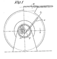
- the launcher shown comprises a rotor 1 constituted by two flanges 2 and 3 bolted to each other and enclosing a cylindrical barrel 4. This assembly is mounted and the end of a shaft 5 carried by bearings supported by a frame 6. This shaft 5 is capable of being driven by a motor, not shown.
- the flanges 2 and 3 are each provided with a central bore, which leaves a free space 7 in the center of the rotor. In this space is engaged the end of a supply and presentation device, shown diagrammatically at 8.
- the barrel 4 is arranged between the flanges 2 and 3 so that its axis X-X and the axis of rotation Y-Y of the rotor are two left straight lines.
- the projections of these straight lines in the plane of Figure 2 are also perpendicular to each other.
- the barrel 4 has a length such that its end closest to the YY axis ends in the escape 7. This end is provided with a picking pallet 9 which is in fact an extension of part of the wall of the .canon 4, of a width slightly less than the caliber of the projectiles 10. The length of said pallet is slightly greater than the distance separating the center of gravity of a projectile 10 from the tip of its warhead.
- the device 8 comprises a magazine 11 in which projectiles 10 are aligned side-by-side and pushed back towards a stop 12.
- a projectile applied against the stop 12 is immediately supported by the pallet 9 which, in its rotation, comes to pick up tangentially and remove it between the stop 10 and the supply of the next projectile.
- the rotor rotates clockwise and, in its rotation, the pallet 9 is placed between the axis of rotation YY and the projectile for pick the latter.
- the rotor is surrounded by two protective flanges 13 and 14 carrying a correction device 15 necessary to bring the axis of the projectile onto the trajectory of its center of gravity at the time of ejection.
- the barrel is a cylindrical steel tube, which is the preferred solution. It could however be replaced by a semi-cylindrical blading, without departing from the scope of the invention.
- a rotor according to the invention with a diameter of 950 cm, rotating at a speed of 12,443 rpm allows to communicate to a projectile an ejection speed of 800 m / s.
Landscapes
- Engineering & Computer Science (AREA)
- General Engineering & Computer Science (AREA)
- Centrifugal Separators (AREA)
- Toys (AREA)
- Radiation-Therapy Devices (AREA)
- Pinball Game Machines (AREA)
- Control Of Vending Devices And Auxiliary Devices For Vending Devices (AREA)
- Coating Apparatus (AREA)
- Manufacture Of Motors, Generators (AREA)
Claims (3)
Priority Applications (1)
| Application Number | Priority Date | Filing Date | Title |
|---|---|---|---|
| AT81201300T ATE8933T1 (de) | 1980-12-04 | 1981-11-24 | Rotor fuer eine zentrifugalschleuderwaffe. |
Applications Claiming Priority (2)
| Application Number | Priority Date | Filing Date | Title |
|---|---|---|---|
| BE2058887 | 1980-12-04 | ||
| BE2058887 | 1980-12-04 |
Publications (2)
| Publication Number | Publication Date |
|---|---|
| EP0053855A1 EP0053855A1 (de) | 1982-06-16 |
| EP0053855B1 true EP0053855B1 (de) | 1984-08-08 |
Family
ID=3865527
Family Applications (1)
| Application Number | Title | Priority Date | Filing Date |
|---|---|---|---|
| EP81201300A Expired EP0053855B1 (de) | 1980-12-04 | 1981-11-24 | Rotor für eine Zentrifugalschleuderwaffe |
Country Status (6)
| Country | Link |
|---|---|
| US (1) | US4632086A (de) |
| EP (1) | EP0053855B1 (de) |
| AT (1) | ATE8933T1 (de) |
| BE (1) | BE886482A (de) |
| DE (1) | DE3165448D1 (de) |
| IL (1) | IL64462A (de) |
Families Citing this family (15)
| Publication number | Priority date | Publication date | Assignee | Title |
|---|---|---|---|---|
| BE891864A (fr) * | 1982-01-22 | 1982-07-22 | Rutten Leon | Distributeur de projectiles pour lanceur centrifuge |
| IL109239A0 (en) * | 1993-04-08 | 1994-07-31 | Haneda Hisatsugu | Bullet shooting apparatus,bullet supply apparatus, and bullet shooting system comprising these apparatuses |
| US5699779A (en) * | 1995-08-25 | 1997-12-23 | Tidman; Derek A. | Method of and apparatus for moving a mass |
| US5857451A (en) * | 1995-11-15 | 1999-01-12 | Ciluffo; Gary | Launcher apparatus for spherical and disc-shaped objects |
| US6014964A (en) * | 1998-10-29 | 2000-01-18 | Advanced Launch Corporation | Method and apparatus for moving a mass in a spiral track |
| US6159112A (en) * | 1998-11-13 | 2000-12-12 | Creative Technology Applications, Inc. | Automatic throwing apparatus |
| US6520169B1 (en) * | 2000-02-29 | 2003-02-18 | Trinamic Technologies, Llc | Weapon for centrifugal propulsion of projectiles |
| US6712055B1 (en) * | 2001-03-07 | 2004-03-30 | Advanced Launch Corporation | Spiral mass launcher |
| US7032584B2 (en) * | 2001-03-07 | 2006-04-25 | Advanced Launch Corporation | Spiral mass launcher |
| US6668814B1 (en) | 2002-08-12 | 2003-12-30 | The United States Of America As Represented By The Secretary Of The Navy | Mechanism for deploying cylindrical objects from a spinning container |
| EP3414512A4 (de) * | 2016-02-14 | 2019-10-02 | Paul Westmeyer | Beschleunigungs- und präzisionsgesteuerter ausstoss von masse |
| AU2016100226B4 (en) * | 2016-02-18 | 2016-09-08 | Bhattacharya, Utpal DR | A projectile firing apparatus |
| US10059472B2 (en) * | 2016-04-19 | 2018-08-28 | SpinLaunch Inc. | Circular mass accelerator |
| CN111801543A (zh) * | 2018-02-20 | 2020-10-20 | 旋转发射公司 | 圆形质量加速器 |
| US12139276B2 (en) * | 2022-01-15 | 2024-11-12 | Space Kinetic Corp | System and method of energy and mass transfer in low-gravity environments |
Family Cites Families (15)
| Publication number | Priority date | Publication date | Assignee | Title |
|---|---|---|---|---|
| DE380697C (de) * | 1923-09-11 | Akt Ges Deutsche Maschf | Bergeversatzmaschine | |
| GB100791A (en) * | 1915-06-25 | 1900-01-01 | Schimmel Francois | An Improved Machine for Throwing Projectiles. |
| US1235897A (en) * | 1916-07-31 | 1917-08-07 | James F Howie | Centrifugal gun. |
| US1223069A (en) * | 1916-08-30 | 1917-04-17 | Edgar E Porter | Centrifugal gun. |
| US1357028A (en) * | 1917-10-17 | 1920-10-26 | William H Fulper | Centrifugal gun |
| US1332992A (en) * | 1918-06-20 | 1920-03-09 | Aero Tank Machine Gun Co Inc | Centrifugal machine-gun |
| US1408137A (en) * | 1918-10-16 | 1922-02-28 | Arthur C Bunnell | Centrifugal gun |
| US1783053A (en) * | 1929-01-28 | 1930-11-25 | Baden-Powell Baden Fletc Smyth | Centrifugal gun |
| GB437359A (en) * | 1934-01-26 | 1935-10-28 | Amerigo Mollica Landi | A device for launching projectiles by means of centrifugal force |
| FR796149A (fr) * | 1934-11-02 | 1936-03-30 | Perfectionnements aux fusils centrifuges | |
| US2043117A (en) * | 1934-11-02 | 1936-06-02 | Baden-Powell Baden Fletc Smyth | Centrifugal gun |
| US2391636A (en) * | 1944-03-20 | 1945-12-25 | Graham S Mcarthur | Gun |
| US2603203A (en) * | 1947-03-31 | 1952-07-15 | Herold Muriel | Variable angle target throwing apparatus |
| US3177862A (en) * | 1961-06-06 | 1965-04-13 | James G Allemann | Armament and fire control system for helicopters |
| US3613655A (en) * | 1969-06-30 | 1971-10-19 | Westinghouse Electric Corp | Centrifugal gun |
-
1980
- 1980-12-04 BE BE2/58887A patent/BE886482A/fr not_active IP Right Cessation
-
1981
- 1981-11-24 EP EP81201300A patent/EP0053855B1/de not_active Expired
- 1981-11-24 AT AT81201300T patent/ATE8933T1/de not_active IP Right Cessation
- 1981-11-24 DE DE8181201300T patent/DE3165448D1/de not_active Expired
- 1981-12-04 IL IL64462A patent/IL64462A/xx unknown
-
1983
- 1983-08-09 US US06/521,013 patent/US4632086A/en not_active Expired - Fee Related
Also Published As
| Publication number | Publication date |
|---|---|
| BE886482A (fr) | 1981-06-04 |
| EP0053855A1 (de) | 1982-06-16 |
| ATE8933T1 (de) | 1984-08-15 |
| DE3165448D1 (en) | 1984-09-13 |
| US4632086A (en) | 1986-12-30 |
| IL64462A (en) | 1988-07-31 |
Similar Documents
| Publication | Publication Date | Title |
|---|---|---|
| EP0053855B1 (de) | Rotor für eine Zentrifugalschleuderwaffe | |
| EP0346214B1 (de) | Verfahren und Vorrichtung zum Auswerfen von Submunition | |
| EP0293295B1 (de) | Durchdringendes Geschoss | |
| EP0905473B1 (de) | Grosskalibriges und weitreichendes Artilleriegeschoss | |
| EP0690283B1 (de) | Leitwerk für Geschosse, insbesondere für Überschallunterkalibergeschosse | |
| FR2599828A1 (fr) | Munition de petit ou moyen calibre a efficacite amelioree et portee limitee, en particulier pour la chasse | |
| FR2665950A1 (fr) | Munition d'une seule piece. | |
| EP0130893B1 (de) | Trägergeschoss für Streumunition | |
| EP0048644B1 (de) | Geschoss mit Leitflossen in Gestalt eines Pfeiles | |
| EP0457657B1 (de) | Durchdringendes Geschoss | |
| EP3994421B1 (de) | Teleskopmunition mit einem projektil mit einem stapel gerillter scheiben | |
| WO1994020813A1 (fr) | Munition de type telescopee | |
| EP2578987B1 (de) | Drallstabilisiertes Geschoss | |
| FR2552871A1 (fr) | Projectile antichar agissant en vitesse defilante | |
| EP0316216B1 (de) | Einrichtung zur Kreiselstabilisierung eines Geschoss-Steuerorgans | |
| FR2820817A1 (fr) | Projectile | |
| WO1991002211A1 (fr) | Perfectionnements apportes aux munitions destinees a etre tirees par une arme a canon lisse | |
| EP0767355B1 (de) | Unterkalibriges Flechette-Übungsgeschoss vom kinetischen Energietyp | |
| EP4008992A1 (de) | Kreiselstabilisiertes geschoss | |
| EP0053421B1 (de) | Geschoss für eine Zentrifugalschleuderwaffe | |
| EP4088082B1 (de) | Teleskopische munition mit einem durch eine ausfahrbare leitvorrichtung stabilisierten unterkalibrigen geschoss | |
| FR2601763A1 (fr) | Projectile sous-calibre de type fleche pour blindages actifs | |
| FR2666144A1 (fr) | Projectile sous-calibre avec cage de propulsion. | |
| FR2690240A1 (fr) | Projectile-flèche sous calibré. | |
| FR2629584A1 (fr) | Dispositif de stabilisation pour un projectile a faible moment d'inertie longitudinal tire a partir d'un tube raye |
Legal Events
| Date | Code | Title | Description |
|---|---|---|---|
| PUAI | Public reference made under article 153(3) epc to a published international application that has entered the european phase |
Free format text: ORIGINAL CODE: 0009012 |
|
| AK | Designated contracting states |
Designated state(s): AT CH DE FR GB IT LI LU NL SE |
|
| 17P | Request for examination filed |
Effective date: 19820506 |
|
| ITF | It: translation for a ep patent filed | ||
| GRAA | (expected) grant |
Free format text: ORIGINAL CODE: 0009210 |
|
| AK | Designated contracting states |
Designated state(s): AT CH DE FR GB IT LI LU NL SE |
|
| REF | Corresponds to: |
Ref document number: 8933 Country of ref document: AT Date of ref document: 19840815 Kind code of ref document: T |
|
| REF | Corresponds to: |
Ref document number: 3165448 Country of ref document: DE Date of ref document: 19840913 |
|
| PG25 | Lapsed in a contracting state [announced via postgrant information from national office to epo] |
Ref country code: LU Free format text: LAPSE BECAUSE OF NON-PAYMENT OF DUE FEES Effective date: 19841130 |
|
| PLBE | No opposition filed within time limit |
Free format text: ORIGINAL CODE: 0009261 |
|
| STAA | Information on the status of an ep patent application or granted ep patent |
Free format text: STATUS: NO OPPOSITION FILED WITHIN TIME LIMIT |
|
| 26N | No opposition filed | ||
| PGFP | Annual fee paid to national office [announced via postgrant information from national office to epo] |
Ref country code: DE Payment date: 19881227 Year of fee payment: 8 |
|
| PGFP | Annual fee paid to national office [announced via postgrant information from national office to epo] |
Ref country code: FR Payment date: 19891120 Year of fee payment: 9 |
|
| PGFP | Annual fee paid to national office [announced via postgrant information from national office to epo] |
Ref country code: SE Payment date: 19891121 Year of fee payment: 9 |
|
| PGFP | Annual fee paid to national office [announced via postgrant information from national office to epo] |
Ref country code: CH Payment date: 19891124 Year of fee payment: 9 |
|
| PGFP | Annual fee paid to national office [announced via postgrant information from national office to epo] |
Ref country code: AT Payment date: 19891127 Year of fee payment: 9 |
|
| ITTA | It: last paid annual fee | ||
| PGFP | Annual fee paid to national office [announced via postgrant information from national office to epo] |
Ref country code: NL Payment date: 19891130 Year of fee payment: 9 Ref country code: GB Payment date: 19891130 Year of fee payment: 9 |
|
| PGFP | Annual fee paid to national office [announced via postgrant information from national office to epo] |
Ref country code: LU Payment date: 19900608 Year of fee payment: 9 |
|
| PG25 | Lapsed in a contracting state [announced via postgrant information from national office to epo] |
Ref country code: DE Effective date: 19900801 |
|
| PG25 | Lapsed in a contracting state [announced via postgrant information from national office to epo] |
Ref country code: GB Effective date: 19901124 Ref country code: AT Effective date: 19901124 |
|
| PG25 | Lapsed in a contracting state [announced via postgrant information from national office to epo] |
Ref country code: SE Effective date: 19901125 |
|
| PG25 | Lapsed in a contracting state [announced via postgrant information from national office to epo] |
Ref country code: LI Effective date: 19901130 Ref country code: CH Effective date: 19901130 |
|
| PG25 | Lapsed in a contracting state [announced via postgrant information from national office to epo] |
Ref country code: NL Effective date: 19910601 |
|
| NLV4 | Nl: lapsed or anulled due to non-payment of the annual fee | ||
| GBPC | Gb: european patent ceased through non-payment of renewal fee | ||
| PG25 | Lapsed in a contracting state [announced via postgrant information from national office to epo] |
Ref country code: FR Effective date: 19910731 |
|
| REG | Reference to a national code |
Ref country code: CH Ref legal event code: PL |
|
| REG | Reference to a national code |
Ref country code: CH Ref legal event code: AUV Free format text: LE BREVET CI-DESSUS EST TOMBE EN DECHEANCE FAUTE DE PAIEMENT, DE LA 10E ANNUITE. |
|
| REG | Reference to a national code |
Ref country code: FR Ref legal event code: ST |
|
| EUG | Se: european patent has lapsed |
Ref document number: 81201300.1 Effective date: 19910705 |