EP0053867A1 - Emetteur thermique d'électrons et sa fabrication - Google Patents
Emetteur thermique d'électrons et sa fabrication Download PDFInfo
- Publication number
- EP0053867A1 EP0053867A1 EP81300963A EP81300963A EP0053867A1 EP 0053867 A1 EP0053867 A1 EP 0053867A1 EP 81300963 A EP81300963 A EP 81300963A EP 81300963 A EP81300963 A EP 81300963A EP 0053867 A1 EP0053867 A1 EP 0053867A1
- Authority
- EP
- European Patent Office
- Prior art keywords
- alloy
- activator
- emitter
- substrate
- layer
- Prior art date
- Legal status (The legal status is an assumption and is not a legal conclusion. Google has not performed a legal analysis and makes no representation as to the accuracy of the status listed.)
- Granted
Links
- 238000000034 method Methods 0.000 title claims abstract description 22
- 229910045601 alloy Inorganic materials 0.000 claims abstract description 48
- 239000000956 alloy Substances 0.000 claims abstract description 48
- 239000011159 matrix material Substances 0.000 claims abstract description 29
- 239000012190 activator Substances 0.000 claims abstract description 25
- SYQBFIAQOQZEGI-UHFFFAOYSA-N osmium atom Chemical compound [Os] SYQBFIAQOQZEGI-UHFFFAOYSA-N 0.000 claims abstract description 25
- WFKWXMTUELFFGS-UHFFFAOYSA-N tungsten Chemical compound [W] WFKWXMTUELFFGS-UHFFFAOYSA-N 0.000 claims abstract description 22
- 229910052721 tungsten Inorganic materials 0.000 claims abstract description 20
- 239000010937 tungsten Substances 0.000 claims abstract description 20
- RZJQYRCNDBMIAG-UHFFFAOYSA-N [Cu].[Cu].[Cu].[Cu].[Cu].[Cu].[Cu].[Cu].[Cu].[Cu].[Cu].[Cu].[Cu].[Cu].[Cu].[Cu].[Cu].[Cu].[Zn].[Ag].[Ag].[Ag].[Ag].[Ag].[Ag].[Ag].[Ag].[Ag].[Ag].[Ag].[Ag].[Ag].[Ag].[Ag].[Ag].[Ag].[Ag].[Ag].[Ag].[Ag].[Ag].[Ag].[Ag].[Ag].[Ag].[Ag].[Ag].[Ag].[Ag].[Ag].[Ag].[Ag].[Ag].[Ag].[Ag].[Ag].[Ag].[Ag].[Ag].[Ag].[Ag].[Ag].[Ag].[Ag].[Ag].[Ag].[Ag].[Ag].[Ag].[Ag].[Ag].[Ag].[Ag].[Ag].[Ag].[Ag].[Ag].[Ag].[Ag].[Ag].[Ag].[Sn].[Sn].[Sn].[Sn].[Sn].[Sn].[Sn].[Sn].[Sn].[Sn].[Sn].[Sn].[Sn].[Sn].[Sn].[Sn].[Sn].[Sn] Chemical class [Cu].[Cu].[Cu].[Cu].[Cu].[Cu].[Cu].[Cu].[Cu].[Cu].[Cu].[Cu].[Cu].[Cu].[Cu].[Cu].[Cu].[Cu].[Zn].[Ag].[Ag].[Ag].[Ag].[Ag].[Ag].[Ag].[Ag].[Ag].[Ag].[Ag].[Ag].[Ag].[Ag].[Ag].[Ag].[Ag].[Ag].[Ag].[Ag].[Ag].[Ag].[Ag].[Ag].[Ag].[Ag].[Ag].[Ag].[Ag].[Ag].[Ag].[Ag].[Ag].[Ag].[Ag].[Ag].[Ag].[Ag].[Ag].[Ag].[Ag].[Ag].[Ag].[Ag].[Ag].[Ag].[Ag].[Ag].[Ag].[Ag].[Ag].[Ag].[Ag].[Ag].[Ag].[Ag].[Ag].[Ag].[Ag].[Ag].[Ag].[Ag].[Sn].[Sn].[Sn].[Sn].[Sn].[Sn].[Sn].[Sn].[Sn].[Sn].[Sn].[Sn].[Sn].[Sn].[Sn].[Sn].[Sn].[Sn] RZJQYRCNDBMIAG-UHFFFAOYSA-N 0.000 claims abstract description 17
- 229910052762 osmium Inorganic materials 0.000 claims description 23
- ZOKXTWBITQBERF-UHFFFAOYSA-N Molybdenum Chemical compound [Mo] ZOKXTWBITQBERF-UHFFFAOYSA-N 0.000 claims description 22
- 239000011733 molybdenum Substances 0.000 claims description 21
- 239000010410 layer Substances 0.000 claims description 17
- 229910052750 molybdenum Inorganic materials 0.000 claims description 16
- 239000000758 substrate Substances 0.000 claims description 16
- 239000000470 constituent Substances 0.000 claims description 10
- 239000000203 mixture Substances 0.000 claims description 8
- 238000004519 manufacturing process Methods 0.000 claims description 7
- 150000001875 compounds Chemical class 0.000 claims description 6
- 239000000843 powder Substances 0.000 claims description 6
- 239000002344 surface layer Substances 0.000 claims description 6
- 238000004544 sputter deposition Methods 0.000 claims description 5
- 229910052702 rhenium Inorganic materials 0.000 claims description 4
- WUAPFZMCVAUBPE-UHFFFAOYSA-N rhenium atom Chemical compound [Re] WUAPFZMCVAUBPE-UHFFFAOYSA-N 0.000 claims description 4
- 238000005275 alloying Methods 0.000 claims description 3
- 229910002056 binary alloy Inorganic materials 0.000 claims description 3
- 238000005551 mechanical alloying Methods 0.000 claims description 3
- 238000000151 deposition Methods 0.000 claims description 2
- 230000008021 deposition Effects 0.000 claims description 2
- 238000000975 co-precipitation Methods 0.000 claims 1
- 239000011248 coating agent Substances 0.000 abstract description 10
- 238000000576 coating method Methods 0.000 abstract description 10
- 229910001182 Mo alloy Inorganic materials 0.000 abstract description 6
- 229910000820 Os alloy Inorganic materials 0.000 abstract description 6
- QVQLCTNNEUAWMS-UHFFFAOYSA-N barium oxide Chemical compound [Ba]=O QVQLCTNNEUAWMS-UHFFFAOYSA-N 0.000 description 36
- PNEYBMLMFCGWSK-UHFFFAOYSA-N Alumina Chemical compound [O-2].[O-2].[O-2].[Al+3].[Al+3] PNEYBMLMFCGWSK-UHFFFAOYSA-N 0.000 description 17
- 229910052741 iridium Inorganic materials 0.000 description 8
- GKOZUEZYRPOHIO-UHFFFAOYSA-N iridium atom Chemical compound [Ir] GKOZUEZYRPOHIO-UHFFFAOYSA-N 0.000 description 8
- 239000010955 niobium Substances 0.000 description 8
- 229910052751 metal Inorganic materials 0.000 description 7
- 239000002184 metal Substances 0.000 description 7
- 229910052788 barium Inorganic materials 0.000 description 6
- DSAJWYNOEDNPEQ-UHFFFAOYSA-N barium atom Chemical compound [Ba] DSAJWYNOEDNPEQ-UHFFFAOYSA-N 0.000 description 6
- BRPQOXSCLDDYGP-UHFFFAOYSA-N calcium oxide Chemical compound [O-2].[Ca+2] BRPQOXSCLDDYGP-UHFFFAOYSA-N 0.000 description 6
- ODINCKMPIJJUCX-UHFFFAOYSA-N calcium oxide Inorganic materials [Ca]=O ODINCKMPIJJUCX-UHFFFAOYSA-N 0.000 description 6
- 239000000292 calcium oxide Substances 0.000 description 6
- 239000013078 crystal Substances 0.000 description 6
- FYYHWMGAXLPEAU-UHFFFAOYSA-N Magnesium Chemical compound [Mg] FYYHWMGAXLPEAU-UHFFFAOYSA-N 0.000 description 5
- 229910052749 magnesium Inorganic materials 0.000 description 5
- 239000011777 magnesium Substances 0.000 description 5
- 229910052712 strontium Inorganic materials 0.000 description 5
- CIOAGBVUUVVLOB-UHFFFAOYSA-N strontium atom Chemical compound [Sr] CIOAGBVUUVVLOB-UHFFFAOYSA-N 0.000 description 5
- UFHFLCQGNIYNRP-UHFFFAOYSA-N Hydrogen Chemical compound [H][H] UFHFLCQGNIYNRP-UHFFFAOYSA-N 0.000 description 4
- 239000001257 hydrogen Substances 0.000 description 4
- 229910052739 hydrogen Inorganic materials 0.000 description 4
- 150000002739 metals Chemical class 0.000 description 4
- GUCVJGMIXFAOAE-UHFFFAOYSA-N niobium atom Chemical compound [Nb] GUCVJGMIXFAOAE-UHFFFAOYSA-N 0.000 description 4
- OYPRJOBELJOOCE-UHFFFAOYSA-N Calcium Chemical compound [Ca] OYPRJOBELJOOCE-UHFFFAOYSA-N 0.000 description 3
- KJTLSVCANCCWHF-UHFFFAOYSA-N Ruthenium Chemical compound [Ru] KJTLSVCANCCWHF-UHFFFAOYSA-N 0.000 description 3
- 229910052784 alkaline earth metal Inorganic materials 0.000 description 3
- 150000001342 alkaline earth metals Chemical class 0.000 description 3
- 150000004645 aluminates Chemical class 0.000 description 3
- 229910052791 calcium Inorganic materials 0.000 description 3
- 239000011575 calcium Substances 0.000 description 3
- 239000000945 filler Substances 0.000 description 3
- 238000003825 pressing Methods 0.000 description 3
- 229910052707 ruthenium Inorganic materials 0.000 description 3
- 238000005245 sintering Methods 0.000 description 3
- 229910052810 boron oxide Inorganic materials 0.000 description 2
- 150000004649 carbonic acid derivatives Chemical class 0.000 description 2
- RKTYLMNFRDHKIL-UHFFFAOYSA-N copper;5,10,15,20-tetraphenylporphyrin-22,24-diide Chemical group [Cu+2].C1=CC(C(=C2C=CC([N-]2)=C(C=2C=CC=CC=2)C=2C=CC(N=2)=C(C=2C=CC=CC=2)C2=CC=C3[N-]2)C=2C=CC=CC=2)=NC1=C3C1=CC=CC=C1 RKTYLMNFRDHKIL-UHFFFAOYSA-N 0.000 description 2
- JKWMSGQKBLHBQQ-UHFFFAOYSA-N diboron trioxide Chemical compound O=BOB=O JKWMSGQKBLHBQQ-UHFFFAOYSA-N 0.000 description 2
- 229910052758 niobium Inorganic materials 0.000 description 2
- 239000002245 particle Substances 0.000 description 2
- 239000003870 refractory metal Substances 0.000 description 2
- 238000001179 sorption measurement Methods 0.000 description 2
- 229910002058 ternary alloy Inorganic materials 0.000 description 2
- FQNGWRSKYZLJDK-UHFFFAOYSA-N [Ca].[Ba] Chemical compound [Ca].[Ba] FQNGWRSKYZLJDK-UHFFFAOYSA-N 0.000 description 1
- 125000004429 atom Chemical group 0.000 description 1
- 238000000498 ball milling Methods 0.000 description 1
- 230000015572 biosynthetic process Effects 0.000 description 1
- 238000010586 diagram Methods 0.000 description 1
- 229910003460 diamond Inorganic materials 0.000 description 1
- 239000010432 diamond Substances 0.000 description 1
- 238000009826 distribution Methods 0.000 description 1
- 230000000694 effects Effects 0.000 description 1
- 238000010894 electron beam technology Methods 0.000 description 1
- 238000001704 evaporation Methods 0.000 description 1
- 238000010304 firing Methods 0.000 description 1
- 238000010438 heat treatment Methods 0.000 description 1
- 238000005470 impregnation Methods 0.000 description 1
- 239000000463 material Substances 0.000 description 1
- 238000012986 modification Methods 0.000 description 1
- 230000004048 modification Effects 0.000 description 1
- 230000003647 oxidation Effects 0.000 description 1
- 238000007254 oxidation reaction Methods 0.000 description 1
- 125000004430 oxygen atom Chemical group O* 0.000 description 1
- 239000004033 plastic Substances 0.000 description 1
- 229920003023 plastic Polymers 0.000 description 1
- 238000005498 polishing Methods 0.000 description 1
- 239000012255 powdered metal Substances 0.000 description 1
- 239000000700 radioactive tracer Substances 0.000 description 1
- 239000011819 refractory material Substances 0.000 description 1
- 229910052703 rhodium Inorganic materials 0.000 description 1
- 239000010948 rhodium Substances 0.000 description 1
- MHOVAHRLVXNVSD-UHFFFAOYSA-N rhodium atom Chemical compound [Rh] MHOVAHRLVXNVSD-UHFFFAOYSA-N 0.000 description 1
- 239000000126 substance Substances 0.000 description 1
- 229910002066 substitutional alloy Inorganic materials 0.000 description 1
- UDKYUQZDRMRDOR-UHFFFAOYSA-N tungsten Chemical compound [W][W][W][W][W][W][W][W][W][W][W][W][W][W][W][W][W][W][W][W][W][W][W][W][W][W][W][W][W][W][W][W][W][W][W][W][W][W][W][W][W][W][W][W][W][W][W][W] UDKYUQZDRMRDOR-UHFFFAOYSA-N 0.000 description 1
Images

Classifications
-
- H—ELECTRICITY
- H01—ELECTRIC ELEMENTS
- H01J—ELECTRIC DISCHARGE TUBES OR DISCHARGE LAMPS
- H01J1/00—Details of electrodes, of magnetic control means, of screens, or of the mounting or spacing thereof, common to two or more basic types of discharge tubes or lamps
- H01J1/02—Main electrodes
- H01J1/13—Solid thermionic cathodes
- H01J1/14—Solid thermionic cathodes characterised by the material
Definitions
- the present invention relates to thermionic electron emitters and methods of making them.
- a thermionic cathode known as the 'M' type is disclosed in U.S. Patent 3,373,307.
- This cathode is a dispenser cathode which comprises a refractory metal matrix of tungsten (W) or tungsten and molybdenum in reactive relationship with an alkaline earth activator which supplies free barium oxide to the emitting surface of the matrix.
- W tungsten
- molybdenum in reactive relationship with an alkaline earth activator which supplies free barium oxide to the emitting surface of the matrix.
- a thin porous coating of a refractory metal having a work function higher than that of tungsten covers the emitting surface.
- the preferred metal is osmium (0s) although it could be iridium, ruthenium or rhenium or simple substitutional alloys of them.
- U.S. Patent 4,165,473 discloses a different type of cathode herein referred to as 'mixed-matrix' type.
- a preferred example of it comprises particles of pure iridium mixed in fixed proportions with particles of pure tungsten, and impregnated with activator.
- the iridium and tungsten form an alloy 'but it is believed that optimum results require the alloying to be incomplete'.
- the emission of such a cathode is comparable with that of the 'M' type.
- the optimum proportions are 20% iridium and 80% tungsten.
- the iridium may be replaced by osmium, ruthenium or a mixture thereof, and the tunsten may be replaced by molybdenum.
- the replacements of iridium are in the same proportion as the iridium.
- the European Application having publication number 0019992 discloses various cathodes, a preferred example having a tungsten or molybdenum substrate impregnated with activator and an emissive surface comprising a thin coating of 20% osmium fully alloyed with 80% tungsten.
- Alternatives for the osmium such as iridium, ruthenium, rhenium or rhodium are disclosed. The proportions of the replacements are stated to be the same as for osmium.
- the application suggests a theory explaining the operation of the disclosed cathodes.
- Ba0 barium oxide
- Os osmium Os
- the theory postulates that Ba0 reacts with Os to form 'Osmate' type componds and that by controlling the chemical potential of the osmium, the optimum compound for emission is produced.
- a thermionic electron emitter comprising: at least an emissive surface layer predominantly of an atomically rough (as hereinafter defined) alloy, taken from the group of alloys comprising: and an alkaline earth activator.
- a method of making a thermionic electron emitter in which: an atomically rough (as hereinafter defined) alloy of the group comprising: and an alkaline earth activator are brought together so that the activator activates the alloy, and the alloy forms at least a predominant part of an emissive surface layer of the emitter.
- ⁇ phase alloys are used.
- the constituents of the ⁇ phase alloys are as follows:
- Nb Niobium
- Cb Cold-doped
- atomically rough we mean that in one layer of the atomic structure of the alloy the atoms have a spacing which is large compared to the spacing between that layer and its adjacent parallel layer.
- binary alloys as listed above are used.
- ternary alloys comprising the listed pairs of elements together with a third element with which any one of the pair also forms an atomically rough alloy could be used.
- a porous substrate of refractory material such as tungsten and/or molybdenum may be impregnated with activator, and then the alloy is formed on the substrate by co-sputtering or by vapour deposition, of the constituents of the alloy onto the substrate.
- the alloy may, in some cases, be formed by co-precipitating the constituents on the substrate from chemically reducible compounds of the constituents.
- a mixture of the powdered constituents of the ⁇ phase alloys in the requisite proportions fort phase is pressed and sintered in known manner to give a porous matrix, furnaced at a temperature and for a time required to ensure full alloying and then impregnated with the activator.
- a powder of fully alloyed ⁇ phase alloy may be pressed and sintered to produce a porous matrix and then impregnated with activator.
- the ⁇ phase alloy powder or constituents may be placed on a layer of tungsten and/or molybdenum powder before pressing and sintering to form the matrix.
- the alkaline earth activator preferably comprises barium oxide, calcium oxide and aluminium oxide in conventional proportions.
- barium oxide instead of calcium oxide, another oxide of an alkaline earth metal other than barium may be used, and instead of aluminium oxides there may be used boron oxide.
- the metal other than barium may be strontium or magnesium or a mixture of any two or more of calcium, strontium and magnesium.
- carbonates of calcium, strontium and/or magnesium may be used instead of the oxides.
- the barium oxide orients into dipoles with barium uppermost and consequently produces a lower work function surface.
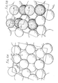
- the ⁇ phase alloy has an open tetragonal structure with a number of hexagonal or pentagonal depressions per unit cell depending on the crystal face exposed providing interstitial sorption sites for the barium oxide.
- it has an open structure into which the barium oxide dipoles fit surrounded by regions where barium oxide would have a low heat of sorption. This controls the spacing of the dipoles thus controlling the coverage of the surface. It is believed that the coverage of the surface of the alloy with the barium oxide film responsible for the low work function is substantially less than the coverage of a pure osmium surface.
- the dipoles should be evenly spaced over the whole surface, being spaced sufficiently to reduce depolarisation effects.
- the cathode comprises a molybdenum tube 1 containing in a lower cavity a heater 2, and in an upper cavity a thermionic emitter 3.
- the emitter 3 comprises a porous matrix 4 of tungsten impregnated with an activator in the form of a mixture of barium oxide, aluminium oxide, and calcium oxide in the molecular proportions 3:1:1 ⁇ 2 respectively, and a coating 5 on the free surface of the matrix.
- the coating 5 comprises a fully alloyed ⁇ phase alloy of osmium and molybdenum having the proportions of about 46 to 56 wt% osmium and 54 to 44 wt% molybdenum.
- the coating in this example is formed by co-sputtering osmium and molybdenum in the desired proportions onto the impregnated matrix.
- the coating is preferably about 1 ⁇ m thick in this example, but it may have a thickness in the range 2000 ⁇ to 2 ⁇ m.
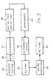
- an illustrative method of making the emitter of Figure 1 is as follows, referring to Figure 3.
- a porous matrix of tungsten is impregnated with filler e.g. a plastics material to enable it to be machined (30) and then the filler is at least partially removed by firing in air (31).
- the button is then subjected to wet hydrogen at a temperature of 1000° to remove (by oxidation) remnants of the filler followed by dry hydrogen at 1800 0 C to produce reducing conditions (32).
- the matrix is then impregnated with activator, e.g. barium calcium aluminate (33), cleaned ultrasonically (34) and fired in a hydrogen atmosphere at a temperature of e.g. 1000°C for e.g. 2 to 5 minutes (35).
- a layer of osmium and molybdenum in the proportions to form the phase alloy layer of about 46 to 56 wt% osmium and 54 to 44 wt% molybdenum, corresponding to layer 5 of Figure 2 is then co-sputtered onto the matrix (36). Finally the matrix with the layer is fired in hydrogen at 1300°C to form the V phase alloy (37).
- the button is polished with a final polish using 1 ⁇ 4 ⁇ m diamond paste to give a smooth surface before the alloy is sputtered onto the polished surface. In practice, the polishing step (38) would take place on the machined button before it is deplasticised
- the coating may be formed by co-evaporating the metals osmium and molybdenium onto the matrix 4. This is done by directing electron beams onto targets of osmium and molybdenum to cause the metals to evaporate from the targets onto the matrix in the correct proportion.
- the coating could also be formed by co-precipitating the metals onto the matrix from reducible compounds thereof.
- the whole emitter 3 comprises a V phase alloy of osmium and molybdenum in the approximate proportions 46 to 56 wt% osmium and 54 to 44 wt% molybdenum, impregnated with an alkaline earth aluminate activator.
- the emitter of Figure 2 is made for example by:
- An alternative method of making the emitter of Figure 2 comprises:
- Another alternative method of making the emitter of Figure 2 is to use energetic mechanical alloying techniques as described in British Patents 1298944 and 1265343 (Inco) to form the ⁇ phase alloy, followed by forming a porous matrix and impregnation with activator.
- the impregnant may have the form described hereinbefore but in other proportions such as 4:1:1 or 5:2:3.
- another oxide of an alkaline earth metal other than barium may be used, and instead of aluminium oxide there may be used boron oxide.
- the metal other than barium may be strontium or magnesium or a mixture of any two or more of calcium, strontium and magnesium.
- oxides of the alkaline earth metal other than barium compounds which decompose on heating to oxides e.g. carbonates of those metals may be used.
- the ⁇ phase alloy has an open tetragonal structure and the free surface of the alloy layer comprises principally molybdenum.
- the ⁇ phase alloy has an atomically rough surface (as hereinbefore defined).
- the ⁇ phase structure provides interstitial sites 50 (Figure 4A) into which the oxygen atoms of the barium oxide fit ( Figure 4B). Thus the coverage of the surface by the barium oxide is controlled.
- ⁇ phase molybdenum/osmium alloy examples of the invention have been described with reference to ⁇ phase molybdenum/osmium alloy, other ⁇ phase alloys which are stable at cathode operating temperatures may be used.
- ⁇ phase alloys are:
- Nb Niobium
- Cb Coldium
- Cathodes incorporating such alloys may be made in the ways described above by way of example.
- alloys other than ⁇ phase may be used.
- these other alloys have a feature in common with ⁇ phase, that is they are atomically rough alloys as hereinbefore defined.
- Tphase ternary alloys comprising the listed pairs of elements alloyed together with a third element which forms a ⁇ phase alloy which is stable at cathode operating temperatures with one of the pair of elements may be used.
Landscapes
- Solid Thermionic Cathode (AREA)
Applications Claiming Priority (2)
| Application Number | Priority Date | Filing Date | Title |
|---|---|---|---|
| GB8039472 | 1980-12-09 | ||
| GB8039472 | 1980-12-09 |
Publications (2)
| Publication Number | Publication Date |
|---|---|
| EP0053867A1 true EP0053867A1 (fr) | 1982-06-16 |
| EP0053867B1 EP0053867B1 (fr) | 1985-05-08 |
Family
ID=10517870
Family Applications (1)
| Application Number | Title | Priority Date | Filing Date |
|---|---|---|---|
| EP81300963A Expired EP0053867B1 (fr) | 1980-12-09 | 1981-03-09 | Emetteur thermique d'électrons et sa fabrication |
Country Status (3)
| Country | Link |
|---|---|
| US (1) | US4417173A (fr) |
| EP (1) | EP0053867B1 (fr) |
| DE (1) | DE3170370D1 (fr) |
Cited By (3)
| Publication number | Priority date | Publication date | Assignee | Title |
|---|---|---|---|---|
| GB2173943A (en) * | 1985-04-18 | 1986-10-22 | Noblelight Limited | Improvements in and relating to cathodes |
| NL9201450A (nl) * | 1991-10-24 | 1993-05-17 | Samsung Electronic Devices | Werkwijze voor het vervaardigen van een geimpregneerde kathodestruktuur. |
| GB2268325A (en) * | 1992-07-01 | 1994-01-05 | Thorn Emi Electronics Ltd | Thermionic cathode structure. |
Families Citing this family (12)
| Publication number | Priority date | Publication date | Assignee | Title |
|---|---|---|---|---|
| US4675570A (en) * | 1984-04-02 | 1987-06-23 | Varian Associates, Inc. | Tungsten-iridium impregnated cathode |
| EP0248417B1 (fr) * | 1986-06-06 | 1992-11-11 | Kabushiki Kaisha Toshiba | Cathode imprégnée |
| US4823044A (en) * | 1988-02-10 | 1989-04-18 | Ceradyne, Inc. | Dispenser cathode and method of manufacture therefor |
| US5418070A (en) * | 1988-04-28 | 1995-05-23 | Varian Associates, Inc. | Tri-layer impregnated cathode |
| US5218263A (en) * | 1990-09-06 | 1993-06-08 | Ceradyne, Inc. | High thermal efficiency dispenser-cathode and method of manufacture therefor |
| US5156705A (en) * | 1990-09-10 | 1992-10-20 | Motorola, Inc. | Non-homogeneous multi-elemental electron emitter |
| DE4114856A1 (de) * | 1991-05-07 | 1992-11-12 | Licentia Gmbh | Vorratskathode und verfahren zu deren herstellung |
| KR930008611B1 (ko) * | 1991-06-13 | 1993-09-10 | 삼성전관 주식회사 | 함침형 음극구조체와 그 제조방법 |
| DE4408941A1 (de) * | 1994-03-16 | 1995-09-21 | Licentia Gmbh | Vorratskathode |
| KR100338035B1 (ko) * | 1994-12-28 | 2002-11-23 | 삼성에스디아이 주식회사 | 직열형음극및그제조방법 |
| US6100621A (en) * | 1998-03-26 | 2000-08-08 | The United States Of America As Represented By The United States Department Of Energy | Thermionic converter with differentially heated cesium-oxygen source and method of operation |
| WO2005068685A1 (fr) * | 2004-01-15 | 2005-07-28 | Ebara Corporation | Revetement en alliage pour barriere de diffusion, procede d'elaboration, et element de dispositif haute temperature |
Citations (6)
| Publication number | Priority date | Publication date | Assignee | Title |
|---|---|---|---|---|
| US3373307A (en) * | 1963-11-21 | 1968-03-12 | Philips Corp | Dispenser cathode |
| GB1265343A (fr) * | 1968-03-01 | 1972-03-01 | ||
| US3676731A (en) * | 1970-03-05 | 1972-07-11 | Siemens Ag | Dispenser cathode structure |
| GB1298944A (en) * | 1969-08-26 | 1972-12-06 | Int Nickel Ltd | Powder-metallurgical products and the production thereof |
| GB2012474A (en) * | 1977-12-26 | 1979-07-25 | Hitachi Ltd | Thermionic emission cathodes |
| US4165473A (en) * | 1976-06-21 | 1979-08-21 | Varian Associates, Inc. | Electron tube with dispenser cathode |
Family Cites Families (2)
| Publication number | Priority date | Publication date | Assignee | Title |
|---|---|---|---|---|
| US2509702A (en) * | 1947-01-14 | 1950-05-30 | Eureka Television And Tube Cor | Cathode for thermionic valves |
| BE533455A (fr) * | 1953-11-18 |
-
1981
- 1981-03-06 US US06/241,037 patent/US4417173A/en not_active Expired - Fee Related
- 1981-03-09 DE DE8181300963T patent/DE3170370D1/de not_active Expired
- 1981-03-09 EP EP81300963A patent/EP0053867B1/fr not_active Expired
Patent Citations (6)
| Publication number | Priority date | Publication date | Assignee | Title |
|---|---|---|---|---|
| US3373307A (en) * | 1963-11-21 | 1968-03-12 | Philips Corp | Dispenser cathode |
| GB1265343A (fr) * | 1968-03-01 | 1972-03-01 | ||
| GB1298944A (en) * | 1969-08-26 | 1972-12-06 | Int Nickel Ltd | Powder-metallurgical products and the production thereof |
| US3676731A (en) * | 1970-03-05 | 1972-07-11 | Siemens Ag | Dispenser cathode structure |
| US4165473A (en) * | 1976-06-21 | 1979-08-21 | Varian Associates, Inc. | Electron tube with dispenser cathode |
| GB2012474A (en) * | 1977-12-26 | 1979-07-25 | Hitachi Ltd | Thermionic emission cathodes |
Cited By (4)
| Publication number | Priority date | Publication date | Assignee | Title |
|---|---|---|---|---|
| GB2173943A (en) * | 1985-04-18 | 1986-10-22 | Noblelight Limited | Improvements in and relating to cathodes |
| NL9201450A (nl) * | 1991-10-24 | 1993-05-17 | Samsung Electronic Devices | Werkwijze voor het vervaardigen van een geimpregneerde kathodestruktuur. |
| GB2268325A (en) * | 1992-07-01 | 1994-01-05 | Thorn Emi Electronics Ltd | Thermionic cathode structure. |
| GB2268325B (en) * | 1992-07-01 | 1996-01-03 | Thorn Emi Electronics Ltd | Thermionic cathode structure |
Also Published As
| Publication number | Publication date |
|---|---|
| US4417173A (en) | 1983-11-22 |
| DE3170370D1 (en) | 1985-06-13 |
| EP0053867B1 (fr) | 1985-05-08 |
Similar Documents
| Publication | Publication Date | Title |
|---|---|---|
| EP0053867B1 (fr) | Emetteur thermique d'électrons et sa fabrication | |
| EP0091161B1 (fr) | Procédé de fabrication d'une cathode à réserve et cathode à réserve fabriquée selon ce procédé | |
| US4518890A (en) | Impregnated cathode | |
| EP0179513B1 (fr) | Procédé de fabrication d'une cathode à réserve comprenant du scandate et cathode à réserve fabriquée par ce procédé | |
| US4570099A (en) | Thermionic electron emitters | |
| US3155864A (en) | Dispenser cathode | |
| KR900009071B1 (ko) | 함침형 음극 | |
| US4675570A (en) | Tungsten-iridium impregnated cathode | |
| US2996795A (en) | Thermionic cathodes and methods of making | |
| US3558966A (en) | Directly heated dispenser cathode | |
| US4109058A (en) | X-ray tube anode with alloyed surface and method of making the same | |
| US4626470A (en) | Impregnated cathode | |
| US3437865A (en) | Thermionic electron emitter having a porous refractory metal matrix and an alloy of active metal and mobilizer metal therein | |
| CA1101479A (fr) | Traduction non-disponible | |
| EP0156454B1 (fr) | Source d'électrons à émission thermo-ionique | |
| US5418070A (en) | Tri-layer impregnated cathode | |
| EP0157634B1 (fr) | Cathode à réserve contenant du tungstène et de l'iridium | |
| US5266414A (en) | Solid solution matrix cathode | |
| Haas | Thermionic electron sources | |
| US5747921A (en) | Impregnation type cathode for a cathodic ray tube | |
| Tuck | The use of platinum metals in modern thermionic emitters | |
| JPH06203738A (ja) | 電子管用カソード | |
| JP2585232B2 (ja) | 含浸形陰極 | |
| JPS6134218B2 (fr) | ||
| JP2650638B2 (ja) | 陰極線管 |
Legal Events
| Date | Code | Title | Description |
|---|---|---|---|
| PUAI | Public reference made under article 153(3) epc to a published international application that has entered the european phase |
Free format text: ORIGINAL CODE: 0009012 |
|
| AK | Designated contracting states |
Designated state(s): CH DE FR GB IT NL SE |
|
| 17P | Request for examination filed |
Effective date: 19820816 |
|
| ITF | It: translation for a ep patent filed | ||
| GRAA | (expected) grant |
Free format text: ORIGINAL CODE: 0009210 |
|
| AK | Designated contracting states |
Designated state(s): CH DE FR GB IT LI NL SE |
|
| REF | Corresponds to: |
Ref document number: 3170370 Country of ref document: DE Date of ref document: 19850613 |
|
| ET | Fr: translation filed | ||
| PG25 | Lapsed in a contracting state [announced via postgrant information from national office to epo] |
Ref country code: DE Effective date: 19851202 |
|
| PG25 | Lapsed in a contracting state [announced via postgrant information from national office to epo] |
Ref country code: SE Effective date: 19860310 |
|
| PLBE | No opposition filed within time limit |
Free format text: ORIGINAL CODE: 0009261 |
|
| STAA | Information on the status of an ep patent application or granted ep patent |
Free format text: STATUS: NO OPPOSITION FILED WITHIN TIME LIMIT |
|
| PG25 | Lapsed in a contracting state [announced via postgrant information from national office to epo] |
Ref country code: LI Effective date: 19860331 Ref country code: CH Effective date: 19860331 |
|
| 26N | No opposition filed | ||
| PG25 | Lapsed in a contracting state [announced via postgrant information from national office to epo] |
Ref country code: NL Effective date: 19861001 |
|
| GBPC | Gb: european patent ceased through non-payment of renewal fee | ||
| PG25 | Lapsed in a contracting state [announced via postgrant information from national office to epo] |
Ref country code: FR Free format text: LAPSE BECAUSE OF NON-PAYMENT OF DUE FEES Effective date: 19861128 |
|
| REG | Reference to a national code |
Ref country code: CH Ref legal event code: PL |
|
| NLV4 | Nl: lapsed or anulled due to non-payment of the annual fee | ||
| REG | Reference to a national code |
Ref country code: FR Ref legal event code: ST |
|
| PG25 | Lapsed in a contracting state [announced via postgrant information from national office to epo] |
Ref country code: GB Effective date: 19881118 |
|
| EUG | Se: european patent has lapsed |
Ref document number: 81300963.6 Effective date: 19870224 |