EP0053870A1 - Kompaktes Relais - Google Patents
Kompaktes Relais Download PDFInfo
- Publication number
- EP0053870A1 EP0053870A1 EP81303143A EP81303143A EP0053870A1 EP 0053870 A1 EP0053870 A1 EP 0053870A1 EP 81303143 A EP81303143 A EP 81303143A EP 81303143 A EP81303143 A EP 81303143A EP 0053870 A1 EP0053870 A1 EP 0053870A1
- Authority
- EP
- European Patent Office
- Prior art keywords
- base member
- adhesive
- relay
- compact design
- base
- Prior art date
- Legal status (The legal status is an assumption and is not a legal conclusion. Google has not performed a legal analysis and makes no representation as to the accuracy of the status listed.)
- Granted
Links
- 239000000853 adhesive Substances 0.000 claims abstract description 39
- 230000001070 adhesive effect Effects 0.000 claims abstract description 39
- 230000000087 stabilizing effect Effects 0.000 claims 1
- 238000010276 construction Methods 0.000 description 5
- 239000011347 resin Substances 0.000 description 4
- 229920005989 resin Polymers 0.000 description 4
- 238000007789 sealing Methods 0.000 description 4
- 239000007789 gas Substances 0.000 description 3
- 238000007669 thermal treatment Methods 0.000 description 3
- 238000009423 ventilation Methods 0.000 description 2
- 230000015572 biosynthetic process Effects 0.000 description 1
- 230000017525 heat dissipation Effects 0.000 description 1
- 239000000463 material Substances 0.000 description 1
- 238000000465 moulding Methods 0.000 description 1
Images

Classifications
-
- H—ELECTRICITY
- H01—ELECTRIC ELEMENTS
- H01H—ELECTRIC SWITCHES; RELAYS; SELECTORS; EMERGENCY PROTECTIVE DEVICES
- H01H50/00—Details of electromagnetic relays
- H01H50/02—Bases; Casings; Covers
- H01H50/023—Details concerning sealing, e.g. sealing casing with resin
Definitions
- This invention relates to miniature or compact design relays and, more particulaly, to compact design relays having a sealed construction.
- a compact design relay of this type is manufactured by covering a base member provided with necessary terminal pins with a case open at the bottom and a resin adhesive which is applied to portions of the base in engagement with the open end of the cover and those receiving the terminal pins and then thermally hardened.
- a resin adhesive which is applied to portions of the base in engagement with the open end of the cover and those receiving the terminal pins and then thermally hardened.
- An object of the invention is to remove the drawbacks discussed above.
- a compact design relay in which a gap between a base member provided with terminal pins and a case coverinq the base is sealed by fillinq the qap with an adhesive and thermally hardening the adhesive, and in which a vent hole is formed in a portion of the case and/or the base free from the adhesive and is sealed with a further adhesive after the thermal treatment of the first-mentioned adhesive.
- This compact design relay is manufactured by covering a base member 2 provided with terminal pins 1 with a case 3 open at the bottom and sealing the assembly with a resin adhesive 4 which is applied to portions of the base in engagement with the open end of the cover and those receiving the terminal pins and then thermally hardened.
- the adhesive 4 may extend over the while area of the lower end opening of the case 4 and this construction has the drawbacks as discussed previously.
- FIGs. 2 and 3 show a preferred embodiment in which the invention is applied to such a compact design relay as disclosed in the United States Patent No. 4,227,162 assigned to the same assignee of this invention.
- a base 2 has a portion 6 which expands outwardly downwardly and extends along the longitudinal center axis of the base 2.
- a small hol 5 is formed in a recess 7 provided at a given portion of the expanded base portion 6 and a plurality of terminal pins 1 are arranged parallelly along the opposite sides of the expanded portion 6.
- the inflated air due to the inner pressure produced when thermally hardening the adhesive 4 filing the gap between the case 3 and base 2 and also gases produced from the adhesive at this time may be exhausted through the hole 5 to the outside, so that there is no possibility of the formation of small air passages in the hardened adhesive and also a cloud of gases produced from the adhesive.
- the small hole 5 is sealed with a small quantity of adhesive 8 in the last step.
- a very small quantity of adhesive 8 is required for sealing the small hole 5, so that there is no possibility of increasing the internal pressure, and the reliability of sealing can be increased.
- the molding can be provided over a reduced area, and the quantity of the necessary resin can be reduced.
- improved ventilation can be obtained since a gap is formed between the portion of the relay base at which the terminal pins are mounted the surface portion of the printed-circuit board.
- the expanded portion 6 is provided on the underside of the base, the small hole 5 for sealing can be provided in the expanded portion 6 without sacrifice in appearance in use at all. Further, if the interior of the expanded portion 6 of the base 2 is utilized for accommodating a relay coil section, the height of the relay from the printed-circuit board in the mounted state can be reduced to obtain a more compact construction as a whole.
- a recess 7 is formed so that adhesive may spread over the portion of the recess 7 around the small hole 5, it is only necessary for the adhesive to close the small hole 5 which is very small, and it is not necessary to fill the entire recess 7 with the adhesive.
- the small hole 5 is provided at the center of the expanded portion 6 of the base 2 in the longitudinal direction thereof, this position of the small hole 5 is by no means limitative.
- a ridge 9 provided on the expanded portion 6 to surround the small hall 5 may prevent the adhesive 8 from spreading widely over the surface of the expanded portion 6 in case an excessive quantity of adhesive is applied to the hole 5.
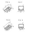
- the base 2 is provided with the expanded portion 6, it is also possible to make the lower surface of the base 2 flat, as shown in Figs. 6 and 7, with grooves 11 formed in the terminal pin mounting portions of the base 2 so that the terminal pins 1 are mounted in these grooves 11 and the grooves 11 are filled with the adhesive 4, provided that there is no problem in ventilation of the underside of the relay.
- the small hole 5 may be provided in any suitable portion other than the qrooves.
- the ridge 9 surrounding the small hole 5 and the ridge 10 for the purpose of steadiness may be provided also in this embodiment in the same manner as in the embodiment of Figs. 4 and 5. However, such a single bar-like ridge 12 may be substituted for the surrounding ridge 10, as shown in Fiq. 6.
- Figs. 8 and 9 may be utilized.
- no grooves are not provided in the base 2 and the adhesive 4 is applied to whole the bottom surface.s of the base 2 except for the areas surrounded by the ridge 9 surrounding the small hole 5 and the ridge 10 for the purpose of steadiness.
- the adhesive is unavoidably increased in its quantity. However, the increase in the quantity of adhesive may be considerably reduced by widening the areas surrounded by the ridges 9 and 10.
- the small hole 5 may be provided in the case 3 or to penetrate both the case 3 and base 2. From the standpoint of appearance, howevere, it is of course better to provide the small hole 5 in the underside of the base 2.
Landscapes
- Physics & Mathematics (AREA)
- Electromagnetism (AREA)
- Switch Cases, Indication, And Locking (AREA)
Applications Claiming Priority (2)
| Application Number | Priority Date | Filing Date | Title |
|---|---|---|---|
| JP175421/80U | 1980-12-05 | ||
| JP1980175421U JPS5797347U (de) | 1980-12-05 | 1980-12-05 |
Publications (2)
| Publication Number | Publication Date |
|---|---|
| EP0053870A1 true EP0053870A1 (de) | 1982-06-16 |
| EP0053870B1 EP0053870B1 (de) | 1985-10-02 |
Family
ID=15995796
Family Applications (1)
| Application Number | Title | Priority Date | Filing Date |
|---|---|---|---|
| EP81303143A Expired EP0053870B1 (de) | 1980-12-05 | 1981-07-09 | Kompaktes Relais |
Country Status (3)
| Country | Link |
|---|---|
| EP (1) | EP0053870B1 (de) |
| JP (1) | JPS5797347U (de) |
| DE (1) | DE3172517D1 (de) |
Cited By (6)
| Publication number | Priority date | Publication date | Assignee | Title |
|---|---|---|---|---|
| GB2120853A (en) * | 1982-05-24 | 1983-12-07 | Illinois Tool Works | Liquid contaminant resistant electric switches |
| EP0110098A1 (de) * | 1982-10-22 | 1984-06-13 | International Standard Electric Corporation | Elektromagnetisches Relais |
| EP0118841A3 (en) * | 1983-03-12 | 1985-01-23 | International Standard Electric Corporation | Method of sealing a relay |
| US4580005A (en) * | 1983-07-02 | 1986-04-01 | International Standard Electric Corporation | Wash-tight electromagnetic relay |
| EP0351547A3 (de) * | 1988-07-20 | 1990-12-19 | Trw Inc. | Abgedichtete Relaisanordnung |
| EP0713233A3 (de) * | 1994-10-24 | 1998-03-04 | Siemens Aktiengesellschaft | Anordnung eines Relais mit einem Steckadapter und Verfahren zur Herstellung dieser Anordnung |
Citations (3)
| Publication number | Priority date | Publication date | Assignee | Title |
|---|---|---|---|---|
| DE2618492A1 (de) * | 1976-04-27 | 1977-11-10 | Siemens Ag | Schutzvorrichtung fuer ein elektromechanisches bauelement |
| DE2908887A1 (de) * | 1978-03-08 | 1979-09-13 | Idec Izumi Corp | Elektromagnetisches relais |
| GB2029107A (en) * | 1978-08-17 | 1980-03-12 | Bosch Gmbh Robert | Electro-magnetic relay |
Family Cites Families (1)
| Publication number | Priority date | Publication date | Assignee | Title |
|---|---|---|---|---|
| JPS6030049A (ja) * | 1983-07-28 | 1985-02-15 | Seiko Electronic Components Ltd | リチウムシ−ト打抜型 |
-
1980
- 1980-12-05 JP JP1980175421U patent/JPS5797347U/ja active Pending
-
1981
- 1981-07-09 DE DE8181303143T patent/DE3172517D1/de not_active Expired
- 1981-07-09 EP EP81303143A patent/EP0053870B1/de not_active Expired
Patent Citations (4)
| Publication number | Priority date | Publication date | Assignee | Title |
|---|---|---|---|---|
| DE2618492A1 (de) * | 1976-04-27 | 1977-11-10 | Siemens Ag | Schutzvorrichtung fuer ein elektromechanisches bauelement |
| DE2908887A1 (de) * | 1978-03-08 | 1979-09-13 | Idec Izumi Corp | Elektromagnetisches relais |
| US4227162A (en) * | 1978-03-08 | 1980-10-07 | Izumi Denki Corporation | Electromagnet relay with specific housing structure |
| GB2029107A (en) * | 1978-08-17 | 1980-03-12 | Bosch Gmbh Robert | Electro-magnetic relay |
Cited By (8)
| Publication number | Priority date | Publication date | Assignee | Title |
|---|---|---|---|---|
| GB2120853A (en) * | 1982-05-24 | 1983-12-07 | Illinois Tool Works | Liquid contaminant resistant electric switches |
| EP0110098A1 (de) * | 1982-10-22 | 1984-06-13 | International Standard Electric Corporation | Elektromagnetisches Relais |
| EP0118841A3 (en) * | 1983-03-12 | 1985-01-23 | International Standard Electric Corporation | Method of sealing a relay |
| US4580005A (en) * | 1983-07-02 | 1986-04-01 | International Standard Electric Corporation | Wash-tight electromagnetic relay |
| EP0130500A3 (de) * | 1983-07-02 | 1986-10-08 | Alcatel N.V. | Waschdichtes elektromagnetisches Relais |
| AU568369B2 (en) * | 1983-07-02 | 1987-12-24 | Alcatel N.V. | Relay in sealed housing |
| EP0351547A3 (de) * | 1988-07-20 | 1990-12-19 | Trw Inc. | Abgedichtete Relaisanordnung |
| EP0713233A3 (de) * | 1994-10-24 | 1998-03-04 | Siemens Aktiengesellschaft | Anordnung eines Relais mit einem Steckadapter und Verfahren zur Herstellung dieser Anordnung |
Also Published As
| Publication number | Publication date |
|---|---|
| DE3172517D1 (en) | 1985-11-07 |
| EP0053870B1 (de) | 1985-10-02 |
| JPS5797347U (de) | 1982-06-15 |
Similar Documents
| Publication | Publication Date | Title |
|---|---|---|
| KR100253452B1 (ko) | 자동차용 전환 및 제어장치 | |
| US20200137904A1 (en) | Circuit device, method for manufacturing circuit device and connector | |
| US4913285A (en) | Water-and-dust-proof push-button switch housing dummy terminal for air venting | |
| JPS59132522A (ja) | 電気スイツチ | |
| EP0053870A1 (de) | Kompaktes Relais | |
| US5752856A (en) | Sealed fuse connector | |
| JP6499604B2 (ja) | 電子制御装置 | |
| US4599596A (en) | Chip type fuse | |
| JP2005150621A (ja) | 半導体装置 | |
| US4277663A (en) | Electrical switch | |
| US6056576A (en) | ZIF socket with top loading contacts | |
| JP2017175069A (ja) | 電子制御装置 | |
| US5395256A (en) | Contact element for SMD printed circuit boards and mounting method | |
| KR102109955B1 (ko) | 전자 제어 장치 | |
| KR970003325A (ko) | 회로 차단기 | |
| JP2815443B2 (ja) | 電気工学的ユニット、特にリレーのためのケーシング | |
| JP3463310B2 (ja) | 表面実装リレー | |
| CN117356003A (zh) | 机动车用控制装置 | |
| JP6715196B2 (ja) | 電子制御装置 | |
| JPH0716370U (ja) | 気密端子 | |
| JP2001152906A (ja) | 内燃機関用制御ユニット | |
| JPH0441545Y2 (de) | ||
| JP4257832B2 (ja) | スイッチ装置 | |
| JPS6032800Y2 (ja) | 電気部品の封入構造 | |
| JPS6244523Y2 (de) |
Legal Events
| Date | Code | Title | Description |
|---|---|---|---|
| PUAI | Public reference made under article 153(3) epc to a published international application that has entered the european phase |
Free format text: ORIGINAL CODE: 0009012 |
|
| AK | Designated contracting states |
Designated state(s): DE FR GB IT |
|
| 17P | Request for examination filed |
Effective date: 19821109 |
|
| ITF | It: translation for a ep patent filed | ||
| GRAA | (expected) grant |
Free format text: ORIGINAL CODE: 0009210 |
|
| AK | Designated contracting states |
Designated state(s): DE FR GB IT |
|
| REF | Corresponds to: |
Ref document number: 3172517 Country of ref document: DE Date of ref document: 19851107 |
|
| ET | Fr: translation filed | ||
| PLBE | No opposition filed within time limit |
Free format text: ORIGINAL CODE: 0009261 |
|
| STAA | Information on the status of an ep patent application or granted ep patent |
Free format text: STATUS: NO OPPOSITION FILED WITHIN TIME LIMIT |
|
| 26N | No opposition filed | ||
| ITTA | It: last paid annual fee | ||
| PGFP | Annual fee paid to national office [announced via postgrant information from national office to epo] |
Ref country code: FR Payment date: 19930512 Year of fee payment: 13 |
|
| PGFP | Annual fee paid to national office [announced via postgrant information from national office to epo] |
Ref country code: GB Payment date: 19930702 Year of fee payment: 13 |
|
| PGFP | Annual fee paid to national office [announced via postgrant information from national office to epo] |
Ref country code: DE Payment date: 19930929 Year of fee payment: 13 |
|
| PG25 | Lapsed in a contracting state [announced via postgrant information from national office to epo] |
Ref country code: GB Effective date: 19940709 |
|
| GBPC | Gb: european patent ceased through non-payment of renewal fee |
Effective date: 19940709 |
|
| PG25 | Lapsed in a contracting state [announced via postgrant information from national office to epo] |
Ref country code: FR Effective date: 19950331 |
|
| PG25 | Lapsed in a contracting state [announced via postgrant information from national office to epo] |
Ref country code: DE Effective date: 19950401 |
|
| REG | Reference to a national code |
Ref country code: FR Ref legal event code: ST |