EP0053870B1 - Kompaktes Relais - Google Patents
Kompaktes Relais Download PDFInfo
- Publication number
- EP0053870B1 EP0053870B1 EP81303143A EP81303143A EP0053870B1 EP 0053870 B1 EP0053870 B1 EP 0053870B1 EP 81303143 A EP81303143 A EP 81303143A EP 81303143 A EP81303143 A EP 81303143A EP 0053870 B1 EP0053870 B1 EP 0053870B1
- Authority
- EP
- European Patent Office
- Prior art keywords
- adhesive
- trough
- relay
- shaped portion
- vent hole
- Prior art date
- Legal status (The legal status is an assumption and is not a legal conclusion. Google has not performed a legal analysis and makes no representation as to the accuracy of the status listed.)
- Expired
Links
Images
Classifications
-
- H—ELECTRICITY
- H01—ELECTRIC ELEMENTS
- H01H—ELECTRIC SWITCHES; RELAYS; SELECTORS; EMERGENCY PROTECTIVE DEVICES
- H01H50/00—Details of electromagnetic relays
- H01H50/02—Bases; Casings; Covers
- H01H50/023—Details concerning sealing, e.g. sealing casing with resin
Definitions
- This invention relates to miniature or compact design relays and, more particularly, to compact design relays having a sealed construction.
- a compact design relay of this type is manufactured by covering a base member provided with necessary terminal pins with a case open at the bottom, and a resin adhesive is applied to portions of the base in engagement with the open end of the cover and those receiving the terminal pins and then thermally hardened.
- a resin adhesive is applied to portions of the base in engagement with the open end of the cover and those receiving the terminal pins and then thermally hardened.
- An object of the invention is to remove the drawbacks discussed above.
- German Specification DE-A-2,618,492 there is disclosed a base member provided with a relay mechanism and terminal pins connected to said relay mechanism; a case member covering said base member; a first adhesive applied to gaps formed between said base member and said case member and between said base member and said terminal pins, said first adhesive being thermally hardened so as to seal said gaps in an air-tight manner; an air vent hole formed in the base member; a second adhesive which has been applied to said air vent hole after the said first adhesive has been hardened.
- the base member is substantially flat and the air vent hole is not disposed outwardly of the first adhesive.
- the present invention is therefore characterised in that said base member, as known per se, has a centrally disposed trough-shaped portion and first and second flat portions on opposite sides of said trough-shaped portion, said terminal pins being mounted in said flat portions, and further characterised in that the bottom of the trough-shaped portion projects substantially outwardly both of the first adhesive and of the first and second flat portions, the air vent hole being formed in the bottom of the trough-shaped portion so as to be free from said first adhesive.
- the construction of the present invention ensures that the first adhesive can be introduced in such a way that the gaps between the flat portions of the base member and the case member, and the gaps between the flat portions and the terminal pins, can be easily sealed in a single manufacturing process with a minimum of first adhesive and without any risk that the first adhesive will enter the air vent hole.
- the construction of the present invention also ensures that there is a substantial gap between the portion of the relay base at which the terminal pins are mounted and the surface portion of the printed circuit board so as to ensure adequate ventilation.
- a relay having a centrally disposed trough-shaped portion is disclosed per se in the Applicants' German Specification DE-A-2,908,887.
- the relay of the latter specification does not have an air vent hole sealed by a second adhesive.
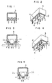
- FIG. 1 For the better understanding of the invention, an example of a conventional compact design relay, which is shown in Figure 1 will first be described.
- This compact design relay is manufactured by covering a base member 2 provided with terminal pins 1 with a case 3 which is open at the bottom, and sealing the assembly with a resin adhesive 4 which is applied to portions of the base in engagement with the open end of the cover and those receiving the terminal pins, the resin then being thermally hardened.
- the adhesive 4 may extend over the whole area of the lower end opening of the case 4 and this construction has the drawbacks as discussed previously.
- Figures 2 and 3 show a preferred embodiment in which the invention is applied to a compact design relay such as disclosed in German Specification DE-A-2 908 887 assigned to the same assignee of this invention.
- a base 2 has a projecting trough-shaped portion 6 which projects outwardly downwardly and extends along the longitudinal centre axis of the base 2.
- the base 2 has first and second flat portions 2a, 2b on opposite sides of the projecting trough-shaped portions 6.
- the bottom of the projecting trough-shaped portion 6 thus projects substantially outwardly of the adhesive 4 and of the flat portions 1a, 2b.
- a small vent hole 5 is formed in a recess 7 provided in the bottom of the projecting trough-shaped portion 6 so that the vent hole 5 is free from the adhesive 4.
- a plurality of terminal pins 1 are arranged parallel to each other along the opposite sides of the projecting portion 6, the terminal pins 1 being mounted in the flat portions 2a, 2b.
- the inflated air due to the inner pressure produced when thermally hardening the adhesive 4 filling the gap between the case 3 and base 2 and also gases produced from the adhesive at this time may be exhausted through the hole 5 to the outside, so that there is no possibility of either the formation of small air passages in the hardened adhesive or of a cloud of gases produced from the adhesive.
- the small vent hole 5 is sealed with a small quantity of adhesive 8 as the last step. At this time, only a very small quantity of adhesive 8 is required for sealing the small vent hole 5, so that there is no possibility of increasing the internal pressure, and the reliability of sealing can be increased.
- the moulding can be provided over a reduced area, and the quantity of the necessary resin can be reduced. Further, when the relay is mounted on a printed circuit board P for use thereon, improved ventilation can be obtained since a gap is formed between the portion of the relay base at which the terminal pins are mounted on the surface portion of the printed-circuit board. Further, since the projection trough-shaped portion 6 is provided on the underside of the base, the small vent hole 5 for sealing is provided in the bottom of the projecting trough-shaped portion 6 without any sacrifice in appearance in use at all. Further, if the interior of the projecting trough-shaped portion 6 of the base 2 is utilized for accommodating a relay coil section, the height of the relay from the printed-circuit board in the mounted state can be reduced to obtain a more compact construction as a whole.
- a recess 7 is formed so that adhesive may spread over the portion of the recess 7 around the small vent hole 5, it is only necessary for the adhesive to close the vent hole 5 which is very small, and it is not necessary to fill the entire recess 7 with the adhesive.
- the small vent hole 5 is provided at the centre of the bottom of the projecting trough-shaped portion 6 of the base 2 in the longitudinal direction thereof, this position of the small vent hole 5 is by no means limitative.
- a ridge 9 which is provided on the bottom of the projecting trough-shaped portion 6 to surround the small vent hole 5 may prevent the adhesive 8 from spreading widely over the surface of the bottom of the projecting trough-shaped portion 6 in case an excessive quantity of adhesive is applied to the vent hole 5.
Landscapes
- Physics & Mathematics (AREA)
- Electromagnetism (AREA)
- Switch Cases, Indication, And Locking (AREA)
Claims (5)
Applications Claiming Priority (2)
| Application Number | Priority Date | Filing Date | Title |
|---|---|---|---|
| JP175421/80U | 1980-12-05 | ||
| JP1980175421U JPS5797347U (de) | 1980-12-05 | 1980-12-05 |
Publications (2)
| Publication Number | Publication Date |
|---|---|
| EP0053870A1 EP0053870A1 (de) | 1982-06-16 |
| EP0053870B1 true EP0053870B1 (de) | 1985-10-02 |
Family
ID=15995796
Family Applications (1)
| Application Number | Title | Priority Date | Filing Date |
|---|---|---|---|
| EP81303143A Expired EP0053870B1 (de) | 1980-12-05 | 1981-07-09 | Kompaktes Relais |
Country Status (3)
| Country | Link |
|---|---|
| EP (1) | EP0053870B1 (de) |
| JP (1) | JPS5797347U (de) |
| DE (1) | DE3172517D1 (de) |
Families Citing this family (6)
| Publication number | Priority date | Publication date | Assignee | Title |
|---|---|---|---|---|
| JPS58214231A (ja) * | 1982-05-24 | 1983-12-13 | イリノイ・ツ−ル・ワ−クス・インコ−ポレイテツド | 耐液電気スイツチ |
| DE3239047C2 (de) * | 1982-10-22 | 1986-01-16 | Standard Elektrik Lorenz Ag, 7000 Stuttgart | Elektromagnetisches Relais |
| DE3308791C2 (de) * | 1983-03-12 | 1986-08-21 | Standard Elektrik Lorenz Ag, 7000 Stuttgart | Verfahren zur Herstellung eines dichten elektromagnetischen Relais |
| DE3323922A1 (de) * | 1983-07-02 | 1985-01-03 | Standard Elektrik Lorenz Ag, 7000 Stuttgart | Waschdichtes elektromagnetisches relais |
| US4975545A (en) * | 1988-07-20 | 1990-12-04 | Wickes Manufacturing Company | Sealed relay assembly |
| DE4437954C1 (de) * | 1994-10-24 | 1996-02-08 | Siemens Ag | Anordnung eines Relais mit einem Steckadapter und Verfahren zur Herstellung dieser Anordnung |
Family Cites Families (4)
| Publication number | Priority date | Publication date | Assignee | Title |
|---|---|---|---|---|
| DE2618492C2 (de) * | 1976-04-27 | 1984-03-22 | Siemens Ag, 1000 Berlin Und 8000 Muenchen | Waschdichte Schutzvorrichtung für ein elektromechanisches Bauelement |
| JPS54119657A (en) * | 1978-03-08 | 1979-09-17 | Idec Izumi Corp | Small relay |
| DE7824507U1 (de) * | 1978-08-17 | 1984-07-26 | Robert Bosch Gmbh, 7000 Stuttgart | Elektromagnetisches Relais |
| JPS6030049A (ja) * | 1983-07-28 | 1985-02-15 | Seiko Electronic Components Ltd | リチウムシ−ト打抜型 |
-
1980
- 1980-12-05 JP JP1980175421U patent/JPS5797347U/ja active Pending
-
1981
- 1981-07-09 DE DE8181303143T patent/DE3172517D1/de not_active Expired
- 1981-07-09 EP EP81303143A patent/EP0053870B1/de not_active Expired
Also Published As
| Publication number | Publication date |
|---|---|
| DE3172517D1 (en) | 1985-11-07 |
| JPS5797347U (de) | 1982-06-15 |
| EP0053870A1 (de) | 1982-06-16 |
Similar Documents
| Publication | Publication Date | Title |
|---|---|---|
| US4675987A (en) | Method of sealing a relay | |
| US20010008041A1 (en) | Method for manufacturing insert-resin-molded product and product produced thereby | |
| US5386730A (en) | Pressure sensor having a sealed water-resistant construction | |
| US5752856A (en) | Sealed fuse connector | |
| KR20110084941A (ko) | 캔 하우징을 구비하는 전자 장치 및 그 생산 방법 | |
| US20200137904A1 (en) | Circuit device, method for manufacturing circuit device and connector | |
| EP0053870B1 (de) | Kompaktes Relais | |
| US5422791A (en) | Terminal strip for electric switching device | |
| CN107026358A (zh) | 防水型控制装置 | |
| US4833276A (en) | Shield structure of electronic equipment | |
| JP3764503B2 (ja) | 電気的な切換装置又は制御装置の少なくとも1つの電気的なプリント配線板を収容するためのケーシング | |
| JPS6348183B2 (de) | ||
| US4480243A (en) | Electromagnetic relay | |
| JP2004260959A (ja) | 電気接続箱の防水構造 | |
| JP3463310B2 (ja) | 表面実装リレー | |
| JP2815443B2 (ja) | 電気工学的ユニット、特にリレーのためのケーシング | |
| JP2001152906A (ja) | 内燃機関用制御ユニット | |
| JPS6238866B2 (de) | ||
| JPS6032800Y2 (ja) | 電気部品の封入構造 | |
| JPH033953Y2 (de) | ||
| JP2019091814A (ja) | 電子装置及びその製造方法 | |
| JPS5837694B2 (ja) | 半導体装置 | |
| KR0131381Y1 (ko) | 브라운관의 러그구조 | |
| JP2004207725A (ja) | 車両用回路モジュールおよびコンタクト導体のコンタクト形成装置 | |
| JPS6112646Y2 (de) |
Legal Events
| Date | Code | Title | Description |
|---|---|---|---|
| PUAI | Public reference made under article 153(3) epc to a published international application that has entered the european phase |
Free format text: ORIGINAL CODE: 0009012 |
|
| AK | Designated contracting states |
Designated state(s): DE FR GB IT |
|
| 17P | Request for examination filed |
Effective date: 19821109 |
|
| ITF | It: translation for a ep patent filed | ||
| GRAA | (expected) grant |
Free format text: ORIGINAL CODE: 0009210 |
|
| AK | Designated contracting states |
Designated state(s): DE FR GB IT |
|
| REF | Corresponds to: |
Ref document number: 3172517 Country of ref document: DE Date of ref document: 19851107 |
|
| ET | Fr: translation filed | ||
| PLBE | No opposition filed within time limit |
Free format text: ORIGINAL CODE: 0009261 |
|
| STAA | Information on the status of an ep patent application or granted ep patent |
Free format text: STATUS: NO OPPOSITION FILED WITHIN TIME LIMIT |
|
| 26N | No opposition filed | ||
| ITTA | It: last paid annual fee | ||
| PGFP | Annual fee paid to national office [announced via postgrant information from national office to epo] |
Ref country code: FR Payment date: 19930512 Year of fee payment: 13 |
|
| PGFP | Annual fee paid to national office [announced via postgrant information from national office to epo] |
Ref country code: GB Payment date: 19930702 Year of fee payment: 13 |
|
| PGFP | Annual fee paid to national office [announced via postgrant information from national office to epo] |
Ref country code: DE Payment date: 19930929 Year of fee payment: 13 |
|
| PG25 | Lapsed in a contracting state [announced via postgrant information from national office to epo] |
Ref country code: GB Effective date: 19940709 |
|
| GBPC | Gb: european patent ceased through non-payment of renewal fee |
Effective date: 19940709 |
|
| PG25 | Lapsed in a contracting state [announced via postgrant information from national office to epo] |
Ref country code: FR Effective date: 19950331 |
|
| PG25 | Lapsed in a contracting state [announced via postgrant information from national office to epo] |
Ref country code: DE Effective date: 19950401 |
|
| REG | Reference to a national code |
Ref country code: FR Ref legal event code: ST |