EP0053914A1 - Connecteurs à fibre optique et éléments à lentille pour ceux-ci - Google Patents
Connecteurs à fibre optique et éléments à lentille pour ceux-ci Download PDFInfo
- Publication number
- EP0053914A1 EP0053914A1 EP81305705A EP81305705A EP0053914A1 EP 0053914 A1 EP0053914 A1 EP 0053914A1 EP 81305705 A EP81305705 A EP 81305705A EP 81305705 A EP81305705 A EP 81305705A EP 0053914 A1 EP0053914 A1 EP 0053914A1
- Authority
- EP
- European Patent Office
- Prior art keywords
- lens
- connector
- projections
- lens element
- elements
- Prior art date
- Legal status (The legal status is an assumption and is not a legal conclusion. Google has not performed a legal analysis and makes no representation as to the accuracy of the status listed.)
- Withdrawn
Links
- 239000000835 fiber Substances 0.000 title claims abstract description 56
- 230000003287 optical effect Effects 0.000 claims abstract description 47
- 239000000463 material Substances 0.000 claims abstract description 20
- 230000005540 biological transmission Effects 0.000 claims abstract description 5
- 238000000034 method Methods 0.000 claims abstract description 5
- 230000008878 coupling Effects 0.000 claims description 48
- 238000010168 coupling process Methods 0.000 claims description 48
- 238000005859 coupling reaction Methods 0.000 claims description 48
- 230000000295 complement effect Effects 0.000 claims description 3
- 239000004033 plastic Substances 0.000 description 8
- 229920003023 plastic Polymers 0.000 description 8
- 230000010196 hermaphroditism Effects 0.000 description 6
- 230000001681 protective effect Effects 0.000 description 6
- 230000033001 locomotion Effects 0.000 description 5
- 238000000465 moulding Methods 0.000 description 4
- 229920000271 Kevlar® Polymers 0.000 description 3
- 239000011521 glass Substances 0.000 description 3
- 239000004761 kevlar Substances 0.000 description 3
- 239000000853 adhesive Substances 0.000 description 2
- 230000001070 adhesive effect Effects 0.000 description 2
- 239000011324 bead Substances 0.000 description 2
- 238000005253 cladding Methods 0.000 description 2
- 230000000694 effects Effects 0.000 description 2
- 230000005484 gravity Effects 0.000 description 2
- 239000011241 protective layer Substances 0.000 description 2
- 230000002787 reinforcement Effects 0.000 description 2
- 239000011435 rock Substances 0.000 description 2
- 239000007787 solid Substances 0.000 description 2
- 229920001651 Cyanoacrylate Polymers 0.000 description 1
- MWCLLHOVUTZFKS-UHFFFAOYSA-N Methyl cyanoacrylate Chemical compound COC(=O)C(=C)C#N MWCLLHOVUTZFKS-UHFFFAOYSA-N 0.000 description 1
- NIXOWILDQLNWCW-UHFFFAOYSA-N acrylic acid group Chemical group C(C=C)(=O)O NIXOWILDQLNWCW-UHFFFAOYSA-N 0.000 description 1
- 230000004075 alteration Effects 0.000 description 1
- 230000003197 catalytic effect Effects 0.000 description 1
- 239000000470 constituent Substances 0.000 description 1
- 238000010276 construction Methods 0.000 description 1
- 230000003467 diminishing effect Effects 0.000 description 1
- 238000006073 displacement reaction Methods 0.000 description 1
- 230000009977 dual effect Effects 0.000 description 1
- 239000012530 fluid Substances 0.000 description 1
- 239000003292 glue Substances 0.000 description 1
- 238000003780 insertion Methods 0.000 description 1
- 230000037431 insertion Effects 0.000 description 1
- 230000013011 mating Effects 0.000 description 1
- 239000002184 metal Substances 0.000 description 1
- 239000013307 optical fiber Substances 0.000 description 1
- 230000000750 progressive effect Effects 0.000 description 1
- 239000011253 protective coating Substances 0.000 description 1
- 229920005989 resin Polymers 0.000 description 1
- 239000011347 resin Substances 0.000 description 1
- 230000000717 retained effect Effects 0.000 description 1
- 230000008054 signal transmission Effects 0.000 description 1
- 125000006850 spacer group Chemical group 0.000 description 1
Images











Classifications
-
- G—PHYSICS
- G02—OPTICS
- G02B—OPTICAL ELEMENTS, SYSTEMS OR APPARATUS
- G02B6/00—Light guides; Structural details of arrangements comprising light guides and other optical elements, e.g. couplings
- G02B6/24—Coupling light guides
- G02B6/26—Optical coupling means
- G02B6/32—Optical coupling means having lens focusing means positioned between opposed fibre ends
- G02B6/322—Optical coupling means having lens focusing means positioned between opposed fibre ends and having centering means being part of the lens for the self-positioning of the lightguide at the focal point, e.g. holes, wells, indents, nibs
-
- G—PHYSICS
- G02—OPTICS
- G02B—OPTICAL ELEMENTS, SYSTEMS OR APPARATUS
- G02B6/00—Light guides; Structural details of arrangements comprising light guides and other optical elements, e.g. couplings
- G02B6/24—Coupling light guides
- G02B6/36—Mechanical coupling means
- G02B6/38—Mechanical coupling means having fibre to fibre mating means
- G02B6/3807—Dismountable connectors, i.e. comprising plugs
- G02B6/3809—Dismountable connectors, i.e. comprising plugs without a ferrule embedding the fibre end, i.e. with bare fibre end
-
- G—PHYSICS
- G02—OPTICS
- G02B—OPTICAL ELEMENTS, SYSTEMS OR APPARATUS
- G02B6/00—Light guides; Structural details of arrangements comprising light guides and other optical elements, e.g. couplings
- G02B6/24—Coupling light guides
- G02B6/36—Mechanical coupling means
- G02B6/38—Mechanical coupling means having fibre to fibre mating means
- G02B6/3807—Dismountable connectors, i.e. comprising plugs
- G02B6/381—Dismountable connectors, i.e. comprising plugs of the ferrule type, e.g. fibre ends embedded in ferrules, connecting a pair of fibres
- G02B6/3826—Dismountable connectors, i.e. comprising plugs of the ferrule type, e.g. fibre ends embedded in ferrules, connecting a pair of fibres characterised by form or shape
- G02B6/383—Hermaphroditic connectors, i.e. two identical plugs mating with one another, each plug having both male and female diametrically opposed engaging parts
-
- G—PHYSICS
- G02—OPTICS
- G02B—OPTICAL ELEMENTS, SYSTEMS OR APPARATUS
- G02B6/00—Light guides; Structural details of arrangements comprising light guides and other optical elements, e.g. couplings
- G02B6/24—Coupling light guides
- G02B6/36—Mechanical coupling means
- G02B6/38—Mechanical coupling means having fibre to fibre mating means
- G02B6/3807—Dismountable connectors, i.e. comprising plugs
- G02B6/3833—Details of mounting fibres in ferrules; Assembly methods; Manufacture
- G02B6/3855—Details of mounting fibres in ferrules; Assembly methods; Manufacture characterised by the method of anchoring or fixing the fibre within the ferrule
- G02B6/3862—Details of mounting fibres in ferrules; Assembly methods; Manufacture characterised by the method of anchoring or fixing the fibre within the ferrule radially-compressed, longitudinally-split ferrules consisting of a pair of identical matching halves
-
- G—PHYSICS
- G02—OPTICS
- G02B—OPTICAL ELEMENTS, SYSTEMS OR APPARATUS
- G02B6/00—Light guides; Structural details of arrangements comprising light guides and other optical elements, e.g. couplings
- G02B6/24—Coupling light guides
- G02B6/36—Mechanical coupling means
- G02B6/38—Mechanical coupling means having fibre to fibre mating means
- G02B6/3807—Dismountable connectors, i.e. comprising plugs
- G02B6/3869—Mounting ferrules to connector body, i.e. plugs
- G02B6/387—Connector plugs comprising two complementary members, e.g. shells, caps, covers, locked together
-
- G—PHYSICS
- G02—OPTICS
- G02B—OPTICAL ELEMENTS, SYSTEMS OR APPARATUS
- G02B6/00—Light guides; Structural details of arrangements comprising light guides and other optical elements, e.g. couplings
- G02B6/24—Coupling light guides
- G02B6/36—Mechanical coupling means
- G02B6/38—Mechanical coupling means having fibre to fibre mating means
- G02B6/3807—Dismountable connectors, i.e. comprising plugs
- G02B6/3887—Anchoring optical cables to connector housings, e.g. strain relief features
- G02B6/3888—Protection from over-extension or over-compression
Definitions
- This invention relates to fibre optic waveguide connectors, and to lens elements useful therein.
- f.o.w. fibre optic waveguide
- Connectors for these purposes advantageously include a lens element (there may be a lens element for each f.o.w.) which is so arranged as to receive light from an f.o.w. accurately positioned in the connector, and to transmit the light as a collimated beam. (Likewise, a collimated beam received by the lens element will be focussed on to the end of the f.o.w.).
- a lens element is shown in our U.K. patent No. 1579027 to which reference should be made for further details.
- Such a connector is connected to another such connector (or to a receiving or transmitting station) so that the collimated beam emitted from the terminal is received in the lens of the other connector or station (and vice versa).
- the lens elements of the two part connection i.e. connector-to-connector, or connector-to-station
- the lens elements will be exactly coaxial, but provided their axes are parallel some small displacement can be accommodated without substantial signal loss.
- the two axes are neither co-incident nor parallel, signal loss becomes serious even for small deviations.
- a lens element for use in a f.o.w. connector (which term hereafter includes a receiving or emitting station) which is so constructed as to substantially reduce the risk of misalignment of the axis with that of another such lens element.
- a lens element for use in a fibre optic waveguide connector which comprises a body of translucent material, at least one lens surface formed thereon, said lens surface having an optical axis, and at least one projection extending forwardly and beyond said lens surface, the said at least one projection being so arranged that, when said element is held against another such element with the respective said lens surfaces in face-to-face relationship and said projections inter- engaging, the respective optical axes of the lens surfaces are brought into coincidence or parallelism by said interengagement.
- the invention further includes a pair of lens elements for use in a fibre optic waveguide connector, which lens elements each comprise a body of translucent material, at least one lens surface formed on said body, each said lens surface having an optical axis, and at least one projection extending forwardly and beyond said lens surface, such that when the said two elements are held together with the said respective lens surfaces in face-to-face relation, the respective projections interengage to bring the optical axes of the lens surfaces into coincidence or parallelism.
- the invention further includes a fibre optic waveguide connector which comprises a body member having a lens element of the invention.
- the invention also includes apparatus for connecting together two fibre optic waveguides, which comprises a first and a second housing, a pair of lens elements as defined above, one lens element of the pair being received in each housing; means in each housing for receiving a fibre optic waveguide such that optical data emitted from the waveguide passes through the respective lens element in the housing; means for releasably coupling the first housing to the second housing to bring the respective lens elements in face-to-face relationship with their respective projections being biased towards each other and interengaging to retain the optical axes of the two lens elements in coincidence or parallelism.
- the invention further comprises apparatus for connecting a fibre optic waveguide to a receiving or transmitting station, which comprises a pair of lens elements as defined above, a receiving or transmission station with one of said lens elements mounted therein, a housing member including having the other of said lenses mounted therein; means for receiving said fibre optic waveguide in said housing; whereby optical data transmitted to or from said waveguide passes through said lens element in the housing; and means for releasably coupling said housing to said station whereby said respective lens elements are brought into face-to-face relationship and biased towards each other to cause their respective projections to interengage to hold the said lenses such that their optical axes are coincident or parallel.
- the invention additionally provides a method of transmitting optical data which comprises feeding said data into a first lens element which comprises a body of translucent material including a lens surface, the said optical data passing through the first lens and being emitted therefrom as a substantially collimated beam of light; passing said collimated beam through a second lens element comprising a body of translucent material including a lens surface, said lens surface focussing said beam, and wherein each said lens element comprises one or more projections extending forwardly of and beyond its respective lens surface, and said lens elements are held together with the respective projections in engagement, the said projections being so arranged that the two lens elements are thus held with their respective optical axes coincident or parallel.
- the lens elements of the invention may be made of glass or other translucent material. We prefer to make the elements as one-piece plastics mouldings.
- each lens element has one or more projections extending forwardly and beyond a lens surface, the purpose of the projections being to cooperate with those on another lens element (which may or may not be identical) to ensure that the two elements are aligned and have their optical axes coincident or closely parallel.
- the precise shape and form of the projections may vary widely.
- a single projection can be used in the form of, for example, a continuous flange extending around the periphery of the lens surface.
- two or more projections can be provided, e.g. by making the flange discontinuous.
- the projection(s) on the lens element are arranged simply to abut projections on another element.
- the or each projection should terminate in an end face, and that the end face(s) lie in a plane perpendicular to the optical axis of the lens. In this way, when two lens elements are held together, the end faces of the respective projections lie flat upon one another, so ensuring alignment or coincidence of the respective optical axes.
- two or more projections are provided on a lens element, with corresponding spaces therebetween, whereby when two elements are held together, the respective projections of one element are received in the respective spaces in the other element.
- the projections and spaces can be so shaped as to permit positive interlocking between the projections on each element and the corresponding spaces on the other element.
- the lens elements may be in pairs such that the projections and recesses (if any) on one lens element are different from those on the other but fit together to provide the desired alignment of the respective optical axes.
- a preferred embodiment of lens element of the invention comprises a generally elongate body of translucent material, said body having a longitudinal axis, said lens surface being formed at a first end of said body, with the optical axis of the lens generally coincident with the longitudinal axis of the body; an axial recess, at a second end of the body, the lens surface having a focal point in said axial recess; the recess being arranged to receive therein a fibre optic waveguide.
- the recess comprises an outer truncated conical portion and an inner truncated conical portion, the outer said portion having a greater cone angle than the inner portion.
- the cone angle of the inner conical portion can be such that an optical fibre can extend freely to the narrow end thereof.
- the inner conical portion narrows so that a fibre will jam or wedge therein before reaching the bottom.
- the point or area at which the fibre jams can be the focal point of the lens.
- the lens element be cylindrical with a uniformly smooth outer surface.
- Lens elements of the type generally described in our U.K. specification No. 1579027 are designed to receive the end of a fibre optic waveguide.
- the elements will normally be housed in a connector body, the connector including means, or being adapted, for coupling either to another connector or to a receiving or emitting station.
- a lens element of rather different form may sometimes be used.
- An example of this different form comprises an elongate tube having a pair of opposed open ends and a longitudinal axis, a lens mounted in said tube intermediate the ends of the tube, the lens having an optical axis coaxial with the .
- the means of coupling a connector of the invention to another such connector, or to a receiving or emitting station may be of conventional form provided, of course, that in making the connection, the projections of the respective lens elements interengage to provide the desired alignment.
- a third coupling member such as a sleeve
- a f.o.w. connector can be so constructed as to include coupling means whereby it can satisfactorily be coupled to an identical such connector, or to identical coupling means on a transmitter or receiver or other member, without the use of any other coupling device.
- a connector for a fibre optic waveguide or waveguide bundle comprises a housing for receiving a fibre optic waveguide with the end thereof located within the housing so that light from the end of the waveguide is transmitted through a lens element of the invention in the housing, and emitted therefrom, wherein the connector element includes coupling means for releasably coupling the element to another member having identical coupling means, to form a unitary assembly of the connector element and the member, in which assembly light emitted from the said waveguide(s) is directed towards the said another member.
- a principal advantage of such "hermaphrodite" connectors is that any f.o.w. having such a connector can be coupled directly to any other f.o.w. having such a connector, and to any data station or other device which has been provided with coupling means identical to those on the terminal connector itself. This avoids any necessity to match male and female parts or to use additional coupling elements.
- the coupling means of the terminal connector comprises one or more axially extending arms, and one or more corresponding axially-extending recesses, whereby the connector may be coupled to another connector or other member having identical coupling means, by interengagement of the arm(s) of each coupling means in the recess(es) of the other.
- Positive locking may be achieved by providing on one or more of the arms at least one laterally extending projection, with a corresponding laterally extending portion in the recess(es).
- the arms and recesses are generally L-shaped, and coupling is achieved by a bayonet fitting relationship.
- stepped portions may be provided between contiguous surfaces of the coupling means.
- the preferred coupling means on the connectors are arranged so that when the connector is thereby coupled to another member, the desired transmission of optical data between the member and the connector can occur.
- the f.o.w. will enter one end of the connector terminal axially thereof, and optical data will be axially emitted through the other end of the connector.
- the preferred coupling means described i.e. axially extending projections and recesses
- the two terminals are coaxial.
- the connector terminals of the invention contain a lens element of the invention arranged so that light emitted from an f.o.w. end in the connector passes through the lens element and is emitted therefrom as a substantially collimated beam of light.
- a lens element of the type described is slidably and snugly received axially within the housing and, when the terminal connector is coupled to another such connector containing a similar lens element, the two lens elements are axially aligned by inter- engagement of the lens projections.
- a f.o.w. when a f.o.w., is connected to another f.o.w., or to an emitting or receiving station, utilising a pair of lens elements of the invention, the elements have to be located so that the projections thereon properly engage to ensure optical axis alignment.
- the projections merely abut one another, it may be necessary to provide some force to hold the respective surfaces in proper abutment.
- Such force can, where necessary, be provided in a variety of ways such as by utilising resilience of the connector body or by incorporating one or more springs to urge the two lens elements towards one another.
- the lens elements of the invention ensure mutual axial alignment, but in practice it is impossible to ensure that two connectors, which are connected together, are not subjected to stresses tending to bend or twist them out of alignment.
- a connector on a f.o.w. cable is coupled to a connector on a station such as on a bulkhead
- gravity alone will tend to pull the cable connector out of strict alignment with the terminal on the station.
- Another example is in the case of two cables connected together via engagement of two connectors of the invention, where handling or accidental collision with the assembled connection can introduce a distortion which misaligns the two connectors. This effect can to some extent be countered by providing strong coupling means between two connectors, but this is not always effective and in any event increases the size of the connectors and their cost.
- the connector is so constructed as to deliberately permit some movement of the terminal body relative to its associated lens element, without destroying alignment of the lens, i.e. without moving the lens elements projections out of engagement. By allowing some such movement, accidental collision or the effects of gravity can be accommodated without misalignment of the lenses.
- a connector for a f.o.w. cable which comprises a body member for receiving the end of the cable, a lens element of the invention for receiving or transmitting optical data from or to the cable, respectively, wherein the lens element is so mounted in the body member that the body member can move slightly relative to said lens element in at least one plane perpendicular to the optical axis of the lens element.
- These connectors may, of course, possess more than one lens element in which case the lens elements will normally be arranged with their respective optical axes parallel to each other.
- the connectors of the invention may include two or more such lens elements for simultaneously connecting two or more f.o.w.'s to two or more other f.o.w.'s or to a dual or multiple channel receiver or emitter.
- f.o.w.'s are generally very thin glass filaments, coated with a protective layer usually of plastics material, and two or more such f.o.w.'s are commonly placed together in a thick outer sheath of protective material.
- the protective coating has to be stripped back to expose the filament, and then the filament has to be very carefully introduced into the connector and fixed in exactly the right position.
- the precise positioning of the end of the f.o.w. is absolutely critical, slight aberrations resulting in significant losses in signal strength.
- terminal connectors very often have to be joined to f.o.w.'s on site, i.e. in far from perfect conditions, and that usually very precise work is needed; it is understandable that many difficulties arise in practice.
- a two part terminal connector is used, the two parts being separable.
- the first part is designed to receive the f.o.w. and firmly locate it therein, with the exposed end thereof precisely positioned in the first part.
- the second part of the connector contains a lens element of the invention and is designed to releasably receive the first part, in an exactly oriented position, whereby the f.o.w. end is automatically located precisely in the right position within the second part, relative to the lens, when the said two parts are coupled together.
- the first part of the connector is so arranged that the positioning of an f.o.w. therein, in the correct position, is a relatively straightforward matter. Once this has been effected, and the f;o.w. firmly clamped or otherwise fixed in the first part, its proper positioning with respect to the second part is automatic because the first and second parts can only be coupled in one precise relative orientation.
- the second part of the connector will be a housing in which the first part of the connector (or a portion of it) is receivable.
- one part comprises a groove slot or the like, in which the othcar part is receivable to accurately position it relative to the first.
- Means are provided to releasably hold the two parts together.
- the first part of the connector comprises a base portion and a lid therefor, the base and lid each being formed with half grooves or channels which, wken the lid is closed on the box, cooperate to provide one or more passageways for receiving and locating the fibre(s).
- the lid may be in two or more sections, so that once the f.o.w. is laid in the base portion, it can be clamped in position in stages as each lid section is closed. Conveniently, the lid or lid sections can be hinged to the base portion. Once closed, the lid provides protection for the f.o.w.
- the size of the passageways is preferably such that, when the lid is closed, the f. 9 .w.( S ) are clamped in position.
- they may also be glued or otherwise adhered to the first part of the connector, or may be tightly clamped therein by providing additional material such as Kevlar between the lid and the base on closing the lid.
- An advantage of having a two or multicomponent first part of the connector is that it enables the part to be opened up to expose the f.o.w.- receiving channels so that laying the f.o.w.'s therein is facilitated.
- the precise positioning of the ends of the f.o.w.'s in the first part of the connector depends on the inter-relation between the two parts of the connector, and in particular their relative positions when coupled.
- the arrangement may be such that, for example, the ends of the f.o.w.'s have to be adjacent an edge of the first part, or project a specific distance therefrom to be received in recesses in the second part of the connector member.
- the f.o.w.'s extend into, or through, the projections of the first part and so are received in the corresponding recesses in the second part in precise positions therein.
- the second part of the connector includes one or more lens elements of the invention whose principal function is to receive light emitted from the end of an f.o.w. and transmit it as a beam of collimated light (and vice versa, i.e. to receive a collimated beam and to focus it into the end of an f.o.w.).
- These preferred connectors of the present invention may be single, double or multi-channel connectors. It is a particularly preferred feature of the present invention that the second part of the connector be of'hermaphrodite form, i.e. that is has coupling means whereby it can be coupled directly to another connector having identical coupling means, as previously described herein.
- an f.o.w. terminal connector which comprises a body member, a first portion of the body member being arranged to receive and hold at least one f.o.w. with an end thereof precisely located relative to a second portion of the body member, the said second portion including a lens element of the invention, and wherein the first body member comprises a base (or like part) and a lid (or like part) (either of which may be in two or more sections), the base and/or the lid having open grooves or channels therein whereby, when the lid is closed on the base, there are formed one or more passageways for receiving and holding said f.o.w. therein.
- the lid or the like part is preferably hinged to the base or like part, and means are provided for locking the parts together when the lid is closed on the base.
- the first and second portions of the connector are preferably integral and the lens element in the second portion is as previously herein described.
- the f.o.w.(s), as they are laid up in the first portion of the connector are each arranged with their ends in the correct position relative to the lens(es) in the second portion. This can conveniently be achieved by, for example, butting them against a surface (e.g. the lens element rear surface) acting as a stop means.
- these connectors are of hermaphrodite form as previously herein described. These connectors may be single, two- or multi-channel connectors.
- a two-channel f.o.w. connector which comprises a body member having two lens elements of the invention therein, means for clamping a two-core f.o.w. with . respect to the body member with the two ends thereof accurately positioned each with respect to a lens element, wherein the body member includes coupling means of hermaphrodite design whereby it can be coupled directly to another connector or other body having identical coupling means thereon, and wherein it can be coupled directly to another identical two-channel f.o.w. connector so that the respective lens elements in the two connectors are accurately axially aligned.
- the body member is formed with two parallel projecting tubes, one shorter than the other, so that an identical second connector can be offered up with its two tubes axially aligned with those of the first connector, the shorter tube of one being aligned with the longer tube of the other, and means are provided for coupling the two connectors together.
- the coupling means comprise complementary projections and recesses on the two connectors, the coupling means being releasable to allow the coupled connectors to be disconnected.
- Figure 1 is an axial longitudinal sectional view of two connectors of the invention coupled together, including lens elements of the invention:
- the or each terminal connector comprises a generally cylindrical housing 1, having an axial stepped through bore 2, within which is slidably and snugly received a lens element 3 of the invention.
- An end cap 4 is provided with an annular flange 5 inwardly directed from a skirt portion 6 thereof, and dimensioned to be received over one end 7 of the housing and be retained by engagement of the flange 5 in an annular recess 8 in the other surface of housing 1.
- the cap is a snap-fit, but other arrangements such as a screw-threaded arrangement, can equally be used.
- the cap 4 has a central bore 9 through which (in use) a fibre optic waveguide 10 passes into the housing.
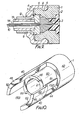
- the waveguide has a conventional protective sleeve 11 (or is of the double-sheath type having an outer mechanical protective sleeve 12, a woven fibrous sleeve 13 to prevent pull-out, and a second protective sleeve 14 - see Figure 9).
- a resilient split retaining cone 17 is disposed in the region of the bore, the cone 17 extending into the conical recess 16 in lens element 3.
- the cone includes an axial bore for receiving the fibre 10 stripped of protecting sleeve back to its entry into cone 17.
- the conical recess 16 in the lens element communicates with a short axial recess or bore 18 for receiving the end of fibre 10.
- a washer 20 is provided to provide support for the fibre 10 between cone 17 and cap 4 .
- the arrangement of cap 4, washer 20 and resilient cone 17 is such that the fibre 10 is firmly located in the housing 1, since as cap 4 is pushed onto housing 1, cone 17 is compressed to grip the fibre 10.
- the lens element is provided with a convex lens surface 21, which is spaced from the end 19 of bore 18 by a distance equal to the focal length of the lens so that light emitted from the end of fibre 10 in bore 18 travels through the translucent lens element 3 to the lens surface 21 from which it is emitted as a collimated beam of light.
- a convex lens surface 21 which is spaced from the end 19 of bore 18 by a distance equal to the focal length of the lens so that light emitted from the end of fibre 10 in bore 18 travels through the translucent lens element 3 to the lens surface 21 from which it is emitted as a collimated beam of light.
- annular shoulder 22 which projects forwardly of the lens surface 21, and terminates in a flat surface 23 which is perpendicular to the longitudinal axis of the lens element 3.
- the shoulders 22 of the two lens elements 3 abut each other at their respective faces 23. This mutual abutment ensures that the two lens elements are precisely aligned either coaxially or very close to coaxially.
- Lens element 3 is provided with an annular circumferential groove 24, and the bore 2 of housing 1 has one or more (three are shown in Figure 2) projections 25 which are received in groove 24 to retain element 3 within the bore 2.
- the lens element 3 is slid into bore 2 of housing 1 and snapped past the projections 25 (with temporary deformation of housing 1) until the projections engage in the groove 24.
- cap 4 and washer 20 in Figure 9 is slightly different from that shown in Figure 1 in that, in Figure 9, the bore 9 in cap 4 is enlarged to receive the extra protective sleeves on fibre 10, and the washer is profiled to engage the outer sleeve 12 against the inside of cap 4.
- the housing is provided with coupling means.
- the coupling means are formed as an integral part of the cylindrical housing 1.
- the housing has a pair of axially extending arms 40, which are of arcuate cross-section with an external diameter equal to that of the adjacent portion 42 of the housing, and an internal diameter greater than that of bore 2 in which the lens element is located.
- the arms are diametrically opposed and are each of a generally L-shape, one limb (44) of the "1" extending forward axially from housing portion 42 ani the other limb of the "L” extending circumferentially at the forward end of the limb 44, to form a key portion 46.
- the internal angle "P" of he "L” is less than 90°.
- each end face 48 of the arms.40 is less than one quarter of a circle.
- the wo arms 40 are two correspondingly L-shaped rece.ses 50 which each include an axially extending portion and a circumferentially extending portion 52.
- the L-shaved recesses are arranged to receive the L-shaped projectious of another terminal connector to be coupled therewich. Coupling is effected by moving the two termini. connector ends together whereby the pair of arms of each connector is received in the axially extebting portions of the corresponding recesses 50 in the ther connector.
- the key portions 46 lie adjacet the circumferentially extending recesses and by turning one connector by 1/8th turn relative to the other, tht key portions are received in the recesses to lock ti- two connectors together. Because angle P is less than 90 0 , the interengagement of key portions 46 and recesses 52 forms a positive lock against disengagement.
- housing 1 projects axially forwardly of portion 42, internally of arms 40, to provide a generally cylindrical portion 60 which underlies, and forms a lower surface in, each of the circumferential recesses 52.
- the outer surface of portion 60 has a step 61 adjacent each recess 52, and there is a corresponding step 62 on the inside of each arm 40.
- the purpose of the steps is to provide additional security against ingress or egress of light when the terminal connector is coupled to another connector or other member.
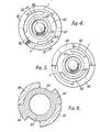
- portion 60 has an arcuate projection 65, of thickness less than that of the portion 60, and a diametrically opposed recess 66, the recess 66 being of greater arcuate length than projection 65.
- the projection 65 of each is received in the recess 66 of the other, and the recess is of greater arcuate length than the projection to allow the latter to slide circumferentially in the recess as one connector housing is turned l/8th turn to lock keys 46 in recesses 52.
- the projections 65 and recesses 66 lie in the regions "J" of portion 60 (see Figures 4 and 5) which are exposed when two connectors are coupled together. The engagement of the projections in the recesses prevents ingress or egress of light (see Figure 8).
- the connectors of Figures 1 to 10 can be coupled and decoupled manually without the use of special tools.
- the housing is preferably a one piece plastics moulding, but it may be in metal or other materials. It will normally have some inherent resilience.
- the connectors are positively held tightly together (by virtue of the resilience of the housing) to ensure that the two lens elements are in positive abutment via the projecting shoulders.
- coupling is effected by a "push and turn" operation.
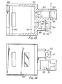
- Figures 11 to 29, Figures 11 to 14, 20 and 21 show the second part of a two-part connector comprising a housing 101 having an open end 102 (into which the first part is inserted) and, at the opposite end, two tubular projections 103, 104, in which lens elements 105 (broken lines in Figure 13) are received.
- Tubes 103 and 104 are parallel and each have an internal projection 107 to engage and retain therein a lens element 105 of the invention, the said lens elements each-having a corresponding annular recess 108 in which projection 107 engages.
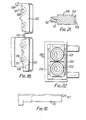
- the lens elements 105 ( Figure 21) comprise a cylindrical block of plastics material or glass having a lens surface 109 at one end, and a conical aperture 110 at the other end, narrowing down to a small bore 111 to receive the f.o.w.
- An '0' ring may be fitted over the narrower portion of element 105, to lie at 150, to act as a resilient buffer when the lens is in position in housing 101.
- Each tube 103, 104 has a lens element 105 mounted therein.
- Tube 103 extends beyond the lens element but in tube 104, which is shorter than tube 103, the lens element extends beyond the end 112 of the tube.
- the forward ends of the two lens elements 105 when assembled in tubes 103, 104 lie in the same plane (line P-P in Figure 13).
- lever clips ll5 On the outer side of tube 103, on the top and bottom sides of the connector, are mounted two lever clips ll5, each comprising a lever 116 pivoted about a support 117 with a tooth 118 at the forward end.
- the arrangement is such that when two connectors are aligned, with the longer tube 103 of each opposite the shorter tube 104 of the other, the webs 120 are received around the forward end of tubes 103 and teeth 118 clip into recesses 121 to hold the two connectors together (as in Figure 20). Pivoting the levers about supports 117 will release teeth 118 from recesses 121 to uncouple the assembly.
- the first part of the two part connector is shown in Figures 15 to 19. It comprises a generally rectangular solid base 130 moulded of plastics material, with a two-section lid (131,132) hinged thereto by integrally formed plastics web 133.
- the base comprises a pair of channels, each channel being in three sections of diminishing size, 134, 135, 136.
- the smallest channels 136 pass through half-cone projections 137.
- the two lid sections each have corresponding channels and half-cone projections (labelled prime) so that when the lid sections are closed over the base, the channels correspond to produce ducts for the f.o.w.
- Each lid section has a projecting clip 138 designed to engage in a corresponding recess 139 in base 130 to hold the lids releasably closed.
- Figures 16 and 17 show (in chain lines) the siting of an f.o.w. in the channels 135' and 136', respectively.
- This first part of the connector constitutes a cable clamp block and is used as follows.
- a two channel fibre optic cable has its various protective layers cut back to so that only bare fibre is laid in base channel 1 3 6, fibre with some protection is laid in channel 135, and channel 134 may accommodate the fully clad cable.
- the bare fibre should extend out of channel 136 beyond the tip of half-cone 137 by 2 mm.
- Kevlar reinforcement (a long staple man-made fibre) is provided in the cable to strengthen the connection between the cable and the connector. This is laid across the front portion of base 130 (adjacent half-cones 137) and may be glued in place using, for example, cyanoacrylate glue or another catalytic resin adhesive, or may simply be held in place when the second lid section 132 is snapped shut. Use of an adhesive is optional,. depending among other things on the pull-out strength required.
- the f.o.w. cable is now in a clamped position in the first part of the connector, with the f.o.w. ends projecting 2 mm beyond the tips of cones (137, 137').
- the assembly is now introduced (with the cones 137, 137' at the forward end) into open end 102 of housing.101, and slid forwardly therein (to the right in Figure 13).
- the cable block unit i.e. first part of the connector
- the cones (137, 137') enter the conical recesses 110 in the rear ends of lens elements 105.
- the protruding ends of the fibres will enter the bores 111 in lens elements 105 and hence be precisely positioned with respect to lens surfaces 109.
- a snap fit may be provided.
- the ends of the fibres will be smeared with matching gel or fluid.
- a moulded cap When the connector has been assembled, a moulded cap may be provided to fit over the ends of tubes 103, 104 to protect them until the connector is coupled to another connector or other station.
- an escutcheon plate For bulk head mounting, an escutcheon plate may be pushed along the outside of housing 101 until it meets a flange moulded half way along the body, where it engages and holds. It is also possible, of course, to mount the escutcheon directly on to a panel to lead the f.o.w. cables through a hole in the escutcheon plate, and then to push the connector half complete with cables back into the escutcheon plate until it engages with the snaps.
- the female one-piece connector of Figures 22 to 27 is generally similar to the two-part connector previously described in Figures 11 to 21. It comprises a body 200, the forward portion of which (right hand side of Figure 23) includes two parallel tubular portions 201, 202 each to receive a lens element 105 (as shown in Figure 21). Tube 201 is longer than the lens element, but tube 202 is shorter. The tubes communicate with the rear portion of the body 200 which comprises a cable connector 203 (the illustrated embodiment being for a two channel connection). Connector 203 comprises a solid base 204 having two sets of channels therein (205-208, and 209-212).
- Broad channels 205, 209 receive the clad cable
- narrower channels 206, 207, 210, 211 receive the cable with some of the protective cladding removed
- channels 208, 212 receive the bare fibre for insertion in the rear ends of lens elements 105.
- Hinged (by hinges 216) to the sides of base 203 are three lid sections 213, 214, 215.
- Lid section 213 has channels (labelled prime) corresponding to 205, 209 in the base, and lid section 214 has channels corresponding to 210, 206 in the base.
- the remaining portion of section 214, and section 215 are unchannelled.
- Each lid section has a clip 220 engageable in a corresponding recess 221 in base 203 when the lid is snapped shut.
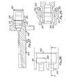
- the female connector of Figures 22-27 may be used with a male connector as shown in Figures 28 and 29.
- the male connector has a rear portion (not shown) which is the same as in Figures 22 to 27, and, at the forward end, similarly has two projecting tubular portions 250, 251 of different length, to receive lens elements.
- the male connector is offered up to the female. connector with tubular portions 250, 251, axially aligned with tubular portions 202, 201, respectively, and the arrangement is such that teeth 255 engage in recesses 231 to releasably couple the two connectors together.
- the respective forwards ends of tubes 201, 250 are (as shown) bevelled to fit snugly with the corresponding bevelled ends of tubes 202, 251.
- the f.o.w. is assembled in the connectors as follows.
- the fibre is first stripped back to pre-specified positions and then is then fitted into the open channels in the base 203.
- Space is provided for the fibre to be offset and placed in a small trough 260 at one end of the base, and the Kevlar reinforcement which comes between the fibre and the casing is laid back into the base and either held in place by closing a lid or actually glued in position.
- the sequence of actions to produce a finished termination consists in locking the outer covering of the fibre optic cable under the rear lid 213.
- the lid section 215 is closed to locate the two fibres in such a manner that they can still move backwards and forwards.
- the lenses 105 are then inserted in tubular portions 201, 202 (or 250, 251), and the open centre section of the base, which will be covered by lid 214, is observed to see whether the fibre has entered the whole of the lens by its movement.
- a set of marks can be provided on the base, beyond which marks the fibre should not move if it has been properly placed within the lens.
- connector of Figures 22 to 27 could be provided with hermaphrodite coupling means instead of the female/male arrangement illustrated.
- the connector of Figures 11 to 21 could be made with a male/ female coupling instead of the hermaphrodite coupling illustrated.
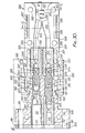
- Figure 30 shows an apertured support plate 301 for mounting on a bulkhead (not shown), a second connector 304 of the invention, for mounting via plate 301 on the bulkhead, a first connector body member 307 connected to the second connector 304, and a clamp block 308 connected to the first connector body 307.
- Plate 301 and connector 304 have aligned bores 310 for fixing bolts (not shown), and also aligned bores 311 and 312. Bore 311 of connector 304 receives a spacer sleeve 301 and a lens element 302 of the invention.
- the element 302 is a plastics moulding of stepped tubular form having a pair of lens surfaces (313, 314) formed therein.
- the tubular wall 315 extends forwardly of lens surface 314 and is generally parallel to the optical axis of lens 314. It terminates in a planar end portion 316.
- Wall 315 constitutes the projection of the invention in respect of the lens element 302.
- the tubular wall 317 extending rearwardly (to the left in Figure 30) of lens 313 is snugly received in the stepped bore 311 and, in use, will have a receiver or emitter therein.
- the other bore 312 of the second connector 304 has a sleeve 306 therein to the forward end (right hand side in Figure 30) of which is coupled a lens element 318 of the invention.
- Sleeve 306 is essentially the same as sleeves 330 in the first connector (see also Figures 33 to 36) and is later described with reference thereto.
- Lens element 318 is identical to lens elements 340 in the first connector and these are described later.
- the forward (right hand side of Figure 30) ends 316 and 319 of the lens elements 302 and 318 are coplanar and are within the respective bores 311 and 312 of the second.terminal 304.
- the outer part of terminal 304 includes a pair of recesses 320 to receive the engaging teeth 321 of finger clips 322 formed on the first terminal body 307.
- body 304 of the second connector has a groove or slot 323 in each bore 311, 312,to locate items received therein which may have a corresponding longitudinal rib.
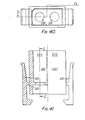
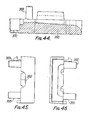
- the first connector 307 of Figure 30 is illustrated (without its constituent lenses and sleeves) in Figures 40 to 42.
- the body 307 is formed with two identical bores 331, 332 and a pair of outer finger clips 322 as previously described, which pivot about supports 325, for locking member 304 to member 307.
- a lens element of the invention 340 Within each of the bores (331, 332) of member 3 07 are located a lens element of the invention 340 and a sleeve 330.
- each sleeve 330 includes a bore 333 into which an f.o.w. (not shown) is fed.
- the left-hand end (Figure 30) of each sleeve 330 is shaped to receive in snap fit, the necked end portion of a lens element 340.
- each lens element bears against a rounded pivot bead 334 formed in bore 333 of sleeve 330, to allow the sleeve 330 to pivot about the end face 341 of the lens element.
- Sleeves 330 are pressed leftwards ( Figure 30) in the first connector (by the clamp block 308 to be described) and thus press lens elements 340 leftwards also into engagement with the respective lens elements 302, 318 of the second connector 304.
- Each lens element 340 is an elongate plastics moulding having a lens surface 34l at one end, with an annular flange 342 projecting forwardly thereof and terminating in a planar end face. As shown, flange 342 seats against the corresponding flange 342' on lens element 318 (and the projections 315 on lens element 302) to ensure that the respective pairs of lens elements 302, 340 and 318, 340 are axially aligned or at least have their axes parallel. At the other end of each lens element 340 is a conical recess 343 with a narrow central conical blind bore 344.
- Each recess 343 receives a bare fibre optical waveguide element, which may extend to the bottom of bore 344 or, if its diameter is larger than that of the bottom of the bore 344, it may jam against the side of the bore 344 above the bottom thereof.
- the focal point of lens 341 is in the bore 344 so that light emitted from a f.o.w. in bore 344 will be received by lens 34l and transmitted as a collimated beam of light to the adjacent lens element (318 or 304), and vice versa.
- pivot beads 334 in Figure 30 are 90° out of position (for illustration only). They thus permit body 307 of the first terminal, and its sleeves 330, to rock slightly about lens elements 340 without disturbing the alignment of the elements, due clearances being provided within bores 331, 332.
- This pivoting or rocking motion in Figure 30 is in a plane perpendicular to the plane of the drawing. Up to about 10° pivot can, for example, be provided in this way, whilst still keeping the respective lenses in contact and, so, aligned. Usually, about 5° pivot is satisfactory. If more than the permitted pivot is applied, the teeth 321 of the fasteners 322 slip out of the recesses 320 and so disconnect the first terminal 307 from the second terminal 304.
- Figures 34 to 36 show in more detail the sleeves 330 of Figure 30.
- the sleeve has a slot to render it expansible to receive, in snap fit, the necked end portion of a lens element 304.
- the sleeves have a narrower portion 337 to be received in the clamp block to be described.
- Figure 1 is a plan view of the lower part 350, comprising channel 351 (with ribs 352) which divides into two narrower channels 353, 354.
- Part 350 has two upstanding prongs 355 and two bores 356. It also has a spring clip 357, and a clip recess 358 and engaging tongue 359.
- the upper part 360 is exactly complementary e.g. it has two upstanding prongs which engage in lower part bores 356, and two bores which receive lower part prongs 355. It also has a corresponding spring clip and clip recess.
- a two channel f.o.w. cable is placed in the lower part 350, and part of the cladding stripped back to separate the two f.o.w.'s into respective channels 353, 354 so that each can enter a bore 333 in sleeves 330 of the first terminal.
- the upper part 360 is snap fitted onto the lower parts350 to hold the cable precisely and firmly therein.
- a pair of recesses 370 which receive ribs 371 upstanding from terminal body 307.
- the respective mating surfaces are sloped so that not only is the clamp block held to terminal body 307, but it is also biased to the left in Figure 31 to bear leftwards on the respective sleeves 330 which, in turn, as previously described, bear on the lens elements 340 to bias them to the left ( Figure 30). This ensures that the lens elements 340 are axially aligned with the lens elements 304, 318 in the second terminal 304.
- Figure 30 we have for illustrative purposes only, shown two different lens elements in the second connector 304. In fact, two identical lens elements could, of course, be used.
- Figure 30 shows a two channel connection for a bulkhead, but the first connector could alternatively be connected to another connector of similar form, so as to provide a connection between two two-channel cables. In the latter case, both the connectors would be able to rock or pivot about their respective lens elements. Whilst a two channel arrangement has been illustrated, it is to be understood that single channel and multi-channel connectors also fall within the scope of the invention.
- the lens element 400 is generally similar to lens elements 340 and 3 1 8 shown in Figure 30. It comprises an elongate body of translucent material 401, suitably clear acrylic, having a convex lens surface 402 formed at one end thereof. Projecting forwardly of the lens 402 is an annular outerwardly tapering flange 403 terminating in a flat end face 404 lying in a plane perpendicular to the optical axis of the lens 402. At the other end of lens element 400 is a recess 405 comprising a slightly tapering outer first portion 406, a more tapering second portion 407, a generally cylindrical portion 408 and finally a truncated conical inner portion 409 having an end 410.
- the recess is designed to receive a fibre optic waveguide (or waveguide bundle), the waveguide being received into the portion 408 and either extending to the end 410 of the recess or jamming against the tapering walls of portion 409.
- Figure 48 shows the portions 408 and 409 of recess 405 on an enlarged scale.
- the focal point of lens 402 lies either at the end face 410 of recess 405, or in the end portion 409. In this way, light emitted from a waveguide end in 409 travels through lens element body 401 and is emitted from lens 402 as a parallel beam of collimated light.
- the middle region of lens element 400 is necked (at 411) to provide the relative movement referred to previously in connection with Figures 30 to 46.
- Figure 49 is a lens element 420 similar to element 302 in Figure 30. It consists of a body of translucent material 421 in the form of a stepped tube. Lens element 422 has an elongate annular flange 423 extending around its periphery. The thickness of the flange narrows slightly to its outer end face 424 which is perpendicular to the lens axis. At the other side of body 421 is a cavity 425 for receiving an emitter or receiver.
- the lens element is principally for use in a bulkhead station or the like.
- Lens 422 receives a collimated-beam of light and focusses it into cavity 425 and on to a receiver therein (not shown).
- Flange 423 ensures alignment of the lens element with an element such as in Figure 47 (see Figure 30).
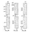
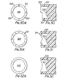
- Figures 50 to 52 illustrate alternative forms of flange for use in the lens elements of the invention.
- the flange is castellated so that (see also Figure 50A), it has two shorter quadrant sections 501, and two longer quadrant sections 502.
- the longer quadrant sections 502 of one element seat upon the shorter sections 501 of the other element.
- the end faces of the sections 501 are co-planar, as are the end faces of sections 502, and the said planes are perpendicular to the axis of the lens (the lens is referenced 505).
- Figures 51 and 51A show a flange 510 formed with a serrated end face 511 and in Figures 52 and 52A, the flange 520 is crenellated. In both cases, the flanges will engage with identical flanges on another lens element to hold the two elements with the optical axes of the lenses 505 in allign- ment.
Landscapes
- Physics & Mathematics (AREA)
- General Physics & Mathematics (AREA)
- Optics & Photonics (AREA)
- Optical Couplings Of Light Guides (AREA)
Applications Claiming Priority (6)
| Application Number | Priority Date | Filing Date | Title |
|---|---|---|---|
| GB8039276 | 1980-12-03 | ||
| GB8039276 | 1980-12-08 | ||
| GB8122612 | 1981-07-22 | ||
| GB8122612 | 1981-07-22 | ||
| GB8131165 | 1981-10-15 | ||
| GB8131165 | 1981-10-15 |
Publications (1)
| Publication Number | Publication Date |
|---|---|
| EP0053914A1 true EP0053914A1 (fr) | 1982-06-16 |
Family
ID=27261064
Family Applications (1)
| Application Number | Title | Priority Date | Filing Date |
|---|---|---|---|
| EP81305705A Withdrawn EP0053914A1 (fr) | 1980-12-03 | 1981-12-03 | Connecteurs à fibre optique et éléments à lentille pour ceux-ci |
Country Status (1)
| Country | Link |
|---|---|
| EP (1) | EP0053914A1 (fr) |
Cited By (17)
| Publication number | Priority date | Publication date | Assignee | Title |
|---|---|---|---|---|
| EP0078029A1 (fr) * | 1981-10-22 | 1983-05-04 | Felten & Guilleaume Fernmeldeanlagen GmbH | Connexion pour fibres optiques |
| EP0095280A1 (fr) * | 1982-05-24 | 1983-11-30 | AMP INCORPORATED (a Pennsylvania corporation) | Connecteur de fibres optiques avec une lentille |
| GB2139377A (en) * | 1983-05-07 | 1984-11-07 | Plessey Co Plc | Optical connectors |
| WO1986000422A1 (fr) * | 1984-06-22 | 1986-01-16 | Eastman Kodak Company | Connecteurs pour fibres optiques et composants de couplage |
| EP0195710A3 (fr) * | 1985-03-11 | 1988-09-14 | Itt Industries, Inc. | Dispositif d'alignement et de fixation de fibres optiques de transmission |
| EP0220690A3 (fr) * | 1985-10-28 | 1989-09-20 | GTE Laboratories Incorporated | Connecteur de fibre optique à faisceau lumineux élargi |
| US5208887A (en) * | 1990-01-22 | 1993-05-04 | Amp Incorporated | Method and apparatus for terminating a fiber-optic cable without adhesive |
| EP0241630B1 (fr) * | 1986-03-19 | 1993-05-19 | Ab Stratos Connectors | Méthode de connexion optique d'un bout de fibre optique avec un élément optique |
| US5216734A (en) * | 1992-06-12 | 1993-06-01 | Amp Incorporated | Fiber optic connector having low cost ferrule |
| WO1994000785A3 (fr) * | 1992-06-17 | 1994-03-03 | Whitaker Corp | Manchon terminal de guide d'ondes optique |
| WO2006105896A1 (fr) * | 2005-04-05 | 2006-10-12 | Rosenberger Hochfrequenztechnik Gmbh & Co. Kg | Cable de transmission de donnees pourvu d'un boitier de connexion optique de type fakra |
| EP2425287A4 (fr) * | 2009-04-28 | 2012-09-19 | Hewlett Packard Development Co | Coupleur coudé pour fibres optiques |
| WO2013180906A1 (fr) * | 2012-06-01 | 2013-12-05 | Tyco Electronics Corporation | Connecteur à faisceau dilaté à lentille moulée |
| US8827567B2 (en) | 2011-08-10 | 2014-09-09 | Tyco Electronics Corporation | Field-installable expanded beam connector system |
| WO2017012606A1 (fr) * | 2015-07-20 | 2017-01-26 | HARTING Electronics GmbH | Fiche optique |
| US9557488B2 (en) | 2011-01-11 | 2017-01-31 | Corning Incorporated | Optical connector with lenses having opposing angled planar surfaces |
| DE102013102023C5 (de) | 2013-03-01 | 2022-08-18 | Harting Electric Stiftung & Co. Kg | Optisches Modul für modular aufgebaute Industriesteckverbinder |
Citations (10)
| Publication number | Priority date | Publication date | Assignee | Title |
|---|---|---|---|---|
| DE2449359A1 (de) * | 1973-10-18 | 1975-04-24 | Western Electric Co | Koppelvorrichtung fuer optische fasern |
| GB1429843A (en) * | 1973-06-02 | 1976-03-31 | Plessey Co Ltd | Endwise coupling of light guides |
| DE2557660A1 (de) * | 1974-12-23 | 1976-07-01 | Western Electric Co | Verfahren und vorrichtung zum spleissen optischer fasern |
| DE2703887A1 (de) * | 1976-02-03 | 1977-08-04 | Itt Ind Gmbh Deutsche | Lichtleiteranschluss fuer optische koppelanordnungen |
| DE2711172A1 (de) * | 1976-03-18 | 1977-09-22 | Smiths Industries Ltd | Kupplungsstueck bei einer lichtleitstabvorrichtung |
| DE2711171A1 (de) * | 1976-03-18 | 1977-09-29 | Smiths Industries Ltd | Endstueck einer lichtleitstabvorrichtung |
| DE2722367A1 (de) * | 1976-05-25 | 1977-12-08 | Combined Optical Ind Ltd | Anordnung zum verlustarmen abschluss der enden von lichtleitern oder lichtleiterbuendeln |
| FR2394969A7 (fr) * | 1977-06-14 | 1979-01-12 | Fabregas De Palau Manuel | Coffre-fort |
| GB1572502A (en) * | 1976-08-06 | 1980-07-30 | Smiths Industries Ltd | Optical waveguide couplings |
| EP0032722A1 (fr) * | 1980-01-17 | 1981-07-29 | GTE Laboratories Incorporated | Connecteurs pour fibres optiques |
-
1981
- 1981-12-03 EP EP81305705A patent/EP0053914A1/fr not_active Withdrawn
Patent Citations (17)
| Publication number | Priority date | Publication date | Assignee | Title |
|---|---|---|---|---|
| GB1429843A (en) * | 1973-06-02 | 1976-03-31 | Plessey Co Ltd | Endwise coupling of light guides |
| FR2248521A1 (fr) * | 1973-10-18 | 1975-05-16 | Western Electric Co | |
| GB1475192A (en) * | 1973-10-18 | 1977-06-01 | Western Electric Co | Arrangement for connecting optical fibres |
| DE2449359A1 (de) * | 1973-10-18 | 1975-04-24 | Western Electric Co | Koppelvorrichtung fuer optische fasern |
| GB1524874A (en) * | 1974-12-23 | 1978-09-13 | Western Electric Co | Optical fibre waveguides |
| DE2557660A1 (de) * | 1974-12-23 | 1976-07-01 | Western Electric Co | Verfahren und vorrichtung zum spleissen optischer fasern |
| GB1569614A (en) * | 1976-02-03 | 1980-06-18 | Standard Telephones Cables Ltd | Optical fibre connectors |
| DE2703887A1 (de) * | 1976-02-03 | 1977-08-04 | Itt Ind Gmbh Deutsche | Lichtleiteranschluss fuer optische koppelanordnungen |
| DE2711171A1 (de) * | 1976-03-18 | 1977-09-29 | Smiths Industries Ltd | Endstueck einer lichtleitstabvorrichtung |
| DE2711172A1 (de) * | 1976-03-18 | 1977-09-22 | Smiths Industries Ltd | Kupplungsstueck bei einer lichtleitstabvorrichtung |
| GB1572501A (en) * | 1976-03-18 | 1980-07-30 | Smiths Industries Ltd | Optical waveguide assemblies |
| DE2722367A1 (de) * | 1976-05-25 | 1977-12-08 | Combined Optical Ind Ltd | Anordnung zum verlustarmen abschluss der enden von lichtleitern oder lichtleiterbuendeln |
| FR2353069A1 (fr) * | 1976-05-25 | 1977-12-23 | Combined Optical Ind Ltd | Raccords pour guides d'ondes optiques |
| GB1579027A (en) * | 1976-05-25 | 1980-11-12 | Combined Optical Ind Ltd | Fibre optic waveguide connectors |
| GB1572502A (en) * | 1976-08-06 | 1980-07-30 | Smiths Industries Ltd | Optical waveguide couplings |
| FR2394969A7 (fr) * | 1977-06-14 | 1979-01-12 | Fabregas De Palau Manuel | Coffre-fort |
| EP0032722A1 (fr) * | 1980-01-17 | 1981-07-29 | GTE Laboratories Incorporated | Connecteurs pour fibres optiques |
Cited By (27)
| Publication number | Priority date | Publication date | Assignee | Title |
|---|---|---|---|---|
| EP0078029A1 (fr) * | 1981-10-22 | 1983-05-04 | Felten & Guilleaume Fernmeldeanlagen GmbH | Connexion pour fibres optiques |
| EP0095280A1 (fr) * | 1982-05-24 | 1983-11-30 | AMP INCORPORATED (a Pennsylvania corporation) | Connecteur de fibres optiques avec une lentille |
| GB2139377A (en) * | 1983-05-07 | 1984-11-07 | Plessey Co Plc | Optical connectors |
| US4732452A (en) * | 1983-05-07 | 1988-03-22 | Plessey Overseas Limited | Optical connectors |
| WO1986000422A1 (fr) * | 1984-06-22 | 1986-01-16 | Eastman Kodak Company | Connecteurs pour fibres optiques et composants de couplage |
| US4723830A (en) * | 1984-06-22 | 1988-02-09 | Eastman Kodak Company | Optical fiber connectors |
| EP0195710A3 (fr) * | 1985-03-11 | 1988-09-14 | Itt Industries, Inc. | Dispositif d'alignement et de fixation de fibres optiques de transmission |
| EP0220690A3 (fr) * | 1985-10-28 | 1989-09-20 | GTE Laboratories Incorporated | Connecteur de fibre optique à faisceau lumineux élargi |
| EP0241630B1 (fr) * | 1986-03-19 | 1993-05-19 | Ab Stratos Connectors | Méthode de connexion optique d'un bout de fibre optique avec un élément optique |
| US5208887A (en) * | 1990-01-22 | 1993-05-04 | Amp Incorporated | Method and apparatus for terminating a fiber-optic cable without adhesive |
| US5216734A (en) * | 1992-06-12 | 1993-06-01 | Amp Incorporated | Fiber optic connector having low cost ferrule |
| WO1994000785A3 (fr) * | 1992-06-17 | 1994-03-03 | Whitaker Corp | Manchon terminal de guide d'ondes optique |
| WO2006105896A1 (fr) * | 2005-04-05 | 2006-10-12 | Rosenberger Hochfrequenztechnik Gmbh & Co. Kg | Cable de transmission de donnees pourvu d'un boitier de connexion optique de type fakra |
| US7824110B2 (en) | 2005-04-05 | 2010-11-02 | Rosenberger Hochfrequenztechnik Gmbh & Co. Kg | Data transmission cable with FAKRA housing |
| CN100543501C (zh) * | 2005-04-05 | 2009-09-23 | 罗森伯格高频技术有限及两合公司 | 有fakra外壳的数据传输缆线 |
| EP2425287A4 (fr) * | 2009-04-28 | 2012-09-19 | Hewlett Packard Development Co | Coupleur coudé pour fibres optiques |
| US9557488B2 (en) | 2011-01-11 | 2017-01-31 | Corning Incorporated | Optical connector with lenses having opposing angled planar surfaces |
| US8827567B2 (en) | 2011-08-10 | 2014-09-09 | Tyco Electronics Corporation | Field-installable expanded beam connector system |
| TWI610105B (zh) * | 2012-06-01 | 2018-01-01 | 太谷電子公司 | 具有模造透鏡之擴束型連接器 |
| CN104364685A (zh) * | 2012-06-01 | 2015-02-18 | 泰科电子公司 | 具有模制透镜的扩束型连接器 |
| US9588302B2 (en) | 2012-06-01 | 2017-03-07 | Te Connectivity Corporation | Expanded-beam connector with molded lens |
| WO2013180906A1 (fr) * | 2012-06-01 | 2013-12-05 | Tyco Electronics Corporation | Connecteur à faisceau dilaté à lentille moulée |
| DE102013102023C5 (de) | 2013-03-01 | 2022-08-18 | Harting Electric Stiftung & Co. Kg | Optisches Modul für modular aufgebaute Industriesteckverbinder |
| WO2017012606A1 (fr) * | 2015-07-20 | 2017-01-26 | HARTING Electronics GmbH | Fiche optique |
| CN107924029A (zh) * | 2015-07-20 | 2018-04-17 | 浩亭电子有限公司 | 光学插拔连接器 |
| US10139576B2 (en) | 2015-07-20 | 2018-11-27 | HARTING Electronics GmbH | Optical connector |
| CN107924029B (zh) * | 2015-07-20 | 2020-06-02 | 浩亭电子有限公司 | 光学插拔连接器 |
Similar Documents
| Publication | Publication Date | Title |
|---|---|---|
| US11592626B2 (en) | Fiber optic connector with boot-integrated release and related assemblies | |
| CA1255522A (fr) | Connecteur de fibres optiques | |
| US4515434A (en) | Fiber optic connector | |
| EP2035874B1 (fr) | Connecteur optique | |
| JP3569488B2 (ja) | 一体ハウジングを有する光学コネクタ | |
| US5971626A (en) | Fiber optic connector and connector sleeve assembly | |
| CA1063398A (fr) | Connecteur optique pour guide d'ondes | |
| EP0685750B1 (fr) | Connecteur pour connecter un câble à fibre optique | |
| US10324262B1 (en) | Field terminable fiber optic connectors | |
| MXPA06010746A (es) | Conector de fibra optica que se puede instalar en campo. | |
| CN101091131A (zh) | 可现场安装的光纤连接器 | |
| US11169332B2 (en) | Fiber optic connector with unitary housing and fiber optic connector assembly | |
| US4220397A (en) | Optical fiber connector | |
| US20220082763A1 (en) | Multi-fiber assembly for a ferrule-less fiber optic connector | |
| GB1563077A (en) | Connector for light conductive cables | |
| EP0421305B1 (fr) | Ensemble de connection à fibre optique | |
| EP3983839B1 (fr) | Connecteur de fibres optiques | |
| US6688782B1 (en) | Universal ferrule | |
| EP0064588B1 (fr) | Connecteur de fibres optiques | |
| US11061192B2 (en) | Multi-channel fiber optic cable connector | |
| IE20070439A1 (en) | An optical connector |
Legal Events
| Date | Code | Title | Description |
|---|---|---|---|
| PUAI | Public reference made under article 153(3) epc to a published international application that has entered the european phase |
Free format text: ORIGINAL CODE: 0009012 |
|
| AK | Designated contracting states |
Designated state(s): AT BE CH DE FR GB IT LU NL SE |
|
| 17P | Request for examination filed |
Effective date: 19821129 |
|
| STAA | Information on the status of an ep patent application or granted ep patent |
Free format text: STATUS: THE APPLICATION IS DEEMED TO BE WITHDRAWN |
|
| 18D | Application deemed to be withdrawn |
Effective date: 19840710 |
|
| RIN1 | Information on inventor provided before grant (corrected) |
Inventor name: PASCO, IAN KENNETH |