EP0064588B1 - Connecteur de fibres optiques - Google Patents
Connecteur de fibres optiques Download PDFInfo
- Publication number
- EP0064588B1 EP0064588B1 EP82102405A EP82102405A EP0064588B1 EP 0064588 B1 EP0064588 B1 EP 0064588B1 EP 82102405 A EP82102405 A EP 82102405A EP 82102405 A EP82102405 A EP 82102405A EP 0064588 B1 EP0064588 B1 EP 0064588B1
- Authority
- EP
- European Patent Office
- Prior art keywords
- connector
- holder
- holders
- housing
- fibers
- Prior art date
- Legal status (The legal status is an assumption and is not a legal conclusion. Google has not performed a legal analysis and makes no representation as to the accuracy of the status listed.)
- Expired
Links
- 239000000835 fiber Substances 0.000 title claims description 82
- 238000010168 coupling process Methods 0.000 claims description 13
- 238000000429 assembly Methods 0.000 claims description 9
- 230000008878 coupling Effects 0.000 claims description 9
- 238000005859 coupling reaction Methods 0.000 claims description 9
- 230000005540 biological transmission Effects 0.000 description 31
- 230000013011 mating Effects 0.000 description 12
- 238000000034 method Methods 0.000 description 5
- 238000004519 manufacturing process Methods 0.000 description 4
- 239000013307 optical fiber Substances 0.000 description 4
- 230000008569 process Effects 0.000 description 4
- 238000005253 cladding Methods 0.000 description 3
- 238000010276 construction Methods 0.000 description 3
- 230000008901 benefit Effects 0.000 description 2
- 238000006073 displacement reaction Methods 0.000 description 2
- 239000011521 glass Substances 0.000 description 2
- 239000002991 molded plastic Substances 0.000 description 2
- 230000001681 protective effect Effects 0.000 description 2
- 238000000926 separation method Methods 0.000 description 2
- 238000005299 abrasion Methods 0.000 description 1
- 230000000295 complement effect Effects 0.000 description 1
- 150000001875 compounds Chemical class 0.000 description 1
- 239000012530 fluid Substances 0.000 description 1
- 230000006872 improvement Effects 0.000 description 1
- 238000005304 joining Methods 0.000 description 1
- 239000000463 material Substances 0.000 description 1
- 239000002184 metal Substances 0.000 description 1
- 230000003287 optical effect Effects 0.000 description 1
- 238000004382 potting Methods 0.000 description 1
- 238000010079 rubber tapping Methods 0.000 description 1
- 239000007787 solid Substances 0.000 description 1
Images

Classifications
-
- G—PHYSICS
- G02—OPTICS
- G02B—OPTICAL ELEMENTS, SYSTEMS OR APPARATUS
- G02B6/00—Light guides; Structural details of arrangements comprising light guides and other optical elements, e.g. couplings
- G02B6/24—Coupling light guides
- G02B6/36—Mechanical coupling means
- G02B6/38—Mechanical coupling means having fibre to fibre mating means
- G02B6/3807—Dismountable connectors, i.e. comprising plugs
- G02B6/381—Dismountable connectors, i.e. comprising plugs of the ferrule type, e.g. fibre ends embedded in ferrules, connecting a pair of fibres
- G02B6/3826—Dismountable connectors, i.e. comprising plugs of the ferrule type, e.g. fibre ends embedded in ferrules, connecting a pair of fibres characterised by form or shape
- G02B6/383—Hermaphroditic connectors, i.e. two identical plugs mating with one another, each plug having both male and female diametrically opposed engaging parts
-
- G—PHYSICS
- G02—OPTICS
- G02B—OPTICAL ELEMENTS, SYSTEMS OR APPARATUS
- G02B6/00—Light guides; Structural details of arrangements comprising light guides and other optical elements, e.g. couplings
- G02B6/24—Coupling light guides
- G02B6/36—Mechanical coupling means
- G02B6/38—Mechanical coupling means having fibre to fibre mating means
- G02B6/3807—Dismountable connectors, i.e. comprising plugs
- G02B6/389—Dismountable connectors, i.e. comprising plugs characterised by the method of fastening connecting plugs and sockets, e.g. screw- or nut-lock, snap-in, bayonet type
-
- G—PHYSICS
- G02—OPTICS
- G02B—OPTICAL ELEMENTS, SYSTEMS OR APPARATUS
- G02B6/00—Light guides; Structural details of arrangements comprising light guides and other optical elements, e.g. couplings
- G02B6/24—Coupling light guides
- G02B6/36—Mechanical coupling means
- G02B6/38—Mechanical coupling means having fibre to fibre mating means
- G02B6/3807—Dismountable connectors, i.e. comprising plugs
- G02B6/3869—Mounting ferrules to connector body, i.e. plugs
-
- G—PHYSICS
- G02—OPTICS
- G02B—OPTICAL ELEMENTS, SYSTEMS OR APPARATUS
- G02B6/00—Light guides; Structural details of arrangements comprising light guides and other optical elements, e.g. couplings
- G02B6/24—Coupling light guides
- G02B6/36—Mechanical coupling means
- G02B6/38—Mechanical coupling means having fibre to fibre mating means
- G02B6/3807—Dismountable connectors, i.e. comprising plugs
- G02B6/3873—Connectors using guide surfaces for aligning ferrule ends, e.g. tubes, sleeves, V-grooves, rods, pins, balls
- G02B6/3885—Multicore or multichannel optical connectors, i.e. one single ferrule containing more than one fibre, e.g. ribbon type
Definitions
- This invention relates to an improved fiber optic connector and, more particularly, to separable connectors of the type in which multiple pairs of single strands or fibers are coupled to minimize light energy losses at the coupling.
- Fiber optic devices use single or multiple strands or fibers each having an inner circular glass core coated with a circumferential cladding having a different index of refraction. Light is transmitted along the core and totally reflected from the interface between the core and cladding. Such devices can be used as transmission lines for transmitting information bearing light energy.
- a transmission line can be formed from a single fiber or it can include a plurality of fibers bundled together as a cable. Additionally, several transmission lines can be arranged in parallel for the simultaneous transmission of information along each of the separate lines.
- the transmission line is relatively long and extends between different pieces of apparatus, the transmission line is broken down into segments and the different segments are connected to each other by use of separable fiber optic connectors which have been developed to meet this need.
- the principal design criteria of such connectors is to connect the transmission lines in an end-to-end relationship in such a manner as to minimize the loss of light energy as light traverses from one end of one line into the end of the adjacent segment of that line.
- the most efficient transfer of energy occurs when the axis of the two lines are in alignment. In other words, if the ends of the lines are out of alignment either due to a lateral displacement or to the fact that there is a slight angular displacement, light energy will be lost.
- most fiber optic connectors are designed to bring the ends of the transmission lines into as perfect an axial alignment as possible.
- U.S. patent 3 922 064, Clark et al discloses a "Self-aligning Optical Waveguide Connector" for a transmission line formed from a cable or bundle of fibers.
- the connector is for a single cable and includes provision of allowing both axial and lateral movement of the ends of at least one of the cable segments during the mating process.
- U.S. Patent 3 999 837, Bowen et al discloses a "Light Transmitting Fiber Bundle Connector" one embodiment of which is designed to connect a single transmission line and the other embodiment connects a plurality of transmission lines in parallel.
- Patent 3 982 815 shows a "Connector For Light Transmitting Cables" in which a single transmission line is connected by means of a connector formed of identical parts.
- the ends of one transmission line is spring biased to allow for some axial movement during the mating process.
- U.S. Patent 4008948 discloses "Optical Fibre Connectors" for either a single transmission line or plural parallel transmission lines. The ends of the individual lines are aligned in a specially shaped male member.
- U.S. Patent 4 056 305, McCartney et al shows a "Single Optical Fiber Connector Utilizing Elastomeric Alignment Device" for single and plural transmission lines. The ends of the individual fibers are brought into alignment by being passed through cylindrical guides biased by a surrounding elastomeric alignment element.
- U.S. Patent 4008948 discloses "Optical Fibre Connectors" for either a single transmission line or plural parallel transmission lines. The ends of the individual lines are aligned in a specially shaped male member.
- U.S. Patent 4 056 305, McCartney et al shows a "Single Optical Fiber Connector Utilizing Elastomeric Alignment Device" for single and plural transmission lines. The ends of the individual fibers are brought into alignment by being passed through cylindrical
- Patent 4 214 810 Stewart, discloses a "Method of Connecting Optical Fibers" in which two parallel transmission lines each terminate in one holder so that when the holders are brought together using alignment pins, the ends of the fibers are properly aligned.
- U.S. Patent 4 215 913, Turley et al discloses "Optical Fibre Connectors" for a single transmission line having self-centering guide means for causing alignment of the ends of the transmission line.
- the present invention was designed as an improvement upon the prior invention disclosed in European patent 25 65.
- two hermaphroditic housings carry a plurality of pairs of single fibers to be respectively coupled in such a manner as to have a high efficiency (low energy loss) connection.
- Each housing is identical and is constructed as a unitary element having a row of male members or plugs and a row of receptacles, through which the fibers extend.
- the male members and receptacles are specially shaped to bring the ends of mating pairs of fibers into end-to-end alignment. Because the diameters of the individual fibers are relatively small, the connector has to be built with tight, close or small tolerances to achieve a highly efficient connector.
- each housing is one piece.
- Another problem might arise during mating due to the fact that the forces which move the mating parts together and hold them are transmitted through the male members and receptacles with the result that some fiber ends might be forced out of alignment to thereby reduce coupling efficiency.
- the present invention was designed to avoid these problems.
- a fiber optic connector has two housings each of which carries a plurality of identical holders attached to the ends of the single fibers to be coupled.
- Each holder and fiber carried thereby is aligned with a mating holder and fiber in the other housing, when the connector is coupled, with the fiber ends axially aligned and adjacent to each other.
- the holders are biased toward a first position and are shaped to allow limited movement relative to the housings before the connector is fully coupled.
- the holders abut each other first and are then movable relative to the housing against the bias until the housings abut each other and provide a positive stop.
- the holders and fibers can move laterally and axially to correct for any slight mis-alignment.
- the invention provides a relatively inexpensive connector for aligning and coupling the ends of multiple pairs of single fiber optic transmission lines in such a manner as to efficiently transmit energy along the coupled fibers or transmission lines.
- the fiber optic connector according to the invention minimizes or overcomes alignment problems due to variation in manufacturing tolerances.
- the invention provides a fiber optic connector composed of two sub-assemblies, both of which use identical parts so as to reduce the cost due to having to otherwise make differently shaped parts.
- Specially shaped elements for aligning and connecting the ends of single mating fibers limit or prevent forces from being transmitted through the fibers.
- a fiber optic connector 10 comprises two identical sub-assemblies 11 and 12 for joining cables 15 and 18 which, as discussed below. contain parallel, fiber optic, single-fiber transmission lines.
- Sub-assembly 11 includes a housing 13 and support 14.
- sub-assembly 12 comprises a housing 16 and support 17 identical to 13 and 14 respectively.
- Cable 18 includes an elongated, flat, rubberlike, protective covering 19 of elongated rectangular cross-section provided with a series of slits through which a plurality of single fiber transmission line segments 21 can be inserted into the body of 19.
- Each fiber 21 has a circular glass core provided with a circumferential cladding and operates upon the fiber optic principle of total reflection to transmit light energy therealong.
- Protective coverings 22 surrounds fibers 21 within body 19. The ends of fibers 21 extend beyond the ends of coverings 22, as shown in Fig. 1, and have short unsupported sections before entering housing 16.
- Cable 15 is identical in construction. Both cables, in the illustrated embodiment, carry sixteen fibers 21 arranged in two rows of eight fibers in each row. When the segments in each cable are joined by connector 10, they form sixteen independent single fiber transmission lines for the transfer of information bearing light energy.
- Support 17 includes a flat, fan shaped body 24 upon which the end of cable 18 rests.
- a cross-bar 25 extends across one side of body 24.
- Two screws 26 are connected between the ends of cross-bar 25 and body 24 and lightly clamp cable covering 19 therebetween in such a manner as not to bend or deform the fibers 21 passing therethrough.
- Support 17 is formed in an identical manner and like parts bear like reference numerals.
- Supports 14 and 17 are respectively connected to housings 13 and 16 by screw means (not shown) and housings 13 and 16 are connected to each other by screw means 28 (Fig. 2) which hold connector 10 together yet allow it to be separated. Quite obviously, other forms of releasable or separable connecting means can be used.
- Housings 13 and 16 are each of a molded plastic material and are of identical construction so that only one need be described in detail. With reference primarily to Figs. 3-5, housing 13 comprises a pair of parallel slots 30 by means of which connector 10 may be mounted on the apparatus through which the transmission lines extend in such a manner, for example, that a sheet metal flange would fit into slots 30. Mounted within housing 13 are eight identical holders 31, a plate 32, and an elastomeric biasing means or cushion 37 (Figs. 7 and 8). Housing 13 has two sides, the connector side shown in Fig. 4 and the cable side shown in Fig. 5. On the connector side, an inverted U-shaped lip 33 overhangs a U-shaped lip 34.
- housing 13 Adjacent to lip 34, housing 13 has a U-shaped recess 35 adapted to receive the lip 33 of mating housing 16. Adjacent lip 33, housing 13 is open at area 36 so as to receive the corresponding lip 34 of housing 16 when the two housings are brought together.
- the hermaphroditic shapes of lips 33 and 34, slot 35 and area 36 permit the two housings to be joined together, mated or interfitted only when they are in a predetermined aligned orientation.
- the dimensions of the housing provide a loose interfit allowing some degree of relative angular and lateral movement during mating. This provides for a coarse alignment of holders 31 and fibers 21 when the housings are initially brought together.
- the central part of housing 13 is open so as to receive holders 31. As viewed in Fig.
- the upper edges of holders 31 have shallow V-shaped faces fitted into upper serrated edge 38 of the opening in housing 13, and the lower edges are bevelled or V-shaped and fit into a lower serrated edge 39.
- the clearances between the holders 31 and between the holders and the housing, including edges 38 and 39, provide a loose fit and permits the holders to freely move during the mating process. In other words, holders 31 are loosely mounted side-by-side in housing 13.
- housing 13 On the cable side (Fig. 5), housing 13 has a recess 40 into which plate 32 is placed and secured by screws 41. The cable side ends of holders 31 pass through plate 32 as shown in Figs. 7 and 8. Two laterally spaced counterbored holes 42 extend from the cable side through housing 13 and are adapted to receive two screws 28 for releasably fastening the holders (and connector) together.
- housing 13 On the connector side (Fig. 4), housing 13 further has two laterally spaced blind holes 43 which would receive the threaded ends of screws 28 mounted in the other housing. Holes 43 are either threaded or screws 28 can be self- tapping.
- each holder 31 is of a molded plastic and has an elongated relatively flat body of generally rectangular cross-section through bores of which two parallel fibers 21 extend.
- One fiber terminates at the end of a plug 47 and the other fiber terminates at the end or bottom of a receptacle 46.
- Each fiber 21 is of circular cross-section and has an end or end face perpendicular to the axis of the fiber.
- Plug 47 is coaxial with fiber 21 passing therethrough and has an enlarged base 47a, a tapered medial locating shoulder 47b and a tapered end portion or tip 47c of reduced diameter relative to sections 47a and b.
- Receptacle 46 has an enlarged outer bore 46a, a tapered shoulder 46b and an inner bore 46c which are circular cross-section and have an axis that is alig d with the axis of adjacent fiber 21.
- the shapes of plug 47 and receptacle 46 are complementary in that each plug is designed to fit into a corresponding receptacle on the other holder.
- Bore 46c has a circular edge, formed at the intersection of bore 46c and shoulder 46b, of a diameter between the inner and outer diameters of a shoulder 47b.
- shoulder 47b acts as a wedge against the edge of bore 46c and causes a lateral shift between the plug and receptacle to bring them into axial alignment.
- the adjacent ends of the fibers are spaced apart a slight distance such as .025 mm while the axis of the fibers are in exact alignment and the end faces of the fibers are parallel to each other. The reason for not having the fibers touch one another is to prevent any abrasion that might occur due to repeated coupling and decoupling of the fibers.
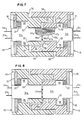
- cushion 37 is interposed between plate 32 and each holder 31a, 31b.
- the numerals 31 a and 31 b are used to more specifically designate each of the respective holders for understanding the explanation'described below.
- cushion 37 In the uncoupled position, cushion 37 bears against the cable side of tabs 48 and 49, there being a hole through the cushion through which the cable side of tab 31a extends.
- Cushion 37 biases tabs 48 and 49 towards abutment with a surface 52 on holder 13.
- holder 31a is moved to the left, as viewed in Fig. 7, towards the position shown in Fig. 8 wherein tabs 48 and 49 disengage from surface -52 while compressing cushion 37 still further.
- cushion 37 Upon separation or release of the mated connector, cushion 37 will cause the holders to move to the position shown in Fig. 7.
- sub-assemblies 11 and 12 are brought into rough alignment with the connector sides of housings 13 and 16 facing each other, the one sub-assembly being oriented 180° or upside down relative to the other. In such positions, holders 31 on each housing are aligned with each other. The sub-assemblies are then pushed or moved towards each other and at the same time the lips 33 and 34 of each are interfitted into spaces 36 and 35 on the other.
- lips and spaces form a rough guiding means to bring the housings 31a and 31b into rough alignment whereby the reduced or tapered tips 47c of the plugs are free upon further movement to enter into bores 46a of the receptacles.
- the length of lips 33 and 34 have to be slightly longer than the lengths of plugs 47 so that the rough alignment occurs first before the plugs can enter the receptacles. As further movement occurs, tips 47c of the plugs penetrate further into the receptacles until shoulders 47b contact the edge of bore 46c.
- each holder 31 There is sufficient clearance around each holder 31 so that should there be some slight lateral mis- alignment, the tapered tip 47c and eventually shoulder 47b would slide along the receptacle and cause a slight lateral shifting of the holders until they come into the exact alignment.
- shoulder 47a is seated, as shown in Fig. 7, further movement of the sub-assemblies towards each other causes the housings 13 and 16 to move until transverse face 56 on housing 13 engages transverse face 57 on housing 16 as shown in Fig. 8.
- holders 31a and 31 b are stationary relative to each other but move relative to the respective housings against the bias of cushions 37.
- Such bias is chosen so as to permit the above described movement to occur.
- cushions 37 suspend holders 31a and 31 axially therebetween and cushion any axial vibrations that might be imparted to the connector 10 and thereby minimize any movement that might occur as a result.
- the lengths of holders 31 a and 31 b are such that the cable sides are indented or flush with the cable sides of the housings, when the connector is fully coupled, so as not to project beyond the ends and hit the supports (Fig. 1).
- the portions requiring the greatest precision and the "tightest" manufacturing tolerances are the relative locations of edge of bore 46c and shoulder 47b within each holder. These locations have to be relatively precise so that the axis of a plug and receptacle align properly and thereby bring the fibers 21 extending therethrough into axial alignment. This precision can be aided by having all of the holders manufactured on a single die. The next order of precision is quite a bit less in that the holders are loosely interfitted side-by-side within the housings only to the extent that tips 47c of the plugs initially are free to enter enlarged bore 46a of the receptacles.
- the plugs and receptacles therein are formed as an integral one-piece body and therefore requires a continuously tight tolerance throughout the entire structure in order to precisely bring each of the fibers into the exact axial coupling alignment.
- the plugs 47 described above are of solid construction.
- the tips 47c may be split as described in the above mentioned European patent 25 65.
- Another advantage of the invention is that the parts of each sub-assembly 11 and 12 are identical and thus can be made more inexpensive because of higher volume production and the need for lower inventory of Darts.
Landscapes
- Physics & Mathematics (AREA)
- General Physics & Mathematics (AREA)
- Optics & Photonics (AREA)
- Mechanical Coupling Of Light Guides (AREA)
Claims (9)
Applications Claiming Priority (2)
| Application Number | Priority Date | Filing Date | Title |
|---|---|---|---|
| US06/263,237 US4405201A (en) | 1981-05-13 | 1981-05-13 | Fiber optic connector |
| US263237 | 1981-05-13 |
Publications (2)
| Publication Number | Publication Date |
|---|---|
| EP0064588A1 EP0064588A1 (fr) | 1982-11-17 |
| EP0064588B1 true EP0064588B1 (fr) | 1985-09-11 |
Family
ID=23000938
Family Applications (1)
| Application Number | Title | Priority Date | Filing Date |
|---|---|---|---|
| EP82102405A Expired EP0064588B1 (fr) | 1981-05-13 | 1982-03-23 | Connecteur de fibres optiques |
Country Status (4)
| Country | Link |
|---|---|
| US (1) | US4405201A (fr) |
| EP (1) | EP0064588B1 (fr) |
| JP (1) | JPS57186724A (fr) |
| DE (1) | DE3266116D1 (fr) |
Families Citing this family (14)
| Publication number | Priority date | Publication date | Assignee | Title |
|---|---|---|---|---|
| US4470660A (en) * | 1981-08-28 | 1984-09-11 | Harris Corporation | Blind mating rack and panel fiber optic connector |
| CA1247957A (fr) * | 1983-10-28 | 1989-01-03 | Ronald L. Mccartney | Oxymetre |
| US4723830A (en) * | 1984-06-22 | 1988-02-09 | Eastman Kodak Company | Optical fiber connectors |
| US4712861A (en) * | 1985-02-07 | 1987-12-15 | Northern Telecom Limited | Two-channel hermaphroditic fiber connector |
| US4953929A (en) * | 1989-07-21 | 1990-09-04 | International Business Machines | Fiber optic connector assembly and adapter for use therewith |
| US5133032A (en) * | 1991-04-17 | 1992-07-21 | Salter James R | Optical fiber connector |
| US5159654A (en) * | 1991-10-25 | 1992-10-27 | Optex Biomedical, Inc. | Multi-channel optical fiber connector |
| JP3066739B2 (ja) | 1996-07-15 | 2000-07-17 | セイコーインスツルメンツ株式会社 | 汎用光コネクタ及びベーシックプラグ |
| WO1999028774A1 (fr) * | 1997-11-28 | 1999-06-10 | Siemens Aktiengesellschaft | Systeme connecteur optique |
| US6471419B1 (en) | 1999-06-07 | 2002-10-29 | International Business Machines Corporation | Fiber optic assembly |
| JP5046406B2 (ja) * | 2010-03-26 | 2012-10-10 | ヒロセ電機株式会社 | コネクタ |
| CN106443900B (zh) | 2012-10-05 | 2019-08-09 | 3M创新有限公司 | 光学连接器 |
| WO2014080694A1 (fr) * | 2012-11-22 | 2014-05-30 | 京セラ株式会社 | Connecteur optique et module de transmission optique |
| DE102018201335B4 (de) * | 2018-01-29 | 2020-02-27 | Hahn-Schickard-Gesellschaft für angewandte Forschung e.V. | Lichtwellenleiter-steckverbinder, lichtwellenleiter-komplementärsteckverbinder und lichtwellenleiter-steckverbindung |
Family Cites Families (13)
| Publication number | Priority date | Publication date | Assignee | Title |
|---|---|---|---|---|
| JPS5710405B2 (fr) * | 1974-06-05 | 1982-02-26 | ||
| US3922064A (en) * | 1974-11-11 | 1975-11-25 | Deutsch Co Elec Comp | Self-aligning optical waveguide connector |
| US3999837A (en) * | 1975-01-03 | 1976-12-28 | Amp Incorporated | Light transmitting fiber bundle connector |
| US4008948A (en) * | 1975-06-30 | 1977-02-22 | Northern Telecom Limited | Optical fibre connectors |
| US4056305A (en) * | 1976-04-26 | 1977-11-01 | International Telephone And Telegraph Corporation | Single optical fiber connector utilizing elastomeric alignment device |
| GB1574044A (en) * | 1977-02-01 | 1980-09-03 | Plessey Co Ltd | Method of connecting optical fibres |
| US4167303A (en) * | 1977-07-28 | 1979-09-11 | Amp Incorporated | Light transmitting fiber cable connector |
| US4312564A (en) * | 1977-12-19 | 1982-01-26 | International Business Machines Corp. | Multi-fiber optic connector |
| FR2415314A1 (fr) * | 1978-01-19 | 1979-08-17 | Souriau & Cie | Module de connexion pour conducteurs optiques monobrins et connecteur muni de tels modules |
| US4252406A (en) * | 1978-09-05 | 1981-02-24 | The United States Of America As Represented By The Secretary Of The Army | Connector for optical fibers |
| DE2845420C2 (de) * | 1978-10-18 | 1984-11-08 | Bunker Ramo Corp., Oak Brook, Ill. | Lichtleiter-Steckverbindung |
| US4185886A (en) * | 1978-10-26 | 1980-01-29 | International Telephone And Telegraph Corporation | Fiber optic connector |
| GB2058392A (en) * | 1979-08-20 | 1981-04-08 | Gen Electric Co Ltd | Optical Fibre Connections |
-
1981
- 1981-05-13 US US06/263,237 patent/US4405201A/en not_active Expired - Lifetime
-
1982
- 1982-03-23 DE DE8282102405T patent/DE3266116D1/de not_active Expired
- 1982-03-23 EP EP82102405A patent/EP0064588B1/fr not_active Expired
- 1982-04-09 JP JP57058344A patent/JPS57186724A/ja active Pending
Also Published As
| Publication number | Publication date |
|---|---|
| DE3266116D1 (en) | 1985-10-17 |
| JPS57186724A (en) | 1982-11-17 |
| US4405201A (en) | 1983-09-20 |
| EP0064588A1 (fr) | 1982-11-17 |
Similar Documents
| Publication | Publication Date | Title |
|---|---|---|
| EP0002565B1 (fr) | Connecteur pour fibres optiques | |
| CA1063398A (fr) | Connecteur optique pour guide d'ondes | |
| US11874510B2 (en) | Optical assembly with cable retainer | |
| US4056305A (en) | Single optical fiber connector utilizing elastomeric alignment device | |
| US4405201A (en) | Fiber optic connector | |
| CA1239820A (fr) | Connecteur de fibres optiques | |
| US4458985A (en) | Optical fiber connector | |
| CA1053491A (fr) | Connecteur pour guide d'ondes optique | |
| CN103597389B (zh) | 具有开放的光纤夹紧槽的光纤连接器套圈 | |
| AU2012376219B2 (en) | High density multi-fiber for optical fiber connector | |
| US5737463A (en) | Massive parallel optical interconnect system | |
| EP0078547A2 (fr) | Connecteur optique | |
| EP0015291B1 (fr) | Piece de raccordement pour fibres optiques | |
| US4146299A (en) | Optical waveguide connectors for multiple waveguide cables | |
| US4385801A (en) | Fibre-to-fibre connector including a component for joining it to an optical cable | |
| US4323300A (en) | Optical fibre connectors | |
| US5179607A (en) | Fluted, high efficiency fiber optic adapter | |
| US6616462B2 (en) | Convertible multi-diameter sleeve for optical fiber connectors | |
| EP0053914A1 (fr) | Connecteurs à fibre optique et éléments à lentille pour ceux-ci | |
| GB1563077A (en) | Connector for light conductive cables | |
| US9279945B2 (en) | Methods, apparatuses and systems for blind mating arrays of multi-optical fiber connector modules | |
| US5339377A (en) | Optical fiber splicer for ribbon-shaped optical fiber cords | |
| US6688782B1 (en) | Universal ferrule | |
| EP0015657A2 (fr) | Connecteur de fibre optique | |
| US5216736A (en) | Welded splice element |
Legal Events
| Date | Code | Title | Description |
|---|---|---|---|
| PUAI | Public reference made under article 153(3) epc to a published international application that has entered the european phase |
Free format text: ORIGINAL CODE: 0009012 |
|
| AK | Designated contracting states |
Designated state(s): DE FR GB |
|
| 17P | Request for examination filed |
Effective date: 19830322 |
|
| GRAA | (expected) grant |
Free format text: ORIGINAL CODE: 0009210 |
|
| AK | Designated contracting states |
Designated state(s): DE FR GB |
|
| REF | Corresponds to: |
Ref document number: 3266116 Country of ref document: DE Date of ref document: 19851017 |
|
| ET | Fr: translation filed | ||
| PLBE | No opposition filed within time limit |
Free format text: ORIGINAL CODE: 0009261 |
|
| STAA | Information on the status of an ep patent application or granted ep patent |
Free format text: STATUS: NO OPPOSITION FILED WITHIN TIME LIMIT |
|
| 26N | No opposition filed | ||
| PGFP | Annual fee paid to national office [announced via postgrant information from national office to epo] |
Ref country code: GB Payment date: 19920210 Year of fee payment: 11 |
|
| PGFP | Annual fee paid to national office [announced via postgrant information from national office to epo] |
Ref country code: FR Payment date: 19920227 Year of fee payment: 11 |
|
| PGFP | Annual fee paid to national office [announced via postgrant information from national office to epo] |
Ref country code: DE Payment date: 19920321 Year of fee payment: 11 |
|
| PG25 | Lapsed in a contracting state [announced via postgrant information from national office to epo] |
Ref country code: GB Effective date: 19930323 |
|
| GBPC | Gb: european patent ceased through non-payment of renewal fee |
Effective date: 19930323 |
|
| PG25 | Lapsed in a contracting state [announced via postgrant information from national office to epo] |
Ref country code: FR Effective date: 19931130 |
|
| PG25 | Lapsed in a contracting state [announced via postgrant information from national office to epo] |
Ref country code: DE Effective date: 19931201 |
|
| REG | Reference to a national code |
Ref country code: FR Ref legal event code: ST |