EP0053916B1 - Système de commande pour un moteur à induction employant un onduleur comme générateur de courant alternatif - Google Patents
Système de commande pour un moteur à induction employant un onduleur comme générateur de courant alternatif Download PDFInfo
- Publication number
- EP0053916B1 EP0053916B1 EP19810305711 EP81305711A EP0053916B1 EP 0053916 B1 EP0053916 B1 EP 0053916B1 EP 19810305711 EP19810305711 EP 19810305711 EP 81305711 A EP81305711 A EP 81305711A EP 0053916 B1 EP0053916 B1 EP 0053916B1
- Authority
- EP
- European Patent Office
- Prior art keywords
- flow
- inverter
- function
- power factor
- power
- Prior art date
- Legal status (The legal status is an assumption and is not a legal conclusion. Google has not performed a legal analysis and makes no representation as to the accuracy of the status listed.)
- Expired
Links
- 230000006698 induction Effects 0.000 title claims description 34
- 230000003247 decreasing effect Effects 0.000 claims description 23
- 238000006243 chemical reaction Methods 0.000 claims description 4
- 230000002401 inhibitory effect Effects 0.000 claims 1
- 230000007423 decrease Effects 0.000 description 20
- 238000001914 filtration Methods 0.000 description 9
- 238000001514 detection method Methods 0.000 description 5
- 238000010276 construction Methods 0.000 description 4
- 239000003990 capacitor Substances 0.000 description 3
- 230000008859 change Effects 0.000 description 3
- 238000010586 diagram Methods 0.000 description 3
- 238000013461 design Methods 0.000 description 2
- 230000000694 effects Effects 0.000 description 2
- 238000000034 method Methods 0.000 description 2
- 238000012544 monitoring process Methods 0.000 description 2
- 230000008569 process Effects 0.000 description 2
- 230000009467 reduction Effects 0.000 description 2
- 238000004804 winding Methods 0.000 description 2
- 238000013459 approach Methods 0.000 description 1
- 230000001419 dependent effect Effects 0.000 description 1
- 238000002474 experimental method Methods 0.000 description 1
- 238000009499 grossing Methods 0.000 description 1
- 238000012545 processing Methods 0.000 description 1
- 230000004044 response Effects 0.000 description 1
Images




Classifications
-
- H—ELECTRICITY
- H02—GENERATION; CONVERSION OR DISTRIBUTION OF ELECTRIC POWER
- H02P—CONTROL OR REGULATION OF ELECTRIC MOTORS, ELECTRIC GENERATORS OR DYNAMO-ELECTRIC CONVERTERS; CONTROLLING TRANSFORMERS, REACTORS OR CHOKE COILS
- H02P27/00—Arrangements or methods for the control of AC motors characterised by the kind of supply voltage
- H02P27/04—Arrangements or methods for the control of AC motors characterised by the kind of supply voltage using variable-frequency supply voltage, e.g. inverter or converter supply voltage
- H02P27/06—Arrangements or methods for the control of AC motors characterised by the kind of supply voltage using variable-frequency supply voltage, e.g. inverter or converter supply voltage using DC to AC converters or inverters
-
- H—ELECTRICITY
- H02—GENERATION; CONVERSION OR DISTRIBUTION OF ELECTRIC POWER
- H02P—CONTROL OR REGULATION OF ELECTRIC MOTORS, ELECTRIC GENERATORS OR DYNAMO-ELECTRIC CONVERTERS; CONTROLLING TRANSFORMERS, REACTORS OR CHOKE COILS
- H02P27/00—Arrangements or methods for the control of AC motors characterised by the kind of supply voltage
- H02P27/04—Arrangements or methods for the control of AC motors characterised by the kind of supply voltage using variable-frequency supply voltage, e.g. inverter or converter supply voltage
- H02P27/047—V/F converter, wherein the voltage is controlled proportionally with the frequency
Definitions
- This invention relates to a control system for an induction motor using an inverter for AC power supply and more particularly to a control system which can improve the efficiency of this type of induction motor under light-load conditions.
- An induction motor drive system wherein three-phase AC power of constant voltage and constant frequency is converted into DC power by a converter, and the DC power is converted by an inverter into a three-phase AC power of variable frequency and voltage, which is supplied to the induction motor for driving the same is widely used when a wide range of speed control is required for induction motors.
- the so-called constant V/f ratio control in which the voltage V of the AC output is also changed to keep V/f constant is usually employed in order to maintain the output torque of the induction motor constant.
- V and I AC input voltage and current supplied to an induction motor
- cos cp the input power to the motor
- Vlcos p which is the sum of a motor load and a motor loss.
- the input voltage can be adjusted over a wide range without failure to maintain the motor output corresponding to its load, so that it can be reasonably expected that the motor loss can advantageously be decreased by decreasing the input voltage.
- the inventors of this invention have found that the power factor of the motor in operation can be estimated from an input current to the inverter.
- the motor drive system is typically provided with an input current detector for monitoring over-loading of the motor and the detection of this detector can therefore be utilized for estimation of the motor power factor, thus making it possible to use the power factor as a controlling factor without additional provision of an independent power factor detecting circuit.
- the present invention is based on the above findings and may enable the provision of a control system for an induction motor using an inerter which can decrease the motor loss under light-load conditions and which is simple in construction without either a power factor detecting circuit or a power detecting circuit.
- a control system for an induction motor in accordance with claim 1.
- a power factor detector which is as claimed in claim 1.
- an induction motor assembly employing the above control system or the above power factor detector.
- a drive circuit for an induction motor to which the invention is applied has a construction as shown in Fig. 1.
- a constant voltage and frequency three-phase AC power source 1 is connected to a converter 2 for conversion of AC to DC.
- the converter 2 is connected via DC buses 15 to a transistor inverter 4.
- Connected across the DC buses 15 is a smoothing capacitor 3.
- the inverter 4 is connected to an induction motor winding 5 of three phases U, V and W.
- DC current flowing through the DC buses 15 has a flow-in component I A to the inverter 4 and a flow-out component 1 8 therefrom as shown at section C in Fig. 2.
- Line voltage across the U and W phases of the induction motor winding 5 has a waveform as shown at Fig. 2a and the current flowing through the U phase has a waveform as shown in Fig. 2b.
- the power factor increases with increase of the motor load and the function 5 increases correspondingly with the power factor.
- Fig. 4 shows that the power factor decreases with increase of the frequency; and the function 6 decreases correspondingly with the power factor. Accordingly, the estimation of the power factor can be done by detection of the current flowing through the DC buses 15 i.e., DC current into the inverter, and applying it to the equation (1) without providing any conventional power factor detecting device.
- the so-called constant V/f ratio control is typically adopted in which V/f ratio is held constant by changing the output voltage V for the purpose of maintaining the output torque of the motor constant.
- the V/f ratio is preferably set to a value corresponding to a rated voltage V o and a rated frequency f o of the motor.
- the output voltage V exceeds kM ⁇ f (the output frequency of the inverter being f)
- an exciting current of the motor increases, resulting in an increased power loss. Accordingly, the output voltage V is required to be where for decreasing the power loss.
- the design of the induction motor is such that a maximum efficiency can be attained when the induction motor is operated at full load with an AC input of its rated voltage V o and frequency f o , the maximum efficiency is attained with an input voltage V(V ⁇ V M ) which is lower than the rated voltage V when the load is decreased and the value of V changes with the motor design and the magnitude of load.
- V(V ⁇ V M ) which is lower than the rated voltage V when the load is decreased and the value of V changes with the motor design and the magnitude of load.
- an excessive decrease of the input voltage V results in failure to maintain the torque required for the load and should be inhibited.
- a constant k L is determined depending on the degree of an intended light load and a lower limit V L of the input voltage is set to for the input frequency of f.
- the power factor estimating function 6 may be obtained from flow-in and flow-out components I A and I B of the input current of the inverter as described hereinbefore, and control may be carried out such that when ⁇ > ⁇ 1 the inverter output voltage V is increased but not allowed to exceed the upper limit V M and when ⁇ 2 , V is decreased but not allowed to be less than the lower limit V L .
- the relations between the input voltage V and the function 6, power factor cos ⁇ and input power P 1M are obtained as graphically depicted in Fig. 5.
- the power factor cos ⁇ increases, while the input power, i.e. the power loss P 1M decreases, but reaches its minimum point when the input voltage V is about 70 volts, where the motor is at the highest efficiency.
- a circuit arrangement for a control system embodying the invention will now be described with reference to Fig. 6 in which the same elements as those of Fig. 1 are designated by the same reference numerals.
- a DC current transformer 9 insulated from a DC bus 15 is inserted therein for detection of input current to an inverter.
- the output of the DC current transformer 9 is connected to an amplifier 10.
- the output of the amplifier 10 is fed two ways, one of which is connected to an A/D converter 7A of an inverter control circuit 7 via a flow-in component detecting circuit 11 adapted to detect a flow-in component I A of DC current and a filter 12.
- the other is connected to the A/D converter 7A via a flow-out component detecting circuit 13 adapted to detect a flow-out component I B of the Dc current and a filter 14.
- Applied to the A/D converter 7A is an output signal f of a frequency command potentiometer which sets a frequency corresponding to a target of revolutions of the induction motor.
- Signals I A , I B and f are converted by the A/D converter 7A into digital signals and applied to an operation unit 8.
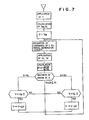
- the operation unit 8 constituted by a microcomputer, for example, prepares, as will be seen from the flow chart of Fig. 7, command signals for an inverter output voltage V and frequency f and applies them to a gate signal generator circuit 7B of the inverter control circuit 7.
- the gate signal generator circuit 7B In response to these command signals, the gate signal generator circuit 7B generates a gate signal which is applied to transistors or thyristors constituting the inverter 4.
- the inverter 4 then generates an AC output
- the microcomputer receives a digital signal f corresponding to a desired frequency of the motor from the A/D converter circuit, computes and and stores the computed values of V M and V L .
- the inverter 4 is responsive to these command signals to generate an AC output of voltage V M and frequency f which in turn drives the induction motor 5.
- a current dependent on the load on the motor flows through the inverter and its flow-in component I A and flow-out component I B are detected.
- the detected values are converted by the AID converter 7A into digital signals and then read by the microcomputer, which calculates a power factor estimating function 5 based on I A and I B .
- the calculated ⁇ is compared with its upper and lower limits ⁇ 1 and ⁇ 2 and it is decided which range the ⁇ belongs to, ⁇ > ⁇ 1 ⁇ 2 ⁇ 1 or ⁇ 2 .
- the processing proceeds with one of the following routines depending on the decided range
- Fig. 8 illustrates the process of changing V and 5 as mentioned above, where the abscissa represents the inverter output voltage or the motor input voltage V and the ordinate represents the power factor estimation function 5. As described above, where the motor load is fixed, the increase of the motor input voltage V is followed by the decrease of ⁇ .
- FIG. 8 illustrates the relation between V and 5 in the cases of motor loads P 1 , P 2 and P 3 (P 1 >P 2 >P 3 ) as parameters.
- the motor voltage V is V M at the time of starting. If the load is P 2 , the motor is driven at point A 1 where 5 is below 6 2 . Accordingly, V is decreased stepwise by ⁇ V so that 5 is increased to reach point A 2 within the range between ⁇ 1 and 5 2 , thus stopping the decrease of V. Under this condition, if the load increases to P 1 5 is also increased so that the motor driving condition is shifted to point A 5 where ⁇ > ⁇ 1 .
- the control operates to increase V stepwise by ⁇ V, causing 5 to decrease gradually. But, V is not allowed to exceed the upper limit V M and hence the ultimate state at point A 6 is held. If the motor load is decreased from P 2 to P 3 , ⁇ is then decreased and the motor driving condition is shifted from point A 2 to point A3 where ⁇ 2 . Then V is decreased stepwise by ⁇ V, causing 5 to increase gradually. But, V is not allowed to decrease below V L and the ultimate state at point A4 is held.
- the range of values of the function 5 is decided independently of the magnitude of the load, and the inverter output voltage V is controlled on the basis of the results of the decision.
- the controllable range of V is restricted by the upper limit V M , so that the contribution which control of V can make to the reduction of loss is limited.
- the induction motor inherently gives high efficiency and hence the control of the power factor estimation function 6 is of less, or no significance. Accordingly, the control of the function ⁇ may be applied only during light load conditions. In this case, the range of load which makes effective the control depends on characteristics of the motor and possible load conditions.
- FIG. 9 shows a circuit arrangement adapted for the utilization of the flow-in component I A and the flow-out component I B in such a manner as mentioned above. Specifically, this circuit arrangement substitutes for the circuits connected between the output of the DC current transformer 9 and the input of the inverter control circuit 7 in Fig. 6.
- this circuit arrangement comprises an inverting amplifier 21 connected to a DC current transformer 9, an inverting circuit 22, a first half-wave rectifying and filtering circuit 23, a second half-wave rectifying and filtering circuit 24, a comparator 20, a gain switchover circuit 26, a flow-in component amplifier 27, and a flow-out component amplifier 28.
- the first and second half-wave rectifying and filtering circuits 23 and 24 have the same construction, having each an amplifier.
- An amplifier A 1 of the first half-wave rectifying and filtering circuit 23 has a negative input terminal connected to the output of the inverting amplifier 21 via a resistor R 1 and to the output of the amplifier A 1 via a parallel circuit including a capacitor C, a resistor R 2 and a diode D 1 .
- Connected between one end of the resistor R 2 and the cathode of the diode D 1 is a diode D 2 which is cooperative with the diode D 1 to complete rectifying effect.
- the amplifier A 1 has a positive input terminal grounded via a resistor R 3 .
- the flow-in component amplifier 27 and the flow-out component amplifier 28 are of similar construction, each having an amplifier having a negative input terminal connected to a half-wave rectifying and filtering circuit.
- an amplifier unit A 2 of the flow-in component amplifier 27 has its negative input terminal connected through a resistor R 4 to the first half-wave rectifying and filtering circuit 23. Its positive input terminal is grounded via a resistor R 8 .
- the negative input terminal is also connected to the output of the amplifier unit A 2 via resistors R 5 and R 6 .
- Connected across the resistor R 6 is a normally open switch 26a.
- the flow-out component amplifier 28 has an amplifier unit A 2 having its negative input terminal connected to the output of the amplifier unit A 2 via a resistor across which a normally open switch 26b is connected.
- the outputs of the flow-in component amplifier 27 and flow-out component amplifier 28 are connected to input terminals of an inverter control circuit 7.
- the output of the first half-wave rectifying and filtering circuit 23 is connected to the gain switchover circuit 26 via the comparator 20.
- This gain switchover circuit 26 is operatively connected to the flow-in component amplifier 27 and the flow-out component amplifier 28.
- a signal from the DC current transformer 9 is inverted and amplified at the inverting amplifier 21.
- a flow-in component I A contained in an output signal of the inverting amplifier 21 is selected by half-wave rectification, then smoothed by the capacitor C and amplified at a constant gain determined by the resistors R 1 and R 2 so as to be delivered out as a flow-in component average value I Aab .
- a flow-out component I B contained in the output signal of the inverting amplifier 21 is selected by half-wave rectification, smoothed and amplified at a fixed gain to be delivered out as a flow-out component average value I Bab .
- the flow-in component average value I Aab is then coupled to the comparator 20 and compared with a predetermined levet I L . Then, as shown at a and b in Fig. 10, the comparator 20 feeds to the gain switchover circuit 26 a low level signal when the flow-in component average value I Aab is below the predetermined level I L and a high level signal when the I Aab exceeds the level I L . Upon receipt of the high level signal, the gain switchover circuit 26 produces an output signal which closes the switches 26a and 26b included in the amplifiers 27 and 28 thereby to reduce the gain of the flow-in component amplifier 27 by about 1/2 to 1/4 and to reduce the gain of the flow-out component amplifier 28 to zero.
- the flow-in component amplifier 27 produces an output signal as shown in Fig. 10c.
- the reason why the gain of the flow-in amplifier 27 is reduced as described above is that the output of the flow-in component amplifier 27 is desired to be prevented from saturation even when the inverter is accidentally subjected to arm short-circuit.
- the output of the flow-out component amplifier 28 falls to zero as shown in Fig. 10d when the flow-in component exceeds l u . Consequently, only the output of the flow-in component amplifier 27 is supplied to a microcomputer 8 via the inverter control circuit 7 to be used for detection of the DC input current.
- the DC current is detected by a current transformer
- the invention may use any other type of detector whose output follows a waveform of the current flowing through the DC bus.
- another function ⁇ of the flow-in and flow-out components I A and I B may be used as a power factor estimation function.
Landscapes
- Engineering & Computer Science (AREA)
- Power Engineering (AREA)
- Control Of Ac Motors In General (AREA)
Claims (7)


Applications Claiming Priority (4)
| Application Number | Priority Date | Filing Date | Title |
|---|---|---|---|
| JP17095380A JPS5797392A (en) | 1980-12-05 | 1980-12-05 | Controlling method for induction motor with inverter |
| JP170953/80 | 1980-12-05 | ||
| JP56101176A JPS586092A (ja) | 1981-07-01 | 1981-07-01 | インバ−タを用いた誘導電動機の直流電流および力率検出装置 |
| JP101176/81 | 1981-07-01 |
Publications (2)
| Publication Number | Publication Date |
|---|---|
| EP0053916A1 EP0053916A1 (fr) | 1982-06-16 |
| EP0053916B1 true EP0053916B1 (fr) | 1985-05-08 |
Family
ID=26442089
Family Applications (1)
| Application Number | Title | Priority Date | Filing Date |
|---|---|---|---|
| EP19810305711 Expired EP0053916B1 (fr) | 1980-12-05 | 1981-12-03 | Système de commande pour un moteur à induction employant un onduleur comme générateur de courant alternatif |
Country Status (3)
| Country | Link |
|---|---|
| US (1) | US4420718A (fr) |
| EP (1) | EP0053916B1 (fr) |
| DE (1) | DE3170436D1 (fr) |
Families Citing this family (19)
| Publication number | Priority date | Publication date | Assignee | Title |
|---|---|---|---|---|
| DE3245395A1 (de) * | 1981-12-09 | 1983-10-20 | Zinser Textilmaschinen Gmbh, 7333 Ebersbach | Verfahren und einrichtung zum verringern der leistungsaufnahme von elektrischen antriebssystemen |
| DE3307623C2 (de) * | 1983-03-04 | 1986-06-05 | Lenze GmbH & Co KG Aerzen, 3258 Aerzen | Verfahren und Schaltungsanordnung zur Regelung eines Wechselstrom- oder Drehstrommotors |
| US4550282A (en) * | 1983-03-09 | 1985-10-29 | Institut Cerac S.A. | Method and device for controlling a brushless alternating current motor |
| EP0159000B1 (fr) * | 1984-04-16 | 1990-07-11 | Hitachi, Ltd. | Méthode et appareil pour commander des inverseurs à l'impulsion modulée en largeur |
| DE3517694A1 (de) * | 1984-05-21 | 1985-11-21 | Mitsubishi Electric Corp | Steuerschaltung fuer einen inverter |
| JPS62221897A (ja) * | 1986-03-24 | 1987-09-29 | Mitsubishi Electric Corp | 電動機の制御装置 |
| SE452934B (sv) * | 1986-04-14 | 1987-12-21 | Elfi Innovationer | Sett och anordning for att driva en via en vexelriktare varvtalsreglerad asynkronmotor |
| FR2599196B1 (fr) * | 1986-05-21 | 1993-03-12 | Telemecanique Electrique | Convertisseur de frequence pour l'alimentation stabilisee de moteurs asynchrones |
| DE3625502C1 (en) * | 1986-07-28 | 1987-10-01 | Lenze Gmbh & Co Kg Aerzen | Circuit arrangement for supplying an AC motor or three-phase motor via a pulse-controlled invertor (pulse-width-modulated invertor) |
| JPH03155392A (ja) * | 1989-11-10 | 1991-07-03 | Toshiba Corp | 電流検出装置 |
| RU2136103C1 (ru) * | 1998-06-30 | 1999-08-27 | АО "Научно-производственное предприятие "Сапфир" | Частотно-регулируемый электропривод переменного тока |
| US6442979B1 (en) * | 1999-05-06 | 2002-09-03 | Emerson Electric Co. | Washing machine motor control device and method |
| US6636011B2 (en) * | 2001-06-13 | 2003-10-21 | Emerson Electric Co. | Induction motor control system |
| JP4471076B2 (ja) * | 2003-09-19 | 2010-06-02 | 株式会社安川電機 | Pwmサイクロコンバータ |
| RU2326775C2 (ru) * | 2006-04-14 | 2008-06-20 | Казанский государственный энергетический университет (КГЭУ) | Способ управления моментом электродвигателей переменного тока формированием в электроприводе частотно-регулируемого сигнала и устройство, реализующее этот способ |
| US7696715B2 (en) * | 2006-09-26 | 2010-04-13 | The Boeing Company | Power control for induction motors using variable frequency AC power |
| EP2619900B1 (fr) | 2010-09-24 | 2020-05-06 | Lenze Drives GmbH | Procédé de régulation optimisée en termes de pertes (dans le cuivre) pour un moteur asynchrone au moyen d'un convertisseur |
| WO2015035290A1 (fr) * | 2013-09-06 | 2015-03-12 | Trane International Inc. | Diagnostics pour systèmes comprenant des dispositifs d'entraînement de moteur à fréquence variable |
| RU2635663C1 (ru) * | 2016-07-11 | 2017-11-15 | Александр Вениаминович Рамат | Устройство регулирования частоты вращения асинхронного электродвигателя |
Family Cites Families (4)
| Publication number | Priority date | Publication date | Assignee | Title |
|---|---|---|---|---|
| JPS5345487B2 (fr) * | 1974-04-17 | 1978-12-07 | ||
| US4207510A (en) * | 1978-01-16 | 1980-06-10 | Sri International | Control method and means for efficient operation of brushless d-c motors over a wide range of operating conditions |
| US4249120A (en) * | 1979-07-26 | 1981-02-03 | Mcgraw-Edison Co. | Variable speed induction motor control system |
| US4291264A (en) * | 1979-09-04 | 1981-09-22 | Borg-Warner Corporation | Power factor control system for inverter-driven a-c induction motor |
-
1981
- 1981-12-02 US US06/326,809 patent/US4420718A/en not_active Expired - Fee Related
- 1981-12-03 DE DE8181305711T patent/DE3170436D1/de not_active Expired
- 1981-12-03 EP EP19810305711 patent/EP0053916B1/fr not_active Expired
Also Published As
| Publication number | Publication date |
|---|---|
| US4420718A (en) | 1983-12-13 |
| DE3170436D1 (en) | 1985-06-13 |
| EP0053916A1 (fr) | 1982-06-16 |
Similar Documents
| Publication | Publication Date | Title |
|---|---|---|
| US4420718A (en) | Control system for induction motor using inverter for AC power supply | |
| US5285029A (en) | Device for driving elevator at service interruption | |
| US4767976A (en) | Control system for PWM inverter | |
| US6844700B2 (en) | Inverter apparatus | |
| JPH09191690A (ja) | 誘導電動機用入力電力制御装置 | |
| US8030870B2 (en) | Method and device for reducing the influence of a DC component in a load current of an asynchronous three-phase motor | |
| EP0107351B1 (fr) | Commande de moteur synchrone | |
| KR100269450B1 (ko) | 모터구동제어장치 | |
| JPS6038960B2 (ja) | インバ−タの電圧制御装置 | |
| JP2000041397A (ja) | 空気調和装置における振動軽減装置 | |
| JP2663744B2 (ja) | 空気調和機の制御装置 | |
| JP2829117B2 (ja) | 電気車用インバータ制御装置 | |
| JPH0197194A (ja) | 誘導電動機の速度制御装置 | |
| JPH07255103A (ja) | 交流電気車の制御装置及びその制御方法 | |
| US11381192B2 (en) | Power conversion controller | |
| JPH07163188A (ja) | 誘導電動機のトルクブースト制御装置 | |
| JPS6289493A (ja) | 交流電動機制御装置 | |
| JP2569016B2 (ja) | 誘導機の制御装置 | |
| JPH06319264A (ja) | インバータ制御装置 | |
| JPH09201087A (ja) | 電動機駆動装置 | |
| JPS6198191A (ja) | 交流電動機の制御装置 | |
| JPH0415384B2 (fr) | ||
| JPH0515185A (ja) | 電動機の駆動装置 | |
| JPS63206177A (ja) | 誘導電動機の速度制御装置 | |
| SU1718358A2 (ru) | Система управлени возбуждением двигател посто нного тока |
Legal Events
| Date | Code | Title | Description |
|---|---|---|---|
| PUAI | Public reference made under article 153(3) epc to a published international application that has entered the european phase |
Free format text: ORIGINAL CODE: 0009012 |
|
| AK | Designated contracting states |
Designated state(s): DE GB |
|
| 17P | Request for examination filed |
Effective date: 19821115 |
|
| GRAA | (expected) grant |
Free format text: ORIGINAL CODE: 0009210 |
|
| AK | Designated contracting states |
Designated state(s): DE GB |
|
| REF | Corresponds to: |
Ref document number: 3170436 Country of ref document: DE Date of ref document: 19850613 |
|
| PLBE | No opposition filed within time limit |
Free format text: ORIGINAL CODE: 0009261 |
|
| STAA | Information on the status of an ep patent application or granted ep patent |
Free format text: STATUS: NO OPPOSITION FILED WITHIN TIME LIMIT |
|
| 26N | No opposition filed | ||
| PGFP | Annual fee paid to national office [announced via postgrant information from national office to epo] |
Ref country code: GB Payment date: 19920923 Year of fee payment: 12 |
|
| PGFP | Annual fee paid to national office [announced via postgrant information from national office to epo] |
Ref country code: DE Payment date: 19921231 Year of fee payment: 12 |
|
| PG25 | Lapsed in a contracting state [announced via postgrant information from national office to epo] |
Ref country code: GB Effective date: 19931203 |
|
| GBPC | Gb: european patent ceased through non-payment of renewal fee |
Effective date: 19931203 |
|
| PG25 | Lapsed in a contracting state [announced via postgrant information from national office to epo] |
Ref country code: DE Effective date: 19940901 |