EP0053967A1 - Abnehmbare Kühlanordnung für integrierte Schaltungsträger - Google Patents
Abnehmbare Kühlanordnung für integrierte Schaltungsträger Download PDFInfo
- Publication number
- EP0053967A1 EP0053967A1 EP81401869A EP81401869A EP0053967A1 EP 0053967 A1 EP0053967 A1 EP 0053967A1 EP 81401869 A EP81401869 A EP 81401869A EP 81401869 A EP81401869 A EP 81401869A EP 0053967 A1 EP0053967 A1 EP 0053967A1
- Authority
- EP
- European Patent Office
- Prior art keywords
- sheet
- cooling device
- support
- radiator
- substrate
- Prior art date
- Legal status (The legal status is an assumption and is not a legal conclusion. Google has not performed a legal analysis and makes no representation as to the accuracy of the status listed.)
- Withdrawn
Links
Images
Classifications
-
- H—ELECTRICITY
- H10—SEMICONDUCTOR DEVICES; ELECTRIC SOLID-STATE DEVICES NOT OTHERWISE PROVIDED FOR
- H10W—GENERIC PACKAGES, INTERCONNECTIONS, CONNECTORS OR OTHER CONSTRUCTIONAL DETAILS OF DEVICES COVERED BY CLASS H10
- H10W40/00—Arrangements for thermal protection or thermal control
- H10W40/20—Arrangements for cooling
- H10W40/25—Arrangements for cooling characterised by their materials
- H10W40/251—Organics
-
- H—ELECTRICITY
- H10—SEMICONDUCTOR DEVICES; ELECTRIC SOLID-STATE DEVICES NOT OTHERWISE PROVIDED FOR
- H10W—GENERIC PACKAGES, INTERCONNECTIONS, CONNECTORS OR OTHER CONSTRUCTIONAL DETAILS OF DEVICES COVERED BY CLASS H10
- H10W40/00—Arrangements for thermal protection or thermal control
- H10W40/60—Securing means for detachable heating or cooling arrangements, e.g. clamps
- H10W40/611—Bolts or screws
-
- H—ELECTRICITY
- H10—SEMICONDUCTOR DEVICES; ELECTRIC SOLID-STATE DEVICES NOT OTHERWISE PROVIDED FOR
- H10W—GENERIC PACKAGES, INTERCONNECTIONS, CONNECTORS OR OTHER CONSTRUCTIONAL DETAILS OF DEVICES COVERED BY CLASS H10
- H10W40/00—Arrangements for thermal protection or thermal control
- H10W40/20—Arrangements for cooling
- H10W40/231—Arrangements for cooling characterised by their places of attachment or cooling paths
-
- H—ELECTRICITY
- H10—SEMICONDUCTOR DEVICES; ELECTRIC SOLID-STATE DEVICES NOT OTHERWISE PROVIDED FOR
- H10W—GENERIC PACKAGES, INTERCONNECTIONS, CONNECTORS OR OTHER CONSTRUCTIONAL DETAILS OF DEVICES COVERED BY CLASS H10
- H10W72/00—Interconnections or connectors in packages
- H10W72/50—Bond wires
- H10W72/531—Shapes of wire connectors
- H10W72/536—Shapes of wire connectors the connected ends being ball-shaped
-
- H—ELECTRICITY
- H10—SEMICONDUCTOR DEVICES; ELECTRIC SOLID-STATE DEVICES NOT OTHERWISE PROVIDED FOR
- H10W—GENERIC PACKAGES, INTERCONNECTIONS, CONNECTORS OR OTHER CONSTRUCTIONAL DETAILS OF DEVICES COVERED BY CLASS H10
- H10W90/00—Package configurations
- H10W90/701—Package configurations characterised by the relative positions of pads or connectors relative to package parts
- H10W90/751—Package configurations characterised by the relative positions of pads or connectors relative to package parts of bond wires
- H10W90/754—Package configurations characterised by the relative positions of pads or connectors relative to package parts of bond wires between a chip and a stacked insulating package substrate, interposer or RDL
Definitions
- the invention relates to a removable cooling device for integrated circuit supports.
- Integrated circuit devices are thin elements, one of the large faces of which is called the active face, including the electronic circuits and the input-output terminals on which the connection lugs (leads) are fixed.
- An integrated circuit device holder is formed from a plate - generally referred to as a "substrate" - made of an insulating material, usually alumina.
- a substrate generally referred to as a "substrate" - made of an insulating material, usually alumina.
- One face of the substrate has zones, each delimited by studs intended to fix and electrically connect the tabs of an integrated circuit device, and comprises a metallic interconnection network intended to connect the integrated circuit devices together as well as to input-output terminals of the substrate.
- the attachment of an integrated circuit device to an area of the substrate is currently done by heat sealing the large non-active face of this device and by welding the previously bent tabs of the device on the pads surrounding each area.
- a cooling device generally a finned radiator.
- the substrates had an area of approximately 50mm x 50mm, and integrated circuit devices, a maximum area of the order of 3mm x 3mm. The radiator was glued to the substrates.
- the deposition by screen printing of the interconnection network requires as many baking of the substrate as there are conductive and insulating layers for the solidification of these layers. Successive cooking and cooling have the effect of veiling the substrate, all the more so since the latter has a high surface area.
- the finned radiator being a rigid metallic element having a flat face, the layer of adhesive which fixes this radiator to the more or less veiled face of the substrate is more or less thick. It follows that the thermal resistance of the heat dissipation path delivered by the devices is not uniform over the entire dissipation face and that the adhesion resistance of the radiator to the substrate may be locally insufficient and make the fixing fragile. of the radiator.
- Another problem is the disassembly of a faulty device for replacement. Since the devices are welded to the pads of the substrates, the welds must be heated until they reach their melting temperature. However, due to the evacuation of calories to the radiator and the relatively low thermal resistance of the devices due to their larger surface, desoldering of a device is difficult and generally causes harmful effects on the substrate, making the welding of the new device difficult and less reliable, even impossible.
- the radiator can be inconvenient depending on the device used for the electrical connection of the support to the card. For example, if this device comprises tabs to be welded on conductive areas of the card, the radiator must be limited to a predetermined surface allowing passage to the soldering failure of the tabs.
- the solution of the invention consists in making the radiator removable. Indeed, by removing the radiator from the substrate, desoldering of a faulty device and re-soldering of the replacement device is done simply and reliably, while the fixing of the substrate to a card then becomes independent of the size of the cooling device.
- the removability of the radiator to the substrate faces many difficulties.
- the main difficulty comes from the fact that the insulating material of the substrate (usually alumina) has a coefficient of thermal expansion markedly different from the materials capable of properly fulfilling the role of radiator.
- the coefficient of alumina is 6.4 x 10 -6 / ° C
- that of copper is 17.8 x 10 -6 / "C”
- that of aluminum 25 , 7 x 10 -6 / ° C Consequently, the adhesive bonding of threaded rods directly on the substrate to receive and fix the radiator proves to be precarious because of the differential variations of the substrate and the radiator.
- An integrated circuit support according to the invention is of the type intended to receive on its dissipation face a cooling device, and is characterized in that it comprises a sheet fixed to said dissipation face of the support, having a coefficient of expansion close to that of the material constituting said support and having means for fixing said sheet - said cooling device.
- the material of the sheet will advantageously be that designated by the brand "Kovar", the composition of which is 53.7% iron, 28.8% nickel, 17.2% cobalt, and 0.3% manganese, and whose coefficient of thermal expansion is about 5.8 x 10 -6 / ° C.
- the fixing of this sheet can be made by bonding using an epoxy adhesive with a relatively low polymerization temperature, for example around 150 ° C., or by welding, for example with a tin-lead alloy solidifying at 183 ° C.
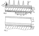
- the support (10) of integrated circuit devices such as the device (11), according to the invention comprises a removable cooling device (12) shown by way of example in the form of a metal finned radiator in FIG. 1.
- the support (10) illustrated is formed from a substrate (13), in alumina for example, having, on the one hand, a support face (13a) of a metallic multilayer interconnection network (14) (three metallic layers being represented) on which the devices such as (11) are fixed by their lugs (lla) to the corresponding studs (14a) of the network (14) and by their non-active face by means of a layer of adhesive (15) and, on the other hand, a dissipation face (13b) intended to cooperate with the cooling device (12).
- the radiator (12) was directly bonded to the dissipation face (13b) of the substrate (13).
- the radiator (12) made of aluminum for example, is removably mounted on the support (10), by means of a removable fixing means essentially comprising a sheet ( 16) fixed to the dissipation face (13b) of the support (10) and having a coefficient of expansion close to that of the material constituting the substrate (13).
- a removable fixing means essentially comprising a sheet ( 16) fixed to the dissipation face (13b) of the support (10) and having a coefficient of expansion close to that of the material constituting the substrate (13).
- the latter being alumina, the sheet (16) will advantageously be in Kovar for example.
- the sheet (16) is fixed to the substrate (13) by a fixing layer (17).
- This layer can be formed of an epoxy adhesive at low polymerization temperature, of the order of 150 ° C. for example, or of solder such as for example a tin-lead alloy which has the advantage of solidifying at temperature.
- sheet (16) has 250 ? m thick, and the layer (17), from 100 to 200pm. In this way, the sheet (16) is flexible and can thus conform to the shape of the dissipation face (13b) of the substrate.
- threaded rods such as the rod (18) are fixed by welding or gluing to the sheet (16) normally at the plane of the latter, while the radiator (12) comprises corresponding openings (19) for cooperating with the rods (18) and being fixed to these rods by means of nuts (20).
- a good heat conducting foam (21) can be interposed between the radiator (12) and the sheet (16), in order to ensure a good thermal bond between the sheet (16) and the radiator (12) despite the flatness defects that may exist between these two metallic elements.
- the foam (21) may be a silicone foam loaded with alumina or silver, with a thickness of the order of 300 to 500 ⁇ m.
- the desoldering of the tabs (IIa) on the studs (14a) of the interconnection network (14) and the takeoff of the device from the layer (15) are easily practiced when one wants to replace a faulty device (11), and the installation of the new device is also easy and reliable.
- the invention may include several variants.
- the magnetic properties of the Kovar are used to directly fix the cooling device (12) by magnetic attraction against the sheet (16), for example by suitably magnetizing the face of the cooling device which is in contact with the sheet (16).
- the cooling device (12) shown in FIG. 2 is not a radiator, but an element with cooling channels (22) by circulation of a cooling fluid in these channels, delimited by walls ( 23).
- the coolant can be water.
- the wall (23) intended to come into contact with the sheet (16) is magnetizable or magnetized suitably to ensure the desired attachment of the cooling device (12) to the sheet (16).
Landscapes
- Cooling Or The Like Of Semiconductors Or Solid State Devices (AREA)
- Cooling Or The Like Of Electrical Apparatus (AREA)
Applications Claiming Priority (2)
| Application Number | Priority Date | Filing Date | Title |
|---|---|---|---|
| FR8025857 | 1980-12-05 | ||
| FR8025857A FR2495838A1 (fr) | 1980-12-05 | 1980-12-05 | Dispositif de refroidissement amovible pour supports de circuits integres |
Publications (1)
| Publication Number | Publication Date |
|---|---|
| EP0053967A1 true EP0053967A1 (de) | 1982-06-16 |
Family
ID=9248715
Family Applications (1)
| Application Number | Title | Priority Date | Filing Date |
|---|---|---|---|
| EP81401869A Withdrawn EP0053967A1 (de) | 1980-12-05 | 1981-11-25 | Abnehmbare Kühlanordnung für integrierte Schaltungsträger |
Country Status (3)
| Country | Link |
|---|---|
| EP (1) | EP0053967A1 (de) |
| JP (1) | JPS57120359A (de) |
| FR (1) | FR2495838A1 (de) |
Cited By (4)
| Publication number | Priority date | Publication date | Assignee | Title |
|---|---|---|---|---|
| DE3531729A1 (de) * | 1984-10-11 | 1986-04-17 | Teradyne Inc., Boston, Mass. | Waermeableitvorrichtung fuer elektronik-bauteile auf keramiksubstrat |
| EP0241290A1 (de) * | 1986-04-09 | 1987-10-14 | Nec Corporation | Kühlungssystem für elektronische Bauelemente |
| GB2198888A (en) * | 1986-12-09 | 1988-06-22 | Lucas Ind Plc | Cooling electronic components |
| WO1998028961A1 (de) * | 1996-12-20 | 1998-07-02 | Magnet-Motor Gesellschaft Für Magnetmotorische Technik Mbh | Bauelementträger mit luft-umwälzkühlung der elektrischen bauelemente |
Families Citing this family (1)
| Publication number | Priority date | Publication date | Assignee | Title |
|---|---|---|---|---|
| JPH0760953B2 (ja) * | 1985-07-26 | 1995-06-28 | 富士通株式会社 | 誘電体基板の接着方法 |
Citations (4)
| Publication number | Priority date | Publication date | Assignee | Title |
|---|---|---|---|---|
| GB881571A (en) * | 1958-09-25 | 1961-11-08 | Stone J & Co Ltd | Improvements relating to the cooling of semi-conductor devices |
| FR2236272A1 (en) * | 1973-07-06 | 1975-01-31 | Siemens Ag | Power semiconductor metal heat sink - uses intermediate metal block for semiconductor and heat sink connection |
| US4025997A (en) * | 1975-12-23 | 1977-05-31 | International Telephone & Telegraph Corporation | Ceramic mounting and heat sink device |
| EP0000856A1 (de) * | 1977-08-12 | 1979-02-21 | International Business Machines Corporation | Magnetische Wärmeleitungsanordnung für Halbleiterplättchen |
Family Cites Families (2)
| Publication number | Priority date | Publication date | Assignee | Title |
|---|---|---|---|---|
| DE2638909A1 (de) * | 1976-08-28 | 1978-03-02 | Semikron Gleichrichterbau | Halbleiteranordnung |
| US4278990A (en) * | 1979-03-19 | 1981-07-14 | General Electric Company | Low thermal resistance, low stress semiconductor package |
-
1980
- 1980-12-05 FR FR8025857A patent/FR2495838A1/fr not_active Withdrawn
-
1981
- 1981-11-25 EP EP81401869A patent/EP0053967A1/de not_active Withdrawn
- 1981-12-04 JP JP56194637A patent/JPS57120359A/ja active Pending
Patent Citations (4)
| Publication number | Priority date | Publication date | Assignee | Title |
|---|---|---|---|---|
| GB881571A (en) * | 1958-09-25 | 1961-11-08 | Stone J & Co Ltd | Improvements relating to the cooling of semi-conductor devices |
| FR2236272A1 (en) * | 1973-07-06 | 1975-01-31 | Siemens Ag | Power semiconductor metal heat sink - uses intermediate metal block for semiconductor and heat sink connection |
| US4025997A (en) * | 1975-12-23 | 1977-05-31 | International Telephone & Telegraph Corporation | Ceramic mounting and heat sink device |
| EP0000856A1 (de) * | 1977-08-12 | 1979-02-21 | International Business Machines Corporation | Magnetische Wärmeleitungsanordnung für Halbleiterplättchen |
Non-Patent Citations (1)
| Title |
|---|
| IBM Technical Disclosure Bulletin, Vol. 21, No. 3, Aout 1978 New York, US R.D. DURAND et al.: "Ceramic Cap and Heat Sink for Semiconductor Package", pages 1064-1065 * figure 2; page 1065, alinea 2 * * |
Cited By (4)
| Publication number | Priority date | Publication date | Assignee | Title |
|---|---|---|---|---|
| DE3531729A1 (de) * | 1984-10-11 | 1986-04-17 | Teradyne Inc., Boston, Mass. | Waermeableitvorrichtung fuer elektronik-bauteile auf keramiksubstrat |
| EP0241290A1 (de) * | 1986-04-09 | 1987-10-14 | Nec Corporation | Kühlungssystem für elektronische Bauelemente |
| GB2198888A (en) * | 1986-12-09 | 1988-06-22 | Lucas Ind Plc | Cooling electronic components |
| WO1998028961A1 (de) * | 1996-12-20 | 1998-07-02 | Magnet-Motor Gesellschaft Für Magnetmotorische Technik Mbh | Bauelementträger mit luft-umwälzkühlung der elektrischen bauelemente |
Also Published As
| Publication number | Publication date |
|---|---|
| FR2495838A1 (fr) | 1982-06-11 |
| JPS57120359A (en) | 1982-07-27 |
Similar Documents
| Publication | Publication Date | Title |
|---|---|---|
| EP0308296B1 (de) | Mit einer Wärmeabfuhrvorrichtung versehene gedruckte Schaltung | |
| JPH07502141A (ja) | めっきしたしなやかなリード線 | |
| US20030226688A1 (en) | Vented circuit board for cooling power components | |
| FR2550905A1 (fr) | Carte de circuit imprime | |
| EP0749160A1 (de) | Verfahren zum Kühlen einer in einem Gehäuse montierten integrierten Schaltung | |
| EP0055640B1 (de) | Klemmanordnung für aufeinandergelegte Elemente ausgerichteter Gruppen, insbesondere für die elektrische Verbindung leitender Elemente | |
| EP1047294A1 (de) | Isoliertes metallisches Substrat für Leiterplatten | |
| JP4117807B2 (ja) | 電子部品のハンダ付け方法 | |
| EP1005083B1 (de) | Elektronisches Leistungselement mit Kühlvorrichtung | |
| JP2000058930A (ja) | 熱電素子およびその製造方法 | |
| EP0717442B1 (de) | Träger für integrierten Schaltkreis zur Kontaktierung eines anderen Trägers mittels Kontaktkugeln | |
| EP0053967A1 (de) | Abnehmbare Kühlanordnung für integrierte Schaltungsträger | |
| US6671176B1 (en) | Method of cooling heat-generating electrical components | |
| EP0779775B1 (de) | Elektronische Baugruppe mit Wärmeabführung, besonders für Hochspannungsumwandler einer Entladungslampe von Scheinwerfer | |
| EP1116424B1 (de) | Elektronische baugruppe mit einer wärmeplatte | |
| FR2793990A1 (fr) | Boitier electronique sur plaque et procede de fabrication d'un tel boitier | |
| WO1993013556A1 (fr) | Systeme de refroidissement pour module 'multi-puces' | |
| EP1035573A1 (de) | Elektrisches Leistungsbauelement auf einen Träger gelötet und Montierungsverfahren dafür | |
| FR2571921A1 (fr) | Dissipateur de chaleur pour composants electroniques avec substrat en ceramique | |
| FR2523397A1 (fr) | Procede de montage de composants electroniques sur un support et produit realisable par le procede | |
| EP0093659A1 (de) | Träger für integrierte Schaltungsanordnungen | |
| US20050284607A1 (en) | Cooling-assisted, heat-generating electrical component and method of manufacturing same | |
| JP2798464B2 (ja) | 電力増幅モジュール構造 | |
| EP0680248B1 (de) | Verfahren zur Herstellung einer elektronischen Leistungsschaltung und nach diesem Verfahren erhaltene elektronische Schaltung | |
| FR2716302A1 (fr) | Dispositif de chauffage pour la réalisation de connexions par un matériau fusible. |
Legal Events
| Date | Code | Title | Description |
|---|---|---|---|
| PUAI | Public reference made under article 153(3) epc to a published international application that has entered the european phase |
Free format text: ORIGINAL CODE: 0009012 |
|
| AK | Designated contracting states |
Designated state(s): CH DE FR GB IT NL |
|
| 17P | Request for examination filed |
Effective date: 19820908 |
|
| STAA | Information on the status of an ep patent application or granted ep patent |
Free format text: STATUS: THE APPLICATION IS DEEMED TO BE WITHDRAWN |
|
| 18D | Application deemed to be withdrawn |
Effective date: 19840103 |
|
| RIN1 | Information on inventor provided before grant (corrected) |
Inventor name: DEHAINE, GERARD |