EP0054301A1 - Dispositif d'allumage pour lampe à décharge à basse pression - Google Patents
Dispositif d'allumage pour lampe à décharge à basse pression Download PDFInfo
- Publication number
- EP0054301A1 EP0054301A1 EP81110450A EP81110450A EP0054301A1 EP 0054301 A1 EP0054301 A1 EP 0054301A1 EP 81110450 A EP81110450 A EP 81110450A EP 81110450 A EP81110450 A EP 81110450A EP 0054301 A1 EP0054301 A1 EP 0054301A1
- Authority
- EP
- European Patent Office
- Prior art keywords
- branch
- voltage divider
- ignition device
- resistor
- parallel
- Prior art date
- Legal status (The legal status is an assumption and is not a legal conclusion. Google has not performed a legal analysis and makes no representation as to the accuracy of the status listed.)
- Granted
Links
Images

Classifications
-
- H—ELECTRICITY
- H05—ELECTRIC TECHNIQUES NOT OTHERWISE PROVIDED FOR
- H05B—ELECTRIC HEATING; ELECTRIC LIGHT SOURCES NOT OTHERWISE PROVIDED FOR; CIRCUIT ARRANGEMENTS FOR ELECTRIC LIGHT SOURCES, IN GENERAL
- H05B41/00—Circuit arrangements or apparatus for igniting or operating discharge lamps
- H05B41/02—Details
- H05B41/04—Starting switches
- H05B41/042—Starting switches using semiconductor devices
- H05B41/044—Starting switches using semiconductor devices for lamp provided with pre-heating electrodes
- H05B41/046—Starting switches using semiconductor devices for lamp provided with pre-heating electrodes using controlled semiconductor devices
-
- Y—GENERAL TAGGING OF NEW TECHNOLOGICAL DEVELOPMENTS; GENERAL TAGGING OF CROSS-SECTIONAL TECHNOLOGIES SPANNING OVER SEVERAL SECTIONS OF THE IPC; TECHNICAL SUBJECTS COVERED BY FORMER USPC CROSS-REFERENCE ART COLLECTIONS [XRACs] AND DIGESTS
- Y10—TECHNICAL SUBJECTS COVERED BY FORMER USPC
- Y10S—TECHNICAL SUBJECTS COVERED BY FORMER USPC CROSS-REFERENCE ART COLLECTIONS [XRACs] AND DIGESTS
- Y10S315/00—Electric lamp and discharge devices: systems
- Y10S315/05—Starting and operating circuit for fluorescent lamp
Definitions
- the invention relates to an ignition device for a low-pressure discharge lamp, in which a triac is connected in parallel to the low-pressure discharge lamp and in series with the heating electrodes.
- the triac is connected with its control connection via a diac to the connection point of a voltage divider, which is also connected in parallel to the low-pressure discharge lamp and whose first branch is a fixed resistor contains and the other branch is formed by a capacitor.
- the circuit variants of FIGS. 2, 3 and 4 all have a voltage divider parallel to the connections A 'and 8' of the triac 10.
- the second connection of the diac 11 arranged in the control circuit of the triac taps off the voltage drop across the capacitor 12, which forms the second branch of the voltage divider.
- the variants are in the first branch of the voltage divider, with certain properties of the ignition device being intended to be achieved by connecting different functional groups in series.
- the capacitor 14 as explained in detail in the above-mentioned document, has a special meaning: In order to prevent the ignition process of the already ignited low-pressure discharge lamp from being repeated, the capacitor 14 must be dimensioned very narrowly so that the ignition voltage of the slide 11 is not reached when the low-pressure discharge lamp has an operating voltage.
- the capacitor 14 responsible for switching off the ignition pulses is bridged by a resistor 18, as a result of which the switch-off effect of the capacitor is further critically influenced.
- a diode 17 is connected in parallel with the resistor 13 in FIG. 4, which results when an inductive ballast is used an asymmetrical loading of the inductor 4 ( Figure 6) and thus an increased preheating current of the electrode coils 2 and 3 results.
- a certain countercurrent flows through the resistor 13, which in turn causes a certain magnetic reversal of the inductor 4 and reduces the preheating current.
- the object of the invention is to provide an ignition device with which a low-pressure discharge lamp is gently ignited with good and rapid preheating of the electrode filaments. After the lamp has ignited, further attempts to ignite the ignition device are to be prevented with certainty.
- the ignition device should also be used under different operating conditions, e.g. at different outside temperatures or different ballasts of the low-pressure discharge lamp.
- the ignition device with the features mentioned in the preamble of the main claim is characterized in that the first branch of the voltage divider also contains at least one variable resistor and further parts of the first branch of the voltage divider and the second branch of the voltage divider are bridged by an additional variable resistor.
- the first branch of the voltage divider contains a first variable resistor, which forms a series circuit with the fixed resistor and one connection of which is connected to the triac.
- the additional variable resistance also bridges the fixed resistor from the first branch of the voltage divider.
- Such a circuit arrangement is particularly suitable, for example, for compact, low-pressure discharge lamps with short discharge arcs and operating voltages of less than 60 V, the ballast preferably consisting of a series connection of an ohmic resistor and a capacitor.
- a parallel connection of a second variable resistor and a diode is connected in series with the first branch of the voltage divider, one connection of which is connected to the diac.
- the ballast consists of a choke or a choke with a series capacitor.
- the diode causes a very high preheating current and the thermistor connected in parallel leads the preheating current back to normal values after the lamp has been ignited.
- the first variable resistor in the first branch of the voltage divider is a frequency-dependent resistor which has a low resistance during the preheating of the electrode filaments and a high resistance after the low-pressure discharge lamp has been ignited.
- the frequency-dependent resistor can be replaced by a voltage-dependent resistor in a further circuit configuration.
- the additional variable resistor bridging the capacitor of the second branch and part of the first branch is advantageously connected between the parallel circuit consisting of diode and second variable resistor and the fixed resistor.
- the second variable resistor in the first branch of the voltage divider and the variable resistor bridging the capacitor of the second branch and part of the first branch is in each case a temperature-dependent resistor with a negative temperature coefficient. Their functions will be explained in more detail later.
- An interference suppression capacitor is connected in parallel with the triac.
- the interference suppression capacitor is designed as a capacitive voltage divider, a self-switching four-layer diode being connected to the center of the same, the other connection of which is led to one of the end points of the voltage divider.
- Short ignition times can be achieved with the ignition device for low-pressure discharge lamps according to the invention.
- the electrode coils are preheated well by first applying low peak values and increasing each period to avoid cold ignitions, until the ignition occurs safely, which is decisive for the lamp life. If the lamp is non-igniting, the preheating current is switched off within approx. One second and further ignition attempts are prevented, which protects the ballast and the lamp.
- the ignition device can be adapted to a variety of ballasts and low-pressure discharge lamps with different ignition voltages with only a few minor extensions or modifications.
- the few electronic components can easily be installed in a conventional housing for starters or can be arranged - with or without ballast - within the lamp itself, making the ignition device also suitable for compact low-pressure discharge lamps.
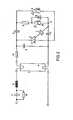
- a triac 2 is connected in parallel to a fluorescent lamp 1, the control connection of which is connected via a diac 3 to a connection point 4 of a voltage divider which is also connected in parallel with the fluorescent lamp 1.
- the voltage divider has two branches, the first branch of which is a series connection of a La dewistores 5 and a frequency-dependent resistor in the form of a control capacitor 6 and the other branch is formed by a trigger capacitor 7.
- the trigger capacitor 7 and the charging resistor 5 are bridged by a cut-off thermistor 8.
- An interference suppression capacitor 9 is also connected in parallel with the triac 2.
- a fuse resistor 10 is arranged in one of the leads of the ignition device.
- the ballast for limiting the current of the fluorescent lamp 1 is formed by the series connection of an operating capacitor 11 and a damping resistor 12.
- a discharge resistor 13 is connected in parallel with the operating capacitor 11.
- the function of the ignition device is to be described in the following way.
- the trigger capacitor 7 is charged via the charging resistor 5 and additionally via the control capacitor 6.
- the triac 2 is controlled via the diac 3 by partially discharging the trigger capacitor 7, the size of the charging resistor 5 determining the charging time of the trigger capacitor 7 and thus the moment when the triac 2 is switched through.
- the charging time of the trigger capacitor 7 is also influenced by the shutdown thermistor 8.
- the shutdown thermistor 8 has two tasks: Firstly, the moment of switching of the triac 2 is changed by its change in resistance. This results in the possibility of providing a small peak value when the mains voltage is applied in order to avoid cold ignition of the fluorescent lamp 1 and then to increase it after the lamp electrodes have already been heated so that the ignition takes place safely.
- the shutdown thermistor 8 is designed such that it switches off the preheating current within one second if the fluorescent lamp 1 does not ignite due to its reduction in resistance.
- the shutdown thermistor 8 is heated with the aid of the control capacitor 6.
- the frequency-dependent resistance of capacitors is used. As long as the preheating current flows through the electrode filaments of the fluorescent lamp 1, narrow voltage pulses of higher frequency result. The low resistance of the control capacitor 6 at a higher frequency results in a rapid heating of the shutdown thermistor 8.
- the ignition device After switching off the preheating current if the fluorescent lamp does not ignite - e.g. at the end of the lamp life - the 50 Hz mains voltage is at the control capacitor 6. This is dimensioned so that the current flowing through it is sufficient to keep the heated shutdown thermistor 8 low. After switching off the mains voltage and cooling of the shutdown thermistor 8, the ignition device becomes functional again.
- Another advantage of this ignition device is that the half-wave operation of fluorescent lamps at the end of their service life is prevented in circuits according to FIG. 1 by the cut-off thermistor 8, in that the latter is heated so that the triac 2 is blocked.
- the same ignition device can be used.
- the ignition device can also be expanded to a quick start ignition device with a slight extension.
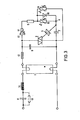
- the parallel connection of a bridging hot conductor 15 and a diode 16 is additionally connected in series between the connection point 4 and the charging resistor 5, the polarity of the diode 16 being arbitrary.
- the diode causes the triac 2 to be actuated on one side and thus a greatly increased preheating current of the electrode filaments.
- the bridging hot conductor 15 leads the excessive preheating current back to normal values within half a second. It also enables normal preheating of the electrode coils in capacitive ballasts.
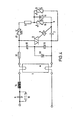
- control capacitor can also be replaced by a voltage-dependent resistor 17. Its size is selected so that on the one hand a reliable response of the ignition device before the lamp ignition is guaranteed and on the other hand the ignition device remains switched off after the lamp ignition.
- the connection of the shutdown thermistor 8 is in this case between the charging resistor 5 and the over bridging hot conductor 15 and diode 16 arranged parallel circuit, whereby an overload of the bridging hot conductor 15 after changing to low resistance values is avoided in a simple manner.
- the level of the voltage available for lamp ignition in inductive and capacitive ballasts in the circuit examples of FIGS. 2 and 3 depends only on the capacitance of the interference suppression capacitor 9. With a capacity of e.g. ⁇ 10 nF the peak value of the mains voltage is reached. If the capacitance of the interference suppression capacitor is e.g. 47 nF increases, the peak value of the open circuit voltage is approx. 400 V, which is sufficient for the ignition of lamps that ignite normally.
- the circuit according to FIGS. 4 or 5 must be expanded for fluorescent lamps which are difficult to ignite.
- the interference suppression capacitor is designed as a capacitive voltage divider and consists of the partial capacitors 18 and 19. At the center of this voltage divider, a self-switching four-layer diode 20 is connected, the other connection of which is connected to any end point of the voltage divider. With such a circuit arrangement according to FIG. 4, peak values of around 600 V can be achieved.
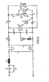
- Voltages with peak values around 800 V are e.g. achievable with a circuit according to FIG. 5.
- a small inductance 21 is connected in series with the self-switching four-layer diode 20, which enables the partial capacitor 19 assigned to it to be recharged.
Landscapes
- Circuit Arrangements For Discharge Lamps (AREA)
Applications Claiming Priority (2)
| Application Number | Priority Date | Filing Date | Title |
|---|---|---|---|
| DE19803047289 DE3047289A1 (de) | 1980-12-16 | 1980-12-16 | Zuendvorrichtung fuer eine niederdruckentladungslampe |
| DE3047289 | 1980-12-16 |
Publications (2)
| Publication Number | Publication Date |
|---|---|
| EP0054301A1 true EP0054301A1 (fr) | 1982-06-23 |
| EP0054301B1 EP0054301B1 (fr) | 1986-02-19 |
Family
ID=6119254
Family Applications (1)
| Application Number | Title | Priority Date | Filing Date |
|---|---|---|---|
| EP81110450A Expired EP0054301B1 (fr) | 1980-12-16 | 1981-12-15 | Dispositif d'allumage pour lampe à décharge à basse pression |
Country Status (4)
| Country | Link |
|---|---|
| US (1) | US4460848A (fr) |
| EP (1) | EP0054301B1 (fr) |
| JP (1) | JPS57124895A (fr) |
| DE (2) | DE3047289A1 (fr) |
Cited By (3)
| Publication number | Priority date | Publication date | Assignee | Title |
|---|---|---|---|---|
| DE3603084A1 (de) * | 1986-02-01 | 1987-08-06 | Korte Licht | Schaltung zum betrieb einer leuchtstofflampe |
| WO1996022007A1 (fr) * | 1995-01-13 | 1996-07-18 | Yeong Choon Chung | Demarreur electronique pour lampe fluorescente |
| EP0750447A1 (fr) * | 1995-06-22 | 1996-12-27 | ECKERLE INDUSTRIE-ELEKTRONIK GmbH | Circuit pour allumer une lampe fluorescente |
Families Citing this family (11)
| Publication number | Priority date | Publication date | Assignee | Title |
|---|---|---|---|---|
| DE3311215A1 (de) * | 1983-03-28 | 1984-10-04 | Patent-Treuhand-Gesellschaft für elektrische Glühlampen mbH, 8000 München | Zuendvorrichtung fuer eine niederdruckentladungslampe |
| JPS60102875A (ja) * | 1983-11-09 | 1985-06-07 | Toichi Chikuma | 位相制御装置 |
| DE3417794A1 (de) * | 1984-05-14 | 1985-11-14 | Philips Patentverwaltung Gmbh, 2000 Hamburg | Schaltungsanordnung zur regelung der brennspannung von hochdruckgasentladungslampen |
| US4649319A (en) * | 1984-10-03 | 1987-03-10 | Duro-Test Corporation | Gas discharge lamp starter |
| US4777410A (en) * | 1987-06-22 | 1988-10-11 | Innovative Controls, Inc. | Ballast striker circuit |
| US4866347A (en) * | 1987-09-28 | 1989-09-12 | Hubbell Incorporated | Compact fluorescent lamp circuit |
| US4900986A (en) * | 1988-09-06 | 1990-02-13 | General Electric Company | Ballast circuit for starting fluorescent lamps |
| US5023521A (en) * | 1989-12-18 | 1991-06-11 | Radionic Industries, Inc. | Lamp ballast system |
| US5387849A (en) * | 1992-12-14 | 1995-02-07 | Radionic Technology Incorporated | Lamp ballast system characterized by a power factor correction of greater than or equal to 90% |
| US5736817A (en) * | 1995-09-19 | 1998-04-07 | Beacon Light Products, Inc. | Preheating and starting circuit and method for a fluorescent lamp |
| CA2300351A1 (fr) * | 1999-04-21 | 2000-10-21 | Eric Ngo | Ballast de lampe fluorescente avec demarreur electronique et condensateur resonant de reduction du courant d'entree |
Citations (2)
| Publication number | Priority date | Publication date | Assignee | Title |
|---|---|---|---|---|
| DE2034855A1 (de) * | 1970-07-07 | 1972-01-27 | Luehrs O | Elektronische Zündeinrichtung fur Niederdruck Gasentladungslampen |
| GB2024545A (en) * | 1978-06-27 | 1980-01-09 | Philips Nv | Gas and/or vapour discharge tube circuits |
Family Cites Families (3)
| Publication number | Priority date | Publication date | Assignee | Title |
|---|---|---|---|---|
| NL6815032A (fr) * | 1968-10-21 | 1970-04-23 | ||
| FR2223932B1 (fr) * | 1973-03-30 | 1978-03-10 | Radiotechnique Compelec | |
| DE2924069C2 (de) * | 1979-06-15 | 1982-05-13 | Philips Patentverwaltung Gmbh, 2000 Hamburg | Schaltungsanordnung zum Zünden und Betrieb einer Gas- und/oder Dampfentladungslampe |
-
1980
- 1980-12-16 DE DE19803047289 patent/DE3047289A1/de not_active Withdrawn
-
1981
- 1981-12-02 US US06/326,498 patent/US4460848A/en not_active Expired - Fee Related
- 1981-12-15 EP EP81110450A patent/EP0054301B1/fr not_active Expired
- 1981-12-15 DE DE8181110450T patent/DE3173854D1/de not_active Expired
- 1981-12-16 JP JP56203324A patent/JPS57124895A/ja active Pending
Patent Citations (2)
| Publication number | Priority date | Publication date | Assignee | Title |
|---|---|---|---|---|
| DE2034855A1 (de) * | 1970-07-07 | 1972-01-27 | Luehrs O | Elektronische Zündeinrichtung fur Niederdruck Gasentladungslampen |
| GB2024545A (en) * | 1978-06-27 | 1980-01-09 | Philips Nv | Gas and/or vapour discharge tube circuits |
Cited By (3)
| Publication number | Priority date | Publication date | Assignee | Title |
|---|---|---|---|---|
| DE3603084A1 (de) * | 1986-02-01 | 1987-08-06 | Korte Licht | Schaltung zum betrieb einer leuchtstofflampe |
| WO1996022007A1 (fr) * | 1995-01-13 | 1996-07-18 | Yeong Choon Chung | Demarreur electronique pour lampe fluorescente |
| EP0750447A1 (fr) * | 1995-06-22 | 1996-12-27 | ECKERLE INDUSTRIE-ELEKTRONIK GmbH | Circuit pour allumer une lampe fluorescente |
Also Published As
| Publication number | Publication date |
|---|---|
| JPS57124895A (en) | 1982-08-03 |
| DE3047289A1 (de) | 1982-07-29 |
| DE3173854D1 (en) | 1986-03-27 |
| US4460848A (en) | 1984-07-17 |
| EP0054301B1 (fr) | 1986-02-19 |
Similar Documents
| Publication | Publication Date | Title |
|---|---|---|
| EP0185179B1 (fr) | Circuit d'allumage pour une lampe à décharge à basse pression | |
| EP0120405B1 (fr) | Dispositif d'allumage pour lampe de décharge à basse pression | |
| EP0054301B1 (fr) | Dispositif d'allumage pour lampe à décharge à basse pression | |
| DE3108548C2 (de) | Zündschaltung für eine Hochdruckmetalldampfentladungslampe | |
| DE2116950C3 (de) | Schaltungsanordnung zum Zünden und zum Betrieb von Gasentladungslampen | |
| EP0693864B1 (fr) | Circuit pour alimenter une ou plusieurs lampes à décharge basse-pression | |
| DE2751464A1 (de) | Starter zum zuenden einer gas- und/oder dampfentladungslampe | |
| EP0471332A1 (fr) | Assemblage de circuit pour le fonctionnement d'une lampe fluorescente | |
| DE3046617C2 (fr) | ||
| DE3883042T2 (de) | Einrichtung zum Ermöglichen der Wiederherstellung des Stroms einer Leitung im Falle des Durchschlagens eines oder mehrerer Elemente einer Serienschaltung. | |
| DE69513646T2 (de) | Schaltung zum Betreiben von Entladungslampen mit vorgeheizten Wendeln | |
| DE2802218A1 (de) | Elektronischer starter zum zuenden einer entladungslampe | |
| DE69616451T2 (de) | Umschaltanordnung | |
| DE2639475A1 (de) | Entladungslampe | |
| DE1952697B2 (de) | Vorrichtung zur elektronischen zuendung von gasentladungslampen | |
| DE2445032C2 (de) | Schaltungsanordnung zur Erzeugung einer Einschaltspannung für den Steuerteil eines Mittelfrequenz-Umrichters | |
| EP0534280A1 (fr) | Ballast pour faire démarrer et mettre en service des lampes de décharge à gaz à haute pression | |
| EP0252438B1 (fr) | Dispositif d'allumage pour lampes à décharge à haute pression | |
| DE10252836A1 (de) | Vorrichtung zum Betreiben von Entlaudungslampen | |
| EP0519220A1 (fr) | Ballast avec temps de chauffage commandé | |
| DE3208607C2 (fr) | ||
| EP0069967B1 (fr) | Dispositif pour allumer des lampes fluorescentes | |
| DE2425720A1 (de) | Vorschaltgeraet fuer entladungslampen | |
| DE2604914C3 (de) | Schaltungsanordnung zum Zünden und zum Betrieb einer Entladungslampe | |
| EP1377136A2 (fr) | Dispositif pour alimenter des lampes à décharge |
Legal Events
| Date | Code | Title | Description |
|---|---|---|---|
| PUAI | Public reference made under article 153(3) epc to a published international application that has entered the european phase |
Free format text: ORIGINAL CODE: 0009012 |
|
| AK | Designated contracting states |
Designated state(s): CH DE FR GB IT |
|
| 17P | Request for examination filed |
Effective date: 19821208 |
|
| ITF | It: translation for a ep patent filed | ||
| GRAA | (expected) grant |
Free format text: ORIGINAL CODE: 0009210 |
|
| AK | Designated contracting states |
Designated state(s): CH DE FR GB IT LI |
|
| ET | Fr: translation filed | ||
| REF | Corresponds to: |
Ref document number: 3173854 Country of ref document: DE Date of ref document: 19860327 |
|
| PLBE | No opposition filed within time limit |
Free format text: ORIGINAL CODE: 0009261 |
|
| STAA | Information on the status of an ep patent application or granted ep patent |
Free format text: STATUS: NO OPPOSITION FILED WITHIN TIME LIMIT |
|
| 26N | No opposition filed | ||
| PG25 | Lapsed in a contracting state [announced via postgrant information from national office to epo] |
Ref country code: GB Effective date: 19881215 |
|
| PG25 | Lapsed in a contracting state [announced via postgrant information from national office to epo] |
Ref country code: LI Effective date: 19881231 Ref country code: CH Effective date: 19881231 |
|
| GBPC | Gb: european patent ceased through non-payment of renewal fee | ||
| PG25 | Lapsed in a contracting state [announced via postgrant information from national office to epo] |
Ref country code: FR Free format text: LAPSE BECAUSE OF NON-PAYMENT OF DUE FEES Effective date: 19890831 |
|
| REG | Reference to a national code |
Ref country code: CH Ref legal event code: PL |
|
| PG25 | Lapsed in a contracting state [announced via postgrant information from national office to epo] |
Ref country code: DE Effective date: 19890901 |
|
| REG | Reference to a national code |
Ref country code: FR Ref legal event code: ST |