EP0120405B1 - Dispositif d'allumage pour lampe de décharge à basse pression - Google Patents
Dispositif d'allumage pour lampe de décharge à basse pression Download PDFInfo
- Publication number
- EP0120405B1 EP0120405B1 EP84102749A EP84102749A EP0120405B1 EP 0120405 B1 EP0120405 B1 EP 0120405B1 EP 84102749 A EP84102749 A EP 84102749A EP 84102749 A EP84102749 A EP 84102749A EP 0120405 B1 EP0120405 B1 EP 0120405B1
- Authority
- EP
- European Patent Office
- Prior art keywords
- capacitor
- trigger
- triac
- voltage divider
- circuit
- Prior art date
- Legal status (The legal status is an assumption and is not a legal conclusion. Google has not performed a legal analysis and makes no representation as to the accuracy of the status listed.)
- Expired
Links
- 239000003990 capacitor Substances 0.000 claims abstract description 39
- 230000010287 polarization Effects 0.000 claims 1
- 230000001419 dependent effect Effects 0.000 description 3
- 238000000034 method Methods 0.000 description 2
- 230000001629 suppression Effects 0.000 description 2
- 230000033228 biological regulation Effects 0.000 description 1
- 238000005265 energy consumption Methods 0.000 description 1
- 230000002349 favourable effect Effects 0.000 description 1
- 230000001939 inductive effect Effects 0.000 description 1
- 238000004519 manufacturing process Methods 0.000 description 1
- 230000033764 rhythmic process Effects 0.000 description 1
Images
Classifications
-
- H—ELECTRICITY
- H05—ELECTRIC TECHNIQUES NOT OTHERWISE PROVIDED FOR
- H05B—ELECTRIC HEATING; ELECTRIC LIGHT SOURCES NOT OTHERWISE PROVIDED FOR; CIRCUIT ARRANGEMENTS FOR ELECTRIC LIGHT SOURCES, IN GENERAL
- H05B41/00—Circuit arrangements or apparatus for igniting or operating discharge lamps
- H05B41/02—Details
- H05B41/04—Starting switches
- H05B41/042—Starting switches using semiconductor devices
- H05B41/044—Starting switches using semiconductor devices for lamp provided with pre-heating electrodes
- H05B41/046—Starting switches using semiconductor devices for lamp provided with pre-heating electrodes using controlled semiconductor devices
-
- Y—GENERAL TAGGING OF NEW TECHNOLOGICAL DEVELOPMENTS; GENERAL TAGGING OF CROSS-SECTIONAL TECHNOLOGIES SPANNING OVER SEVERAL SECTIONS OF THE IPC; TECHNICAL SUBJECTS COVERED BY FORMER USPC CROSS-REFERENCE ART COLLECTIONS [XRACs] AND DIGESTS
- Y02—TECHNOLOGIES OR APPLICATIONS FOR MITIGATION OR ADAPTATION AGAINST CLIMATE CHANGE
- Y02B—CLIMATE CHANGE MITIGATION TECHNOLOGIES RELATED TO BUILDINGS, e.g. HOUSING, HOUSE APPLIANCES OR RELATED END-USER APPLICATIONS
- Y02B20/00—Energy efficient lighting technologies, e.g. halogen lamps or gas discharge lamps
Definitions
- the invention relates to an ignition device for a low-pressure discharge lamp, in which a triac is connected in parallel to the lamp and in series with the preheatable electrodes, the control electrode connection of which is led to the center tap of a voltage divider also running parallel to the lamp via a diac and a charging resistor in series therewith , and the diac is also connected to the main electrode connection of the triac via a trigger capacitor.
- the circuit arrangement above is a circuit for phase gating control, the voltage divider usually consisting of an adjustable resistor and a capacitor. Such a basic circuit is used in variously modified forms for controlling household and industrial devices.
- this circuit arrangement In DE-OS 3 047 289, a modified form of this basic circuit is used to ignite low-pressure discharge lamps with low starting voltages.
- this circuit arrangement also has a variable resistor in the voltage divider. The latter is used to heat a shutdown thermistor (this is arranged parallel to the charging resistor and the trigger capacitor) and thus supports its mode of operation.
- the variable resistance can e.g. a control capacitor (frequency dependent) or a voltage dependent resistor.
- an interference suppression capacitor is connected, which consists of a capacitive voltage divider in a circuit design for fluorescent lamps that are difficult to ignite, one of the capacitors being bridged by a self-switching four-layer diode.
- This circuit is relatively complex in terms of the components used. It also switches off when the low-pressure discharge lamp is not ignited as soon as the voltage has been ramped up, and thus prevents further ignition attempts.
- the object of the invention is to provide an ignition device which can be used to achieve a quick, safe and gentle ignition of low-pressure discharge lamps which are particularly difficult to ignite.
- Discharge lamps that are difficult to ignite include the compact, low-pressure discharge lamps that have been increasingly developed in recent years.
- the ignition device should consist of as few components as possible so that it can be accommodated in the smallest space. In this case, there is the possibility of integrating the circuit in the compact low-pressure discharge lamp.
- the ignition device with the features mentioned in the preamble of the main claim is characterized according to the invention in that the voltage divider is of a capacitive type and consists only of two capacitor blocks of the same size, the capacitance ratio of a capacitor block to the trigger capacitor being between 1: 1 and 1: 5 and that of charging resistance and trigger capacitor existing trigger circuit has a time constant between 1 and 8 ms.
- the respective capacitor block can consist of one or a series connection of several capacitors.
- the same size means that the characteristics of the two capacitor blocks should match. However, the actual capacitance values may have the usual tolerances.
- This circuit design forms an ignition circuit which quickly heats up the electrodes by means of a high preheating current and subsequently ensures reliable ignition by means of high voltage peaks in both directions.
- This circuit of relatively few components continuously repeats the voltage ramp-up. It does not require a four-layer diode in order to achieve higher surge voltages, because it has surprisingly been shown that even with small capacitances (approx. 5 nF) for the voltage divider, this circuit arrangement provides at least 1.4 times the peak value of the supply voltage even with small capacitances can be achieved.
- the capacitance ratio of a voltage divider capacitance to the trigger capacitance between 1: 1 and 1: 5 is necessary in order to achieve the higher surge voltages.
- a capacity ratio of 1: 3 has proven to be favorable.
- the above-mentioned time constant of the trigger circuit guarantees that there is a sufficiently high response voltage or non-reclosing voltage of the triac, as is required to start low-pressure discharge lamps that are difficult to ignite.
- a time constant between 4 and 6 ms has proven to be optimal.
- polarity-dependent lamp ignition can occur in extreme cases. To ensure that this does not happen in any case and that the circuit shows a safe tipping behavior with surge voltages of the same level in both polarities, a parallel circuit consisting of a diode with any forward direction and a resistor is arranged between the diac and the trigger capacitor.
- a high-frequency choke is installed in the main circuit of the ignition device with the triac, which causes a reduction in the current rise speed.
- the main circuit has a PTC thermistor, which interrupts the starting process within 60 s when the lamp is no longer igniting.
- the capacitance of each capacitor block must be between 10 and 40 nF.
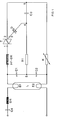
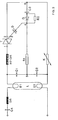
- 1 shows an ignition device for a compact fluorescent lamp L of 16 W with heatable electrodes E1, E2 and a series arrangement of choke DR and possibly capacitor C4, in which a triac T with a peak reverse voltage of 700V is connected in parallel to the lamp L. loadable with a current of 3 A.
- 1, 2 denote the two main electrode connections of the triac T.
- the control electrode connection 3 of the triac T is via a diac D with a breakover voltage of 32 V, a connection point 4 and a charging resistor R1 of 68 K ⁇ to the center tap 5 of a voltage divider, which also runs parallel to the lamp L and consists of two capacitors C1, C2 each of 22 nF guided.
- the diac D is connected to the main electrode terminal 2 of the triac T via the connection point 4, a trigger capacitor C3 of 68 nF and a connection point 6.
- a parallel connection consisting of a diode G and a resistor R2 of 56 ⁇ is used between the connection point 4 and the trigger capacitor C3.
- the forward direction of the diode G is arbitrary.
- the gate angle also changes continuously in a certain rhythm, e.g. with the above characteristics with approx. 3 Hz. Likewise, both the preheating current and the impulse voltage then change, so that the lamps do not ignite automatically.
Landscapes
- Circuit Arrangements For Discharge Lamps (AREA)
Claims (6)
Priority Applications (1)
| Application Number | Priority Date | Filing Date | Title |
|---|---|---|---|
| AT84102749T ATE28021T1 (de) | 1983-03-28 | 1984-03-14 | Zuendvorrichtung fuer eine niederdruckentladungslampe. |
Applications Claiming Priority (2)
| Application Number | Priority Date | Filing Date | Title |
|---|---|---|---|
| DE19833311215 DE3311215A1 (de) | 1983-03-28 | 1983-03-28 | Zuendvorrichtung fuer eine niederdruckentladungslampe |
| DE3311215 | 1983-03-28 |
Publications (2)
| Publication Number | Publication Date |
|---|---|
| EP0120405A1 EP0120405A1 (fr) | 1984-10-03 |
| EP0120405B1 true EP0120405B1 (fr) | 1987-06-24 |
Family
ID=6194860
Family Applications (1)
| Application Number | Title | Priority Date | Filing Date |
|---|---|---|---|
| EP84102749A Expired EP0120405B1 (fr) | 1983-03-28 | 1984-03-14 | Dispositif d'allumage pour lampe de décharge à basse pression |
Country Status (5)
| Country | Link |
|---|---|
| US (1) | US4588925A (fr) |
| EP (1) | EP0120405B1 (fr) |
| JP (1) | JPS59181494A (fr) |
| AT (1) | ATE28021T1 (fr) |
| DE (2) | DE3311215A1 (fr) |
Families Citing this family (26)
| Publication number | Priority date | Publication date | Assignee | Title |
|---|---|---|---|---|
| US4749909A (en) * | 1984-12-21 | 1988-06-07 | North American Philips Corporation | Compact igniter for discharge lamps |
| FR2612724A1 (fr) * | 1987-03-19 | 1988-09-23 | Blanc Russac Jean Marie | Allumeur rapide pour tubes fluorescents |
| US4866347A (en) * | 1987-09-28 | 1989-09-12 | Hubbell Incorporated | Compact fluorescent lamp circuit |
| US4914354A (en) * | 1988-09-08 | 1990-04-03 | General Electric Company | Reactor-type ballast circuit |
| GB2225498A (en) * | 1988-11-22 | 1990-05-30 | King Chuen Hector Chu | Fluorescent lamp ignition circuit |
| US5049789A (en) * | 1990-01-12 | 1991-09-17 | Council Of Scientific & Industrial Research | Electronic capacitive ballast for fluorescent and other discharge lamps |
| US5838117A (en) * | 1997-02-28 | 1998-11-17 | General Electric Company | Ballast circuit with synchronization and preheat functions |
| US5952790A (en) * | 1996-09-06 | 1999-09-14 | General Electric Company | Lamp ballast circuit with simplified starting circuit |
| US5877595A (en) * | 1996-09-06 | 1999-03-02 | General Electric Company | High power factor ballast circuit with complementary converter switches |
| US5796214A (en) * | 1996-09-06 | 1998-08-18 | General Elecric Company | Ballast circuit for gas discharge lamp |
| US5965985A (en) * | 1996-09-06 | 1999-10-12 | General Electric Company | Dimmable ballast with complementary converter switches |
| US5917289A (en) * | 1997-02-04 | 1999-06-29 | General Electric Company | Lamp ballast with triggerless starting circuit |
| US5910708A (en) * | 1996-09-06 | 1999-06-08 | General Electric Company | Gas discharge lamp ballast circuit with complementary converter switches |
| US5914570A (en) * | 1996-12-23 | 1999-06-22 | General Electric Company | Compact lamp circuit structure having an inverter/boaster combination that shares the use of a first n-channel MOSFET of substantially lower on resistance than its p-channel counterpart |
| US5986410A (en) * | 1997-02-20 | 1999-11-16 | General Electric Company | Integrated circuit for use in a ballast circuit for a gas discharge lamp |
| US6018220A (en) * | 1997-07-21 | 2000-01-25 | General Electric Company | Gas discharge lamp ballast circuit with a non-electrolytic smoothing capacitor for rectified current |
| US5874810A (en) * | 1997-09-02 | 1999-02-23 | General Electric Company | Electrodeless lamp arrangement wherein the excitation coil also forms the primary of the feedback transformer used to switch the transistors of the arrangement |
| US6051930A (en) * | 1998-04-01 | 2000-04-18 | General Electric Company | Extended wire connector for starting compact fluorescent lamp system |
| US6064152A (en) * | 1998-06-17 | 2000-05-16 | General Electric Company | Electrically conductive cylinder for improved starting of compact fluorescent lamp systems |
| US6057648A (en) * | 1998-08-25 | 2000-05-02 | General Electric Company | Gas discharge lamp ballast with piezoelectric transformer |
| US6078143A (en) * | 1998-11-16 | 2000-06-20 | General Electric Company | Gas discharge lamp ballast with output voltage clamping circuit |
| US6150769A (en) * | 1999-01-29 | 2000-11-21 | General Electric Company | Gas discharge lamp ballast with tapless feedback circuit |
| CA2300351A1 (fr) * | 1999-04-21 | 2000-10-21 | Eric Ngo | Ballast de lampe fluorescente avec demarreur electronique et condensateur resonant de reduction du courant d'entree |
| KR20050050095A (ko) | 2002-09-18 | 2005-05-27 | 엔디에스 리미티드 | 자격 기반의 멀티미디어 뷰잉 시스템 |
| TWM410115U (en) * | 2011-01-28 | 2011-08-21 | Adda Corp | Rotation speed control circuit for fan |
| CN104426429B (zh) * | 2013-08-26 | 2019-10-18 | 森萨塔科技公司 | 正温度系数热敏电阻启动器 |
Family Cites Families (8)
| Publication number | Priority date | Publication date | Assignee | Title |
|---|---|---|---|---|
| US3482142A (en) * | 1967-12-29 | 1969-12-02 | Sylvania Electric Prod | Regulating system for arc discharge devices having means to compensate for supply voltage and load variations |
| NL158054B (nl) * | 1968-11-20 | 1978-09-15 | Auco Nv | Van twee aansluitorganen voorziene hulpinrichting voor het ontsteken van een gasontladingsbuis. |
| NL7005575A (fr) * | 1970-04-17 | 1971-10-19 | ||
| GB1326808A (en) * | 1970-12-18 | 1973-08-15 | British Aircraft Corp Ltd | Solid state electrical circuits |
| DE2224665A1 (de) * | 1971-05-24 | 1972-12-07 | Voegeli E | Vorschaltgerät für Gasentladungslampen |
| JPS5845159B2 (ja) * | 1976-04-30 | 1983-10-07 | 日本電気ホームエレクトロニクス株式会社 | 放電灯点灯装置 |
| JPS52132567A (en) * | 1976-04-30 | 1977-11-07 | Nippon Electric Co | Discharge lamp starting device |
| DE3047289A1 (de) * | 1980-12-16 | 1982-07-29 | Patent-Treuhand-Gesellschaft für elektrische Glühlampen mbH, 8000 München | Zuendvorrichtung fuer eine niederdruckentladungslampe |
-
1983
- 1983-03-28 DE DE19833311215 patent/DE3311215A1/de not_active Withdrawn
-
1984
- 1984-03-14 DE DE8484102749T patent/DE3464454D1/de not_active Expired
- 1984-03-14 AT AT84102749T patent/ATE28021T1/de not_active IP Right Cessation
- 1984-03-14 EP EP84102749A patent/EP0120405B1/fr not_active Expired
- 1984-03-19 US US06/591,211 patent/US4588925A/en not_active Expired - Fee Related
- 1984-03-27 JP JP59057523A patent/JPS59181494A/ja active Pending
Non-Patent Citations (1)
| Title |
|---|
| C.H. STURM "Vorschaltgeräte und Schaltungen für Niederspannungsentladungslampen", 5. Auflage, 1974, Brown, Boveri & Cie, AG MAnnheim, Seite 343 * |
Also Published As
| Publication number | Publication date |
|---|---|
| ATE28021T1 (de) | 1987-07-15 |
| DE3311215A1 (de) | 1984-10-04 |
| US4588925A (en) | 1986-05-13 |
| EP0120405A1 (fr) | 1984-10-03 |
| DE3464454D1 (en) | 1987-07-30 |
| JPS59181494A (ja) | 1984-10-15 |
Similar Documents
| Publication | Publication Date | Title |
|---|---|---|
| EP0120405A1 (fr) | Dispositif d'allumage pour lampe de décharge à basse pression | |
| DE2816415C2 (fr) | ||
| DE2323011C3 (de) | Schaltungsanordnung zur Zündung und zum Betrieb einer Gasentladungslampe | |
| DE3231939C2 (fr) | ||
| DD277579A5 (de) | Elektrische anordnung zum zuenden und speisen einer gasentladungslampe | |
| DE2751464C2 (fr) | ||
| EP0054301B1 (fr) | Dispositif d'allumage pour lampe à décharge à basse pression | |
| DE3046617C2 (fr) | ||
| EP0614052B1 (fr) | Appareil automatique d'allumage | |
| DE2652485A1 (de) | Anordnung zum zuenden und speisen einer entladungslampe | |
| DE3887262T2 (de) | Wechselrichter zum Zünden und Speisen einer Gasentladungslampe. | |
| DE1764995C3 (de) | Schaltungsanordnung zur Zündung und Speisung einer Gas- und/oder Dampfentladungslampe | |
| EP1054579A2 (fr) | Circuit, système électrique associé ainsi que lampe à décharge avec un tel circuit et son procédé d'alimentation | |
| DE69616451T2 (de) | Umschaltanordnung | |
| EP0021508B1 (fr) | Circuit d'allumage et de commande pour lampes à décharge dans un gaz et/ou une vapeur | |
| EP0178735B1 (fr) | Dispositif de circuit pour enflammer et mettre en marche des lampes à décharge au gaz | |
| DE3315432C2 (fr) | ||
| EP0111373A1 (fr) | Dispositif de circuit pour mise en marche et fonctionnement de lampes de décharge à gaz et à haute pression | |
| EP0111956B1 (fr) | Disposition de circuit pour mettre en marche des lampes à décharge à haute pression | |
| EP0069967B1 (fr) | Dispositif pour allumer des lampes fluorescentes | |
| EP0252438B1 (fr) | Dispositif d'allumage pour lampes à décharge à haute pression | |
| DE2527086A1 (de) | Brennerzuendanordnung | |
| EP0055995B1 (fr) | Disposition de circuit d'allumage et fonctionnement d'une lampe de décharge à basse pression à partir d'une source de courant continu | |
| DE2604914C3 (de) | Schaltungsanordnung zum Zünden und zum Betrieb einer Entladungslampe | |
| DE4216716C1 (de) | Schaltungsanordnung zum Starten einer vorheizbaren Entladungslampe |
Legal Events
| Date | Code | Title | Description |
|---|---|---|---|
| PUAI | Public reference made under article 153(3) epc to a published international application that has entered the european phase |
Free format text: ORIGINAL CODE: 0009012 |
|
| AK | Designated contracting states |
Designated state(s): AT CH DE FR GB IT LI |
|
| 17P | Request for examination filed |
Effective date: 19850228 |
|
| 17Q | First examination report despatched |
Effective date: 19860526 |
|
| GRAA | (expected) grant |
Free format text: ORIGINAL CODE: 0009210 |
|
| AK | Designated contracting states |
Kind code of ref document: B1 Designated state(s): AT CH DE FR GB IT LI |
|
| REF | Corresponds to: |
Ref document number: 28021 Country of ref document: AT Date of ref document: 19870715 Kind code of ref document: T |
|
| REF | Corresponds to: |
Ref document number: 3464454 Country of ref document: DE Date of ref document: 19870730 |
|
| ET | Fr: translation filed | ||
| ITF | It: translation for a ep patent filed | ||
| PLBE | No opposition filed within time limit |
Free format text: ORIGINAL CODE: 0009261 |
|
| STAA | Information on the status of an ep patent application or granted ep patent |
Free format text: STATUS: NO OPPOSITION FILED WITHIN TIME LIMIT |
|
| 26N | No opposition filed | ||
| ITTA | It: last paid annual fee | ||
| PGFP | Annual fee paid to national office [announced via postgrant information from national office to epo] |
Ref country code: AT Payment date: 19930224 Year of fee payment: 10 |
|
| PGFP | Annual fee paid to national office [announced via postgrant information from national office to epo] |
Ref country code: FR Payment date: 19930319 Year of fee payment: 10 |
|
| PGFP | Annual fee paid to national office [announced via postgrant information from national office to epo] |
Ref country code: CH Payment date: 19930621 Year of fee payment: 10 |
|
| PG25 | Lapsed in a contracting state [announced via postgrant information from national office to epo] |
Ref country code: AT Effective date: 19940314 |
|
| PG25 | Lapsed in a contracting state [announced via postgrant information from national office to epo] |
Ref country code: LI Effective date: 19940331 Ref country code: CH Effective date: 19940331 |
|
| PG25 | Lapsed in a contracting state [announced via postgrant information from national office to epo] |
Ref country code: FR Effective date: 19941130 |
|
| REG | Reference to a national code |
Ref country code: CH Ref legal event code: PL |
|
| REG | Reference to a national code |
Ref country code: FR Ref legal event code: ST |
|
| PGFP | Annual fee paid to national office [announced via postgrant information from national office to epo] |
Ref country code: GB Payment date: 19960220 Year of fee payment: 13 |
|
| PGFP | Annual fee paid to national office [announced via postgrant information from national office to epo] |
Ref country code: DE Payment date: 19960520 Year of fee payment: 13 |
|
| PG25 | Lapsed in a contracting state [announced via postgrant information from national office to epo] |
Ref country code: GB Effective date: 19970314 |
|
| GBPC | Gb: european patent ceased through non-payment of renewal fee |
Effective date: 19970314 |
|
| PG25 | Lapsed in a contracting state [announced via postgrant information from national office to epo] |
Ref country code: DE Effective date: 19971202 |