EP0054447A1 - Résonateurs à quartz compensés en tension - Google Patents
Résonateurs à quartz compensés en tension Download PDFInfo
- Publication number
- EP0054447A1 EP0054447A1 EP81401760A EP81401760A EP0054447A1 EP 0054447 A1 EP0054447 A1 EP 0054447A1 EP 81401760 A EP81401760 A EP 81401760A EP 81401760 A EP81401760 A EP 81401760A EP 0054447 A1 EP0054447 A1 EP 0054447A1
- Authority
- EP
- European Patent Office
- Prior art keywords
- resonator
- thickness
- shear
- stress
- yxwl
- Prior art date
- Legal status (The legal status is an assumption and is not a legal conclusion. Google has not performed a legal analysis and makes no representation as to the accuracy of the status listed.)
- Granted
Links
Images


Classifications
-
- H—ELECTRICITY
- H03—ELECTRONIC CIRCUITRY
- H03H—IMPEDANCE NETWORKS, e.g. RESONANT CIRCUITS; RESONATORS
- H03H9/00—Networks comprising electromechanical or electro-acoustic elements; Electromechanical resonators
- H03H9/02—Details
- H03H9/02007—Details of bulk acoustic wave devices
- H03H9/02015—Characteristics of piezoelectric layers, e.g. cutting angles
- H03H9/02023—Characteristics of piezoelectric layers, e.g. cutting angles consisting of quartz
-
- H—ELECTRICITY
- H03—ELECTRONIC CIRCUITRY
- H03H—IMPEDANCE NETWORKS, e.g. RESONANT CIRCUITS; RESONATORS
- H03H9/00—Networks comprising electromechanical or electro-acoustic elements; Electromechanical resonators
- H03H9/02—Details
- H03H9/02007—Details of bulk acoustic wave devices
- H03H9/02086—Means for compensation or elimination of undesirable effects
- H03H9/02133—Means for compensation or elimination of undesirable effects of stress
Definitions
- This invention relates to thickness-shear quartz resonators, and more particularly to thickness-shear quartz resonators having crystallographic axes oriented such that the resonators are stress compensated and particularly useful in such applications as frequency control, temperature measurements and pressure measurements.
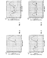
- Figure 2 illustrates the zero temperature coefficients loci for C mode of vibration (temperature coefficient A for C mode equal to zero), which are indicated at loci 8 and 10.
- the best known are the BT cut ((yxwl) 0 0 /-49.22 0 ), indicated in Figure 1 at 12, and the AT cut ((yxwl) 0°/35.25°), indicated in Figure 2 at 14.
- Holland considered all five factors simultaneously to compute the frequency transients of AT and BT resonators when thermally shocked, and also predicted a doubly rotated cut that was expected to be thermal-shock compensated as well as temperature compensated in the ordinary sense. Holland called it the TS cut ((yxwl) 22.8 0 /34.3 0 ).
- EerNisse reported an orientation for the slow thickness-shear mode of vibration, the SC cut ((yxwl) 22.5°/34.3°, which has approximately the same orientation as the TS cut and also lies on the previously known first order temperature locus.
- a thickness-shear resonator is useful in that it can be excited into resonance through the application of an external electric field, which is preferably applied to the resonator through electrodes formed thereon by means of vacuum deposition of conductive metals such as copper, or preferably gold.
- the resonant frequency (or frequencies if the resonator is excited in both thickness-shear modes of vibration) is dependent on the elastic coefficients, density, thickness, and overtone operation of the resonator.
- the resonant frequency shifts in relation to changes in temperature, pressure or externally applied force (for example, the stress caused by the electrodes at their boundaries with the resonator).
- quartz resonator The capability of a quartz resonator to experience a shift in its resonant frequency is quite useful in sensor applications (but not in frequency control) if the resonator is responding essentially to only one of the variables of temperature, pressure, voltage, or externally applied force within a relatively narrow operating range. If the resonator is responsive to more than one variable in its intended operating range, then it is necessary to be able to compensate for the variable(s) other than the one being measured in order to successfully measure the desired variable.
- the first approach utilizes a heated oven to control the frequency of the resonator.
- the resonator typically is cut in one of the temperature compensated orientations for which it has inherently good frequency stability over a narrow temperature range.
- Two widely used singly rotated orientations are the AT and BT, discussed above. While oscillators based on this approach.can have excellent frequency stability, several disadvantages have become apparent.
- the oven has become the predominant power user. Moreover, a thermal stabilization time of many minutes is required when the oven is first turned on.
- VCXO's Voltage Controlled Crystal Oscillators
- TCXO's Temporal Controlled Crystal Oscillators
- the VCXO typically includes a combination of a crystal resonator, an amplifier, and a voltage variable phase shifter.
- the voltage which is applied to the variable phase shifter represents a feedback signal derived from some form of temperature sensor, usually a. thermistor or thermistor bridge, although more elaborate methods are possible.
- the TCXO includes in the crystal resonator feedback path carefully selected reactive components which are not voltage variable, but which have a temperature- characteristic response which compensates for the temperature behavior of the crystal resonator.
- the third approach also utilizes characteristics of crystal resonators to obtain temperature compensation without the use of an oven.
- U.S. Patent No. 3,826,931 issued July 30, 1974 to Hammond, describes a resonator apparatus that utilizes either a single quartz crystal vibrating in two selected modes or two quartz crystals each vibrating in a signal selected mode to form a resonator output frequency that is the sum or difference of the two crystal frequencies.
- the temperature compensation described is static compensation, i.e., temperature compensation is achieved only under conditions where the ambient temperature is slowly changing. Rapidly changing temperatures sufficient to cause thermal gradients through the crystal resonator, cause instantaneous frequency shifts orders of magnitude greater than the static stability of the device.
- the AT cut resonator in an oven can have short term stabilities which are several parts in 10 10 .
- a 1° C . temperature gradient through the crystal resonator can cause a sudden frequency shift of 36 parts in 10 6 .
- the disadvantages of these approaches purportedly are overcome by the use of the SC cut, which appears to exhibit the necessary frequency-temperature stability over narrow temperature ranges to obtain good static compensation with either the first or second approach.
- the SC-cut is claimed to be frequency independent of internal stresses in the resonator caused by deposited electrode patterns, resonator mounts, and external applied stress in the major plane of the resonator.
- the SC cut is superior for certain applications to the AT and BT cuts in its frequency-temperature and frequency-stress behavior.
- orientations have been proposed which, for example, permit the measurement of temperature as a linear function of resonant frequency. See, for example, the Hammond-'609 patent. It has been necessary, however, to use a highly compliant (stress-attenuating) resonator mounting and enclosure.
- a quartz thermometer employing such means is commercially available from the Hewlett-Packard Company, Palo Alto, California, under model number 2804A (Electronic Instruments and Systems Catalog, 1981, p. 673).
- the LC cut resonator is ribbon-mounted in a stainless steel enclosure filled with a mixture of inert gases to minimize stress effects. See Hammond, D. & Benjaminson, A., The Linear Quartz Thermometer -- A New Tool for Measuring Absolute and Difference Temperature, Hewlett-Packard Journal, Vol. 16, No. 7, March 1965, pp. 1-7. Since these inert gases generally have a lower thermal conductivity than quartz, the response time of the Hewlett-Packard quartz thermometer accordingly is adversly affected.
- a resonator having a temperature compensated orientation with a significant nonzero value of the stress coefficient D may advantageously be used in a pressure sensor structure such as that disclosed, for example, in Figure 1 and pertinent textual portions of U.S. Patent No. 3,561,832, issued February 9, 1971 to Karrer et al., without need for elaborate temperature compensation techniques over a small temperature range.
- a pressure sensor structure such as that disclosed, for example, in Figure 1 and pertinent textual portions of U.S. Patent No. 3,561,832, issued February 9, 1971 to Karrer et al.
- the effect of any nonzero second and higher order temperature coefficients of this and the other orientations defined by either the B or C mode temperature compensated orientation loci introduces significant error into the pressure measurement. For this reason, high precision quartz pressure sensors with fast response time, large dynamic range, and precise operation over an extended temperation range are not available.
- An object of the invention therefore is to provide novel stress compensated orientations of quartz.
- a stress compensated thickness-shear resonator adapted to vibrate in at least one of its fast and slow thickness-shear modes of vibration at a frequency substantially determined by the thickness thereof, said resonator being of an orientation selected from the group comprising the orientations (yxwl) ⁇ / ⁇ defined by the loci of Figure 10 and the orientations (yxwl) ⁇ / ⁇ defined by the loci of Figure 11, plus or minus 4° in 0 end ⁇ .
- Another aspect of the invention includes a stress-compensated thickness-shear resonator adapted to vibrate in a slow thickness-shear mode at a frequency substantially determined by the thickness thereof, said resonator having a substantially circular major plane with a thickness axis normal thereto and having an orientation approximately (yxwl) 38.2°/-34.5°.
- an oscillator having stable frequency-stress behavior comprising: a stress compensated thickness-shear resonator adapted to vibrate in at least one of its fast and slow thickness-shear modes of vibration at a frequency substantially determined by the thickness thereof, said resonator being of an orientation selected from the group consisting of the orientations (yxwl) ⁇ / ⁇ defined by the loci of Figure 10 and the orientations (yxwl) ⁇ / ⁇ defined by the loci of Figure 11, plus or minus 4° in and 0 ; means for mounting said resonator and for transforming stresses arising from external pressure to uniform stresses in the major plane of said resonator; and excitation means for generating and supplying an electric field to said resonator for exciting said at least one thickness-shear mode.
- a further aspect of the invention includes an oscillator having stable frequency-stress behavior comprising: a stress compensated thickness-shear resonator adapted to vibrate in a slow thickness-shear mode of vibration at a frequency substantially determined by the thickness thereof, said resonator being of an orientation approximately (yxwl) 38.2°/-34.5°; means for mounting said resonator and for transforming stresses arising from external pressure to uniform stresses in the major plane of said resonator; and means for generating and supplying an electric field to said resonator for exciting said slow thickness-shear mode.
- a pressure sensor comprising: a stress-compensated thickness-shear resonator adapted to vibrate in fast thickness-shear and slow thickness-shear modes of vibration at respective frequencies substantially determined by the thickness thereof, said resonator being approximately of the orientation (yxwl) 16.3°/-34.5° and having opposite surfaces of selected contour spaced about a substantially circular major plane, and further being stress compensated for said fast thickness-shear mode and temperature compensated for said slow thickness mode; means for mounting said resonator and for transforming stresses arising from external pressure to uniform stresses in the major plane of said resonator; and means for generating and supplying an electric field to said resonator for exciting said fast and slow thickness-shear modes.
- quartz refers to crystalline material belonging to the trigonal crystal system, international point group 32, class D 3 (Schoenflies symbol).
- the orientation of a given quartz cut is specified in accordance with standards adopted by the Institute of Radio Engineers (now the Institute of Electrical and Electronic Engineers, or "IEEE”). See “Standards on Piezoelectric Crystals -- Standard 49 IRE 14.Sl," Proceedings of the I.R.E. 1949, Institute of Radio Engineers, December 1949, pp. 1378-90. Both singly rotated and doubly rotated cuts will be referred to herein by the nomenclature (yxwl) ⁇ / ⁇ , as is well known in the art.
- resonator refers to a cut of quartz material that is suitably shaped, contoured and polished such as to be capable of operation in the thickness-shear mode of vibration.
- Figure 3 illustrates a cross-section of a resonator 30, which preferably is a disk or a disk-like vibratory region of a rectangular plate suitably shaped and contoured and having diameter "d” and thickness "h,” for which X and Y are two of the three axes parallel and normal to the major plane of the resonator, respectively.
- Axes X and Y define orientation angles relative to the principal axes.
- both of the opposite surfaces of the resonator are contoured so as to produce a quartz crystal adapted for use as a bi-convex resonator.
- the contouring of the surfaces is desirable for the operation of the resonator in the trapped energy mode of vibration whereby the Q-factor of the resonator is increased.
- Electrodes 32 are provided for exciting the quartz material, and may comprise, for example, a thin metallic film vapor deposited on select areas of resonator 30.
- Electrodes 32 are provided for exciting the quartz material, and may comprise, for example, a thin metallic film vapor deposited on select areas of resonator 30.
- Figure 4 illustrates a top view of resonator 30.
- the third or Z axis of orientation of the vibratory plate is shown, as well as the arrows "F" representing opposite force vectors which when integrated 180° about the resonator result in radially uniform planar stresses acting on the resonator.
- the angle "a” is defined by the direction of discrete force vectors and the X-axis.
- a thickness mode quartz resonator vibrates in three modes of motion, the thickness-extensional or "A" mode, the fast thickness-shear or “B” mode, and the slow thickness-shear or “C” mode, such that resonant frequencies follow the relation f A >f B >f C .
- the displacement directions of the modes are mutually perpendicular in all materials, although the displacement directions relative to the resonator surface may differ as a function of the material. In isotropic or cubic material, two of the three displacement directions are shear and the third is thickness extension, and the directional displacements are either in the plane of the resonator or perpendicular to it.
- the natural resonant frequencies of a quartz resonator are affected by static mechanical stress bias, which can be caused by electrode stresses, externally applied load or mechanical mounts, and acceleration, in addition to uniform and nonuniform heating of the resonator.
- the mechanical stress bias is made to act on the resonator parallel to its major plane such that all stresses are radially uniform and planar within the resonator.
- the resonator is preferably a disk or a disk-like vibratory region.
- both the frequency-temperature and frequency-stress behavior of a quartz resonator can be represented by generalizing equation (1) as: where, as above, higher order terms can be ignored, and where "D" is the stress coefficient of frequency and / ⁇ P is the resonator stress minus a selected reference stress.
- the stress coefficient D must be made zero or practically zero. Quartz cuts having a stress coefficient of such value may be referred to as "stress compensated".
- the stress coefficient D of equation (2) is considered to be the mean stress coefficient ⁇ K f >, which is given by: where: and in which d and h are as defined above, F is the planar force in Newtons, N (which equals hf) is the frequency constant in meters/sec, and ⁇ f/f is the resulting fractional change in the resonant frequency for a given mode of vibration.
- a zero-valued mean force coefficients ⁇ K f > is found at (yxwl) 0.0°/21.0° (point 42).
- Zero-valued mean force coefficients ⁇ K f > are found at (yxwl) 10.0°/21° (point 44) and at (yxwl) 10.0°/-53° (point 46).
- Zero-valued mean force coefficients ⁇ K f > are found at (yxwl) 20.0°/22.2° (point 48) and at (yxwl) 20.0°/-50.4° (point 50).
- Zero-valued mean force coefficients ⁇ K f > are found at (yxwl) 30.0°/44.8° (point 52) and at (yxwl) 30.0°/-44.8° (point 54).
- a zero-valued mean force coefficients ⁇ K f > is found at (yxwl) 38.2°/-34.5° (point 56).
- the present invention includes respectively a singly rotated orientation 42 approximately equal to (yxwl) 0°/21.0° and a doubly rotated orientation 56 approximately equal to (yxwl) 38.2°/-34.5° (for C mode).
- the former cut has been christened the SRSC cut and the latter the SSC cut.
- the orientation of a particular resonator intended to be compensated against radially uniform in-plane stresses induced by such means as electrodes, externally applied load, mechanical mounts, or acceleration may vary by as much as +4° in ⁇ and/or e from a corresponding orientation indicated in Table 1 or Table 2, or in Figure 10 or 11.
- This variation is attributable to such factors as the type and degree of contouring applied to the quartz material, the quality of the quartz material, the shape, dimensions, and material of the electrodes (including, for example, the practice of partial electroding), the type of mounting in which the resonator is set, the operating temperature of the resonator, operation of the resonator in overtone modes of vibration, and reasonable investigatory and parametric uncertainties.
- a thickness-shear quartz resonator may be employed as a stabilizing element in an oscillator circuit.
- an oscillator may be considered to be a closed-loop system comprising an amplifier and a feedback network including the resonator.
- the amplitude builds to the point where nonlinearities decrease the loop gain to unity, while the frequency adjusts itself so that the total phase shift around the loop is zero (or 3600).
- the resonator possesses a large reactance frequency slope, and its impedance changes so sharply with frequency that other circuit components can be considered to be of constant reactance relative to the nominal frequency of the crystal.
- a quartz resonator in accordance with this invention will have an orientation for which the stress coefficient D is zero or a minimal value for at least one mode of vibration.
- An oscillator comprising such a resonator will be useful in frequency control applications, temperature measurement applications, and/or pressure measurement applications.
- the suitability of the resonator for a particular application depends on the respective values of its temperature coefficients A, B and C, the value of its stress coefficient D (if nonzero) relative to the value of the temperature coefficients, and the mode or modes of vibration which are exploited.
- the SSC cut and the other cuts having similar characteristics are particularly useful.
- the value of the temperature coefficient A in equation (4) is zero or a minimal value
- the temperature coefficients B and C have relatively small values
- the value of the stress coefficient D is zero or minimal.
- a resonator having one of these orientations is expected to have good long-term stability and fast thermal transient compensation.
- Suitable frequency-stable oscillator circuits are well known in the art.
- the resonator itself may have the configuration shown in Figure 12, in which the resonator is a disk-like vibratory region approximately between circular electrodes 72 deposited on respective surfaces of a quartz plate 70. Axes X and Z define the major plane.
- forces acting on plate 70 (for example, through a plate retaining structure, not shown) are resolved into radially uniform planar stress within the vibratory region. Since the plate has a stress compensated orientation, the resonator is relatively insensitive to the stress. Oscillation is maintained by oscillator 74.
- Other configurations are known. This. configuration basically is suitable for temperature measurement applications as well.
- the orientations defined by the coincidence of the B mode temperature compensated orientation loci ( Figure 1) and B mode stress compensated orientation loci ( Figure 10) and the coincidence of the C mode temperature compensated orientation loci ( Figure 2) and C mode stress compensated orientation loci ( Figure 11) will be particularly useful in frequency control applications.
- the orientations are (yxwl) ⁇ / ⁇ : 1°/-23.0°, 13.0°/-27.5° and 14.2°/-30.0°.
- the orientation is (yxwl) 38.2 0 /-34.5 0
- the SSC cut the SC cut is known). It should be noted, however, that the material Q for the B mode is usually higher than that for the C mode, which other factors being equal, means that the frequency stability of B mode resonators would be greater than the frequency stability of C mode resonators.
- the SRSC cut and cuts having similar characteristics are particularly useful.
- the value of the temperature coefficient A in equation (2) is relatively large, the temperature coefficients B and C have relatively small values, and the value of the stress coefficient D is zero or minimal. Consequently, a temperature sensor employing the SRSC cut is expected to measure relatively small differences in temperature with superior accuracy and sensitivity.
- a resonator having the SRSC orientation is expected to have good long-term stability, like a resonator having the known SC orientation.
- a resonator employing .
- the SRSC cut is capable of being brought in more immediate thermal contact with the environment being measured than the resonator of the Hewlett-Packard thermometer, since no high compliance enclosure need be used because of the stress compensated characteristic.
- a suitable mounting see Figure 12 and associated text would be provided, such mountings being known in the art.
- the orientations defined by the B mode stress compensated orientation loci ( Figure 10) and the C mode stress compensated orientation loci ( Figure 11), and having large-valued temperature coefficients A, B and/or C will be useful in temperature measurement control applications. Values for the temperature coefficients A, B and C are known in the art.
- the SRSC cut is particularly useful, however, because it is a singly rotated cut (and therefore more easily fabricated than a doubly rotated cut) and has a large-valued A and relatively small-valued B and C.
- orientations defined by the coincidence of the B mode stress compensated orientation loci ( Figure 10) and the C mode stress compensated orientation loci ( Figure 11) will be particularly useful in precision temperature measurement control applications. Respective independent temperature measurements are available from B and C modes of vibration of the same resonator, thereby providing redundant indications for the parameter being measured and also permitting detection of erroneous device operation if independent oscillator circuitry is used.
- the orientations are (yxwl) ⁇ / ⁇ : 7.0°/20.0°, 24.7°/27.8° and 22.8°/-49.5°.
- an orientation of particular suitability is (yxwl) 16.3°/-34.5°, defined by the coincidence of the B mode stress compensated orientation loci ( Figure 10) with the C mode temperature compensated orientation loci ( Figure 2).
- a quartz cut having this orientation is hereinafter referred to as the SBTC (Stress Compensated in B mode and Temperature Compensated in C mode) cut.
- a resonator of this orientation may be excited to vibrate in both B and C modes.
- Pressure measurements may be obtained from C mode. Over a broad range of temperatures and pressures, however, B mode frequencies would include small errors due to temperature effects while C mode frequencies would include small errors due to stress effects.
- the C mode frequencies may be corrected for the extremely small but troublesome temperature effects using temperature measurements obtained from B mode, as explained below.
- the quantities ⁇ T and ⁇ P are determined by inverting the coefficient matrix in Equation (7). For greatest resolution the diagonal elements should be dominant, which requires, for example, that MB>>DB and D C >>M C .
- the first step is a calibration process in which both the B and C mode frequencies are measured at selected temperatures and pressures over the required operating range.
- the actual frequencies of the B and C modes can be expressed as respective polynomials in temperature and pressure: where f B is the actual B mode frequency, f BR is the B mode reference frequency, f c and f CR are similarly defined for C mode, and the other terms are as defined above.
- the actual B mode frequency f B can be measured using the C mode frequency f C as the reference.
- the frequencies f B can be determined as a function of temperature and fixed pressure from the relation: where f BM and f CM are the measured frequencies for B and C modes, respectively.
- f B (T,P) Several values of f B (T,P) are thus obtained for various temperature and pressure data, whereby, the temperature of the probe can be expressed as polynomial of the form: at a fixed pressure.
- This curve fitting routine can be implemented on any suitable processor or general purpose computer, whereby the temperature induced error in the C-mode frequency can be compensated to provide the shift in the reference frequency f CR as a function of applied pressure and independent of temperature fluctuations.
- the SBTC cut may advantageously be used in a pressure sensor structure such as that disclosed, for example, in Figure 1 and pertinent textual portions of U.S. Patent No. 3,561,832 (issued February 9, 1971 to Karrer et al.), hereby incorporated herein by reference thereto, and combined with suitable circuitry for extremely precise pressure measurement.
- a high-precision pressure sensor system particularly suitable for use in oil well logging of earth formations through which a borehole passes is shown in Figure 13.
- a suitable quartz pressure sensor generally indicated at 100 comprises a quartz resonator 102 having the SBTC orientation (yxwl) 16.3°/-34.5° (+ 4° in ⁇ and/or 9) or an orientation sufficiently close thereto to exhibit the characteristics described in reference to Equation (7) disposed between electrodes 104.
- the pressure sensor 100 and associated downhole electronics 106 typically are mounted in a logging device such as, for example, the tool to take multiple formation fluid pressures disclosed in U.S. Patent No. 3,577,781, issued May 4, 1971 to Levier et al. hereby incorporated herein by reference thereto.
- the resonator 102 is made to vibrate simultaneously in both the B and C modes of vibration by application of an AC signal to electrodes 104 by amplifiers 107 and 108 corresponding to the B and C mode frequencies, respectively.
- Filter networks 109 and 110 each having appropriate poles and/or zeros relative to the B and C mode frequencies respectively, are provided to separate the energy from the variation in the two modes of the single pair of electrodes 104.
- the B and C mode signals from amplifiers 107 and 108 are applied to respective digitizers 117 and 118.
- the digitized signals are applied to telemetry system 120 where they are multiplexed and transmitted to the surface equipment, generally indicated at 130, over an armored cable 125.
- the logging device is suspended in the borehole on the armored cable 125, the length of which substantially determines the relative depth of the logging device.
- the length of armored cable 125 is controlled by suitable means at the surface, such as a drum and winch mechanism 129.
- the armored cable 125 is rewound on the drum to raise the logging device toward the surface as measurements are taken.
- Depth measurements are provided by a measure wheel 127 or other suitable means.
- Telemetry signals transmitted over armored cable 125 are supplied to telemetry system 132 through the drum and winch mechanism 129.
- the signals are demultiplexed and the digital frequency information for the B and C modes is supplied to processor 134.
- Processor 134 determines the temperature compensated pressure in accordance with the curve fitting routine described above or any other suitable method, and supplies this information to recorder 136 which, receiving depth information from measure wheel 127, records pressure as a function of depth.
Landscapes
- Physics & Mathematics (AREA)
- Acoustics & Sound (AREA)
- Piezo-Electric Or Mechanical Vibrators, Or Delay Or Filter Circuits (AREA)
Applications Claiming Priority (4)
| Application Number | Priority Date | Filing Date | Title |
|---|---|---|---|
| US20440080A | 1980-11-05 | 1980-11-05 | |
| US204400 | 1980-11-05 | ||
| US06/267,507 US4419600A (en) | 1980-11-05 | 1981-05-27 | Stress-compensated quartz resonators |
| US267507 | 1981-05-27 |
Publications (2)
| Publication Number | Publication Date |
|---|---|
| EP0054447A1 true EP0054447A1 (fr) | 1982-06-23 |
| EP0054447B1 EP0054447B1 (fr) | 1988-09-14 |
Family
ID=26899442
Family Applications (1)
| Application Number | Title | Priority Date | Filing Date |
|---|---|---|---|
| EP81401760A Expired EP0054447B1 (fr) | 1980-11-05 | 1981-11-03 | Résonateurs à quartz compensés en tension |
Country Status (4)
| Country | Link |
|---|---|
| US (1) | US4419600A (fr) |
| EP (1) | EP0054447B1 (fr) |
| CA (1) | CA1175546A (fr) |
| DE (1) | DE3176879D1 (fr) |
Cited By (3)
| Publication number | Priority date | Publication date | Assignee | Title |
|---|---|---|---|---|
| GB2176892A (en) * | 1985-06-17 | 1987-01-07 | Yokogawa Hokushin Electric | Quartz resonator thermometer |
| EP0206944A3 (en) * | 1985-06-26 | 1989-03-22 | Schlumberger Limited | Stress and temperature compensated surface acoustic wave devices |
| WO2009004429A1 (fr) * | 2007-07-02 | 2009-01-08 | Schlumberger Technology B.V. | Capteur de pression |
Families Citing this family (17)
| Publication number | Priority date | Publication date | Assignee | Title |
|---|---|---|---|---|
| FR2531532A1 (fr) * | 1982-08-05 | 1984-02-10 | Flopetrol | Capteur piezo-electrique, notamment pour la mesure de pressions |
| US5577308A (en) * | 1995-02-28 | 1996-11-26 | Motorola, Inc. | Method of rotating a Bechmann curve of a quartz strip resonator |
| US6085594A (en) * | 1998-09-04 | 2000-07-11 | The United States Of America As Represented By The Administrator Of The National Aeronautics And Space Administration | High resolution and large dynamic range resonant pressure sensor based on Q-factor measurement |
| US6111340A (en) * | 1999-04-12 | 2000-08-29 | Schlumberger Technology Corporation | Dual-mode thickness-shear quartz pressure sensors for high pressure and high temperature applications |
| US6147437A (en) * | 1999-08-11 | 2000-11-14 | Schlumberger Technology Corporation | Pressure and temperature transducer |
| US6744182B2 (en) | 2001-05-25 | 2004-06-01 | Mark Branham | Piezoelectric quartz plate and method of cutting same |
| JP2004007420A (ja) * | 2002-03-26 | 2004-01-08 | Seiko Epson Corp | 圧電振動片、圧電振動子および圧電デバイス |
| JP4368219B2 (ja) * | 2004-02-20 | 2009-11-18 | 日本電波工業株式会社 | 水晶発振器、発振方法及びヒータ |
| US8136406B2 (en) | 2009-03-31 | 2012-03-20 | Schlumberger Technology Corporation | Pressure transducer with piezoelectric crystal for harsh environment use |
| US8429976B2 (en) | 2010-05-19 | 2013-04-30 | Schlumberger Technology Corporation | Low cost resonator-based pressure transducer |
| US8569937B1 (en) | 2010-07-13 | 2013-10-29 | Hrl Laboratories, Llc | Piezoelectric resonator with capacitive sense and/or force rebalance electrodes to control an amplitude of vibration |
| US8305154B1 (en) * | 2010-07-13 | 2012-11-06 | Hrl Laboratories, Llc | Parametrically driven quartz UHF oscillator |
| US9038263B2 (en) | 2011-01-13 | 2015-05-26 | Delaware Capital Formation, Inc. | Thickness shear mode resonator sensors and methods of forming a plurality of resonator sensors |
| US8933759B1 (en) | 2012-07-13 | 2015-01-13 | Hrl Laboratories, Llc | Dynamic damping in a quartz oscillator |
| WO2015006536A1 (fr) | 2013-07-11 | 2015-01-15 | Schlumberger Canada Limited | Applications de résonateur pour langasite et ses isomorphes |
| US10451508B2 (en) | 2016-06-03 | 2019-10-22 | Schlumberger Technology Corporation | Pressure transducer and method for fabricating the same |
| CN111404507B (zh) * | 2020-03-30 | 2024-04-02 | 西安电子科技大学 | 一种采用条形补偿膜应力补偿的晶体谐振器 |
Citations (3)
| Publication number | Priority date | Publication date | Assignee | Title |
|---|---|---|---|---|
| US3202846A (en) * | 1963-04-03 | 1965-08-24 | Arthur D Ballato | Piezoelectric crystal element |
| DE2407852A1 (de) * | 1973-02-20 | 1974-09-05 | Fujitsu Ltd | Quarzkristalleinheit |
| US3979614A (en) * | 1973-10-24 | 1976-09-07 | Kinsekisha Laboratory, Ltd. | DT cut, contour mode piezoelectric crystal |
Family Cites Families (8)
| Publication number | Priority date | Publication date | Assignee | Title |
|---|---|---|---|---|
| BE424774A (fr) * | 1936-11-25 | |||
| US2743144A (en) * | 1951-04-07 | 1956-04-24 | Motorola Inc | Zero temperature coefficient piezoelectric crystal |
| US3423609A (en) * | 1964-01-30 | 1969-01-21 | Hewlett Packard Co | Quartz crystal temperature transducer |
| US3826931A (en) * | 1967-10-26 | 1974-07-30 | Hewlett Packard Co | Dual crystal resonator apparatus |
| US3577781A (en) * | 1969-01-10 | 1971-05-04 | Schlumberger Technology Corp | Tool to take multiple formation fluid pressures |
| US3561832A (en) * | 1969-12-05 | 1971-02-09 | Hewlett Packard Co | Quartz resonator pressure transducer |
| US4079280A (en) * | 1976-06-02 | 1978-03-14 | Hewlett-Packard Company | Quartz resonator cut to compensate for static and dynamic thermal transients |
| US4160183A (en) * | 1978-05-26 | 1979-07-03 | Hewlett-Packard Company | Oscillator having a quartz resonator cut to compensate for static and dynamic thermal transients |
-
1981
- 1981-05-27 US US06/267,507 patent/US4419600A/en not_active Expired - Fee Related
- 1981-11-03 EP EP81401760A patent/EP0054447B1/fr not_active Expired
- 1981-11-03 DE DE8181401760T patent/DE3176879D1/de not_active Expired
- 1981-11-05 CA CA000389468A patent/CA1175546A/fr not_active Expired
Patent Citations (3)
| Publication number | Priority date | Publication date | Assignee | Title |
|---|---|---|---|---|
| US3202846A (en) * | 1963-04-03 | 1965-08-24 | Arthur D Ballato | Piezoelectric crystal element |
| DE2407852A1 (de) * | 1973-02-20 | 1974-09-05 | Fujitsu Ltd | Quarzkristalleinheit |
| US3979614A (en) * | 1973-10-24 | 1976-09-07 | Kinsekisha Laboratory, Ltd. | DT cut, contour mode piezoelectric crystal |
Non-Patent Citations (1)
| Title |
|---|
| IEEE Transactions on Sonics and Ultrasonics, Vol. SU-23, No. 4, July 1976 New York (US) J.A. KUSTERS: "Transient Thermal Compensation for Quartz Resonators" pages 273-276 *the whole document* * |
Cited By (7)
| Publication number | Priority date | Publication date | Assignee | Title |
|---|---|---|---|---|
| GB2176892A (en) * | 1985-06-17 | 1987-01-07 | Yokogawa Hokushin Electric | Quartz resonator thermometer |
| GB2176892B (en) * | 1985-06-17 | 1989-05-10 | Yokogawa Hokushin Electric | Quartz thermometer |
| EP0206944A3 (en) * | 1985-06-26 | 1989-03-22 | Schlumberger Limited | Stress and temperature compensated surface acoustic wave devices |
| WO2009004429A1 (fr) * | 2007-07-02 | 2009-01-08 | Schlumberger Technology B.V. | Capteur de pression |
| GB2465091A (en) * | 2007-07-02 | 2010-05-12 | Schlumberger Holdings | Pressure transducer |
| GB2465091B (en) * | 2007-07-02 | 2011-11-09 | Schlumberger Holdings | Pressure transducer |
| US8294332B2 (en) | 2007-07-02 | 2012-10-23 | Schlumberger Technology Corporation | Pressure transducer |
Also Published As
| Publication number | Publication date |
|---|---|
| EP0054447B1 (fr) | 1988-09-14 |
| US4419600A (en) | 1983-12-06 |
| DE3176879D1 (en) | 1988-10-20 |
| CA1175546A (fr) | 1984-10-02 |
Similar Documents
| Publication | Publication Date | Title |
|---|---|---|
| EP0054447B1 (fr) | Résonateurs à quartz compensés en tension | |
| US4079280A (en) | Quartz resonator cut to compensate for static and dynamic thermal transients | |
| Eernisse et al. | Survey of quartz bulk resonator sensor technologies | |
| US4160183A (en) | Oscillator having a quartz resonator cut to compensate for static and dynamic thermal transients | |
| US3561832A (en) | Quartz resonator pressure transducer | |
| EP0161533B1 (fr) | Transducteur de température à résonance | |
| US10355664B2 (en) | Resonator applications for langasite and its isomorphs | |
| US4039969A (en) | Quartz thermometer | |
| Malocha et al. | Recent measurements of material constants versus temperature for langatate, langanite and langasite | |
| US4398115A (en) | Temperature probe using a plate of quartz | |
| US4472656A (en) | Temperature sensor and method using a single rotated quartz crystal | |
| JPS60105917A (ja) | 共振変換システム、共振力変換システム及び力又は他のパラメ−タ−と温度の決定方法 | |
| Vig | Temperature-insensitive dual-mode resonant sensors-a review | |
| GB2188421A (en) | Vibrating beam force transducer with a-frame beam root and frequency adjusting means | |
| Yong et al. | On the accuracy of Mindlin plate predictions for the frequency-temperature behavior of resonant modes in AT-and SC-cut quartz plates | |
| Gerber et al. | State of the art—Quartz crystal units and oscillators | |
| Pan et al. | The influence of pressure on the TCF of AlN-based SAW pressure sensor | |
| Sinha et al. | Recent developments in high precision quartz and Langasite pressure sensors for high temperature and high pressure applications | |
| EerNisse | Quartz resonators vs their environment: Time base or sensor? | |
| CA1139583A (fr) | Methode de compensation des variations de temperature dans les dispositifs a ondes de surface et transducteur de pression utilisant cette methode | |
| O’Hara | Influence of pressure, temperature, and pore fluid on the frequency-dependent attenuation of elastic waves in Berea sandstone | |
| JPS6222041A (ja) | レゾネ−タ圧力トランスデユ−サ | |
| Gerber et al. | Quartz frequency standards | |
| US4486682A (en) | Stress compensated quartz resonator having ultra-linear frequency-temperature response | |
| Flynn et al. | An improved cryogenic thermometer |
Legal Events
| Date | Code | Title | Description |
|---|---|---|---|
| PUAI | Public reference made under article 153(3) epc to a published international application that has entered the european phase |
Free format text: ORIGINAL CODE: 0009012 |
|
| AK | Designated contracting states |
Designated state(s): DE FR GB IT NL |
|
| 17P | Request for examination filed |
Effective date: 19821209 |
|
| GRAA | (expected) grant |
Free format text: ORIGINAL CODE: 0009210 |
|
| AK | Designated contracting states |
Kind code of ref document: B1 Designated state(s): DE FR GB IT NL |
|
| ITF | It: translation for a ep patent filed | ||
| REF | Corresponds to: |
Ref document number: 3176879 Country of ref document: DE Date of ref document: 19881020 |
|
| ET | Fr: translation filed | ||
| PLBE | No opposition filed within time limit |
Free format text: ORIGINAL CODE: 0009261 |
|
| STAA | Information on the status of an ep patent application or granted ep patent |
Free format text: STATUS: NO OPPOSITION FILED WITHIN TIME LIMIT |
|
| 26N | No opposition filed | ||
| ITTA | It: last paid annual fee | ||
| PGFP | Annual fee paid to national office [announced via postgrant information from national office to epo] |
Ref country code: NL Payment date: 19911130 Year of fee payment: 11 |
|
| PGFP | Annual fee paid to national office [announced via postgrant information from national office to epo] |
Ref country code: DE Payment date: 19911227 Year of fee payment: 11 |
|
| PG25 | Lapsed in a contracting state [announced via postgrant information from national office to epo] |
Ref country code: NL Effective date: 19930601 |
|
| NLV4 | Nl: lapsed or anulled due to non-payment of the annual fee | ||
| PG25 | Lapsed in a contracting state [announced via postgrant information from national office to epo] |
Ref country code: DE Effective date: 19930803 |
|
| PGFP | Annual fee paid to national office [announced via postgrant information from national office to epo] |
Ref country code: GB Payment date: 19930929 Year of fee payment: 13 |
|
| PGFP | Annual fee paid to national office [announced via postgrant information from national office to epo] |
Ref country code: FR Payment date: 19931028 Year of fee payment: 13 |
|
| PG25 | Lapsed in a contracting state [announced via postgrant information from national office to epo] |
Ref country code: GB Effective date: 19941103 |
|
| GBPC | Gb: european patent ceased through non-payment of renewal fee |
Effective date: 19941103 |
|
| PG25 | Lapsed in a contracting state [announced via postgrant information from national office to epo] |
Ref country code: FR Effective date: 19950731 |
|
| REG | Reference to a national code |
Ref country code: FR Ref legal event code: ST |