EP0054457B1 - Vergaser mit zentraler Gemischzugabe - Google Patents
Vergaser mit zentraler Gemischzugabe Download PDFInfo
- Publication number
- EP0054457B1 EP0054457B1 EP81401875A EP81401875A EP0054457B1 EP 0054457 B1 EP0054457 B1 EP 0054457B1 EP 81401875 A EP81401875 A EP 81401875A EP 81401875 A EP81401875 A EP 81401875A EP 0054457 B1 EP0054457 B1 EP 0054457B1
- Authority
- EP
- European Patent Office
- Prior art keywords
- carburetor
- air
- circuit
- mixture supply
- air mixture
- Prior art date
- Legal status (The legal status is an assumption and is not a legal conclusion. Google has not performed a legal analysis and makes no representation as to the accuracy of the status listed.)
- Expired
Links
- 239000000446 fuel Substances 0.000 title claims description 5
- 239000000203 mixture Substances 0.000 title claims description 4
- 239000000839 emulsion Substances 0.000 claims description 8
- 238000011144 upstream manufacturing Methods 0.000 claims description 4
- 238000002485 combustion reaction Methods 0.000 claims description 3
- 230000003247 decreasing effect Effects 0.000 description 1
- 239000002828 fuel tank Substances 0.000 description 1
- 229910001234 light alloy Inorganic materials 0.000 description 1
- 230000001052 transient effect Effects 0.000 description 1
Images
Classifications
-
- F—MECHANICAL ENGINEERING; LIGHTING; HEATING; WEAPONS; BLASTING
- F02—COMBUSTION ENGINES; HOT-GAS OR COMBUSTION-PRODUCT ENGINE PLANTS
- F02M—SUPPLYING COMBUSTION ENGINES IN GENERAL WITH COMBUSTIBLE MIXTURES OR CONSTITUENTS THEREOF
- F02M19/00—Details, component parts, or accessories of carburettors, not provided for in, or of interest apart from, the apparatus of groups F02M1/00 - F02M17/00
- F02M19/08—Venturis
-
- Y—GENERAL TAGGING OF NEW TECHNOLOGICAL DEVELOPMENTS; GENERAL TAGGING OF CROSS-SECTIONAL TECHNOLOGIES SPANNING OVER SEVERAL SECTIONS OF THE IPC; TECHNICAL SUBJECTS COVERED BY FORMER USPC CROSS-REFERENCE ART COLLECTIONS [XRACs] AND DIGESTS
- Y10—TECHNICAL SUBJECTS COVERED BY FORMER USPC
- Y10S—TECHNICAL SUBJECTS COVERED BY FORMER USPC CROSS-REFERENCE ART COLLECTIONS [XRACs] AND DIGESTS
- Y10S261/00—Gas and liquid contact apparatus
- Y10S261/39—Liquid feeding nozzles
Definitions
- Carburetors comprising a combustion air passage duct provided with a Venturi-shaped part at the neck of which an inlet passage of an air-petrol emulsion opens.
- a mixing centralizer is provided which divides the combustion air passage into an internal circuit and an external circuit, an air-fuel emulsion inlet pipe opening laterally into the circuit. inside, and which is placed so that its downstream edge is at the neck of the air passage.
- the quantity of petrol admitted into the air passage duct depends on the vacuum which is generated by the internal circuit at the level of the inlet duct of the air-petrol emulsion.
- the centering devices are most often at present constituted by a simple cylindrical tube in which the emulsion inlet duct opens out laterally.
- centralizers whose internal circuit has the shape of a Venturi, the emulsion inlet conduits opening approximately at the Venturi neck (DE-C-833 882, US-A-2 495 299).
- the flow of air in the internal circuit generates a greater depression at the Venturi neck of the centering device, which allows more gas to be drawn in.
- This type of centering device is more stable than the previous one.
- the present invention relates to a carburetor with a mixing centralizer whose operation is improved compared to the known device.
- This carburetor is characterized in that the interior air circuit essentially comprises a cylindrical part with parallel faces (8a) on the upstream side and a frustoconical part with parallel faces (8b) on the downstream side, the inclination of the internal and external faces of the frustoconical part (8b) being the same as that of the diffuser (3a) of the carburetor.
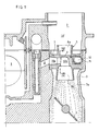
- a carburetor comprising in the usual manner a fuel tank 1 and an air passage duct 2 which has a neck 3 followed by a diffuser 3a and an adjusting butterfly 4 disposed downstream of the neck .
- a centering device 5 is placed in the passage 2, upstream from the neck 3, and allows this air-fuel emulsion to be admitted to this neck which arrives via a conduit 6.
- the centralizer 5 comprises a body 7, preferably of light alloy, which is traversed by a thin-walled conduit, with parallel faces, of vertical axis and of circular section.
- the upper part 8a of this duct is cylindrical externally and internally.
- Its lower part 8b is tapered internally and externally; its taper is the same as that of the diffuser 3a of the carburetor.
- the two parts 8a and 8b are substantially the same height.
- the body 7 In its middle part, the body 7 is crossed by a horizontal element 9.
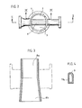
- This element 9 projects laterally on either side of the body 7 and its outer section has the shape of a rectangle whose upper edge is rounded (see figure 4). It is pierced with a right angle conduit which comprises an inlet portion 1 Oa opening facing the passage 6, and an outlet portion 10b which opens approximately at the center of the vertical conduit 8a-8b and is directed downwards.
- the inlet portion 1 Oa has a rectangular cross section with rounded upper edge, like the element 9. This section is decreasing from the inlet of the conduit to its connection with the outlet portion 1 Ob.
- This outlet portion is frustoconical and thus forms a diffuser; its taper is the same as that of the internal face of the lower part 8b of the centralizer duct.
- the horizontal element 9 also comprises, on the side opposite to the inlet portion 10a, a blind recess (11) in which is housed a spring 12 placing the centering device in abutment on the wall of the carburetor into which the passage 6 opens.
- This centering device is arranged in the air passage circuit of the carburetor 2 so that the base of the body 7 is at the level of the neck 3 of this duct.
- the centralizer divides the air flow passing through the conduit 2 into an external circuit which passes around the centralizer and into an internal circuit which passes through the conduit 8a-8b.
- the internal circuit generates a vacuum in the conduit 10b so that air-fuel emulsion is drawn into the passage 6 and enters the conduit 2.
- the centering device which has just been described promotes the flow of the air circuit inside the centering device over the flow rate of the outside air circuit.
- the air which passes inside the centering device and which contains the aspirated petrol manages to bypass the butterfly, on two opposite sides of it and mixes with the air of the external circuit, as shown in Figure 1.
- the air charged with petrol is maintained by the air in the external circuit. laughing in the central part of the duct 2. It crosses the butterfly asymmetrically, predominantly on the side of the lower downstream edge of this butterfly.
- the flow rate of the interior air circuit is favored by the centralizer according to the invention, it corresponds to a lower depression at the neck 3 so that the resulting mixture downstream of the butterfly valve 4 is both poorer and more homogeneous.
- the main jet of the carburetor being adjusted for optimal operation at normal speed, the mixture is optimized for a greater speed range than with the usual centralizers; furthermore, transient operation does not present any instabilities.
Landscapes
- Engineering & Computer Science (AREA)
- Chemical & Material Sciences (AREA)
- Combustion & Propulsion (AREA)
- Mechanical Engineering (AREA)
- General Engineering & Computer Science (AREA)
- Control Of The Air-Fuel Ratio Of Carburetors (AREA)
- Spray-Type Burners (AREA)
Claims (1)
- Vergaser mit zentraler, den Verbrennungsluft-Durchlass (2) in einen inneren und einen äusseren Durchgang aufteilenden Gemischzugabe (5) und einer seitlich in den inneren Durchgang einmündenden Luft-Kraftstoff-Gemisch-Zuführung (6), dadurch gekennzeichnet, dass der innere Verbrennungsluft-Durchgang im wesentlichen auf der Einlassseite einen zylindrischen Teil (8a) mit planparallelen Wandungen und auf der Auslassseite einen kegelstumpfartigen Teil (8b) mit ebenfalls planparallelen Wandungen aufweist, wobei die Neigung der inneren und äusseren Wandungen des kegelstumpfartigen Teils (8b) derjenigen des Diffusors (3a) des Vergasers entspricht.
Applications Claiming Priority (2)
| Application Number | Priority Date | Filing Date | Title |
|---|---|---|---|
| FR8026853A FR2496177B1 (fr) | 1980-12-15 | 1980-12-15 | Carburateur a centreur de melange |
| FR8026853 | 1980-12-15 |
Publications (2)
| Publication Number | Publication Date |
|---|---|
| EP0054457A1 EP0054457A1 (de) | 1982-06-23 |
| EP0054457B1 true EP0054457B1 (de) | 1985-01-16 |
Family
ID=9249212
Family Applications (1)
| Application Number | Title | Priority Date | Filing Date |
|---|---|---|---|
| EP81401875A Expired EP0054457B1 (de) | 1980-12-15 | 1981-11-26 | Vergaser mit zentraler Gemischzugabe |
Country Status (6)
| Country | Link |
|---|---|
| US (1) | US4464313A (de) |
| EP (1) | EP0054457B1 (de) |
| JP (1) | JPS57165653A (de) |
| DE (1) | DE3168401D1 (de) |
| ES (1) | ES269987Y (de) |
| FR (1) | FR2496177B1 (de) |
Families Citing this family (5)
| Publication number | Priority date | Publication date | Assignee | Title |
|---|---|---|---|---|
| JPS59160841U (ja) * | 1983-04-15 | 1984-10-27 | トヨタ自動車株式会社 | 気化器 |
| US5273688A (en) * | 1991-12-09 | 1993-12-28 | Gilbert J. Eastin | Carburetor air volume control |
| JP2000297703A (ja) * | 1999-04-09 | 2000-10-24 | Nippon Walbro:Kk | 気化器の燃料ジエツト支持構造 |
| RU2173786C2 (ru) * | 1999-09-20 | 2001-09-20 | Общество с ограниченной ответственностью "Топливные системы" | Карбюратор для двигателя внутреннего сгорания |
| RU2191281C2 (ru) * | 1999-11-09 | 2002-10-20 | Государственный научно-производственный ракетно-космический центр "ЦСКБ-Прогресс" | Смесительное устройство для системы питания карбюраторного двигателя |
Family Cites Families (14)
| Publication number | Priority date | Publication date | Assignee | Title |
|---|---|---|---|---|
| US1418756A (en) * | 1922-06-06 | Sidney d | ||
| DE595128C (de) * | 1930-10-05 | 1934-04-06 | Vesta Buchpruefungs Und Treuha | Schwimmerloser Vergaser |
| US2152057A (en) * | 1938-02-05 | 1939-03-28 | Frank A Kane | Nozzle |
| US2328764A (en) * | 1940-07-26 | 1943-09-07 | Bendix Aviat Corp | Carburetor |
| IT454350A (de) * | 1946-10-12 | |||
| US2495299A (en) * | 1947-09-30 | 1950-01-24 | Bendix Aviat Corp | Charge forming device |
| DE833882C (de) * | 1950-09-02 | 1952-03-13 | Hans Westermeier | Vergaser fuer Brennkraftmaschinen |
| US2996290A (en) * | 1959-03-23 | 1961-08-15 | Munden Vernon | Gasoline saver for internal combustion engines |
| US3648988A (en) * | 1970-07-06 | 1972-03-14 | Oliver D Dibert | Carbureting device |
| DE2330709A1 (de) * | 1973-06-16 | 1975-01-09 | Audi Nsu Auto Union Ag | Einrichtung zur kraftstoff-luftgemiwch-bildung bei brennkraftmaschinen |
| JPS524925A (en) * | 1975-07-02 | 1977-01-14 | Hitachi Ltd | Jet carburetor |
| US4146596A (en) * | 1975-07-31 | 1979-03-27 | Nissan Motor Company, Limited | Intake system of an internal combustion engine |
| JPS5314236A (en) * | 1976-07-23 | 1978-02-08 | Hitachi Ltd | Carbureter |
| JPS53140820U (de) * | 1977-04-14 | 1978-11-07 |
-
1980
- 1980-12-15 FR FR8026853A patent/FR2496177B1/fr not_active Expired
-
1981
- 1981-11-20 ES ES1981269987U patent/ES269987Y/es not_active Expired
- 1981-11-26 EP EP81401875A patent/EP0054457B1/de not_active Expired
- 1981-11-26 DE DE8181401875T patent/DE3168401D1/de not_active Expired
- 1981-12-10 JP JP56199452A patent/JPS57165653A/ja active Pending
-
1983
- 1983-11-21 US US06/553,876 patent/US4464313A/en not_active Expired - Fee Related
Also Published As
| Publication number | Publication date |
|---|---|
| DE3168401D1 (en) | 1985-02-28 |
| ES269987U (es) | 1983-07-01 |
| FR2496177A1 (fr) | 1982-06-18 |
| EP0054457A1 (de) | 1982-06-23 |
| ES269987Y (es) | 1984-01-16 |
| FR2496177B1 (fr) | 1985-10-11 |
| JPS57165653A (en) | 1982-10-12 |
| US4464313A (en) | 1984-08-07 |
Similar Documents
| Publication | Publication Date | Title |
|---|---|---|
| EP0928252A1 (de) | Kraftstoffzuführeinrichtung für einen kraftfahrzeugtank | |
| EP0054457A1 (de) | Vergaser mit zentraler Gemischzugabe | |
| FR2538036A1 (fr) | Suppresseur de gaz d'echappement pour moteurs a combustion interne | |
| US20060092758A1 (en) | Fluid mixing venturi | |
| FR2559547A1 (fr) | Soupape a monter dans un coude d'une conduite de fluide de moteur a combustion interne | |
| FR2519079A1 (fr) | Pulverisateur de carburant pour chambre de combustion de turbomachines | |
| FR2517748A1 (fr) | Tubulure de raccordement du carburateur d'un moteur a combustion interne | |
| FR2686946A1 (fr) | Carburateur pour un moteur thermique. | |
| FR2573485A1 (fr) | Dispositif de formation du melange pour des moteurs a combustion interne a plusieurs cylindres | |
| FR2490732A1 (fr) | Carburateur a filtre a air pour moteur a combustion interne | |
| CA3141613A1 (fr) | Canne de prevaporisation, ensemble de combustion muni de celle-ci et turbomachine munie de celui-ci | |
| FR2652388A1 (fr) | Carburateur avec un systeme de ralenti independant. | |
| FR2524072A1 (fr) | Carburateur a venturi variable | |
| FR2542378A1 (fr) | Dispositif d'alimentation en gaz pour moteur a combustion interne | |
| FR2491150A1 (fr) | Dispositif d'admission pour moteur a combustion interne | |
| EP0361600B1 (de) | Zerstäubungsdüse für Vergaser einer gemischverdichtenden Brennkraftmaschine | |
| FR2482201A1 (fr) | Perfectionnements aux carburateurs comportant un circuit principal et un circuit auxiliaire | |
| CH127358A (fr) | Carburateur pour moteur à combustion interne. | |
| FR2515737A1 (fr) | Carburateur pour moteur a combustion interne | |
| FR2459887A1 (fr) | Perfectionnements aux carburateurs inverses pour moteurs a combustion interne | |
| FR2698662A1 (fr) | Dispositif assurant la combustion complète du mélange d'air et de carburant liquide alimentant les moteurs à combustion interne. | |
| FR2525690A1 (fr) | Carburateur pour moteur a combustion interne a circuit de ralenti | |
| BE346439A (de) | ||
| CH259924A (fr) | Carburateur pour moteur à combustion interne. | |
| CH212011A (fr) | Carburateur pour moteur à combustion interne. |
Legal Events
| Date | Code | Title | Description |
|---|---|---|---|
| PUAI | Public reference made under article 153(3) epc to a published international application that has entered the european phase |
Free format text: ORIGINAL CODE: 0009012 |
|
| AK | Designated contracting states |
Designated state(s): DE GB IT SE |
|
| 17P | Request for examination filed |
Effective date: 19820713 |
|
| ITF | It: translation for a ep patent filed | ||
| GRAA | (expected) grant |
Free format text: ORIGINAL CODE: 0009210 |
|
| AK | Designated contracting states |
Designated state(s): DE GB IT SE |
|
| REF | Corresponds to: |
Ref document number: 3168401 Country of ref document: DE Date of ref document: 19850228 |
|
| REG | Reference to a national code |
Ref country code: GB Ref legal event code: 746 |
|
| ITPR | It: changes in ownership of a european patent |
Owner name: OFFERTA DI LICENZA AL PUBBLICO |
|
| PLBE | No opposition filed within time limit |
Free format text: ORIGINAL CODE: 0009261 |
|
| STAA | Information on the status of an ep patent application or granted ep patent |
Free format text: STATUS: NO OPPOSITION FILED WITHIN TIME LIMIT |
|
| 26N | No opposition filed | ||
| PG25 | Lapsed in a contracting state [announced via postgrant information from national office to epo] |
Ref country code: GB Effective date: 19881126 |
|
| PG25 | Lapsed in a contracting state [announced via postgrant information from national office to epo] |
Ref country code: SE Effective date: 19881127 |
|
| GBPC | Gb: european patent ceased through non-payment of renewal fee | ||
| PG25 | Lapsed in a contracting state [announced via postgrant information from national office to epo] |
Ref country code: DE Effective date: 19890801 |
|
| EUG | Se: european patent has lapsed |
Ref document number: 81401875.0 Effective date: 19890726 |