EP0054473B1 - Ventilabdichtung - Google Patents
Ventilabdichtung Download PDFInfo
- Publication number
- EP0054473B1 EP0054473B1 EP81401933A EP81401933A EP0054473B1 EP 0054473 B1 EP0054473 B1 EP 0054473B1 EP 81401933 A EP81401933 A EP 81401933A EP 81401933 A EP81401933 A EP 81401933A EP 0054473 B1 EP0054473 B1 EP 0054473B1
- Authority
- EP
- European Patent Office
- Prior art keywords
- seat
- bearing member
- valve
- contact
- bearing
- Prior art date
- Legal status (The legal status is an assumption and is not a legal conclusion. Google has not performed a legal analysis and makes no representation as to the accuracy of the status listed.)
- Expired
Links
- 238000007789 sealing Methods 0.000 claims description 23
- 239000012530 fluid Substances 0.000 claims description 7
- 239000002184 metal Substances 0.000 claims description 6
- 238000004804 winding Methods 0.000 description 14
- 238000004873 anchoring Methods 0.000 description 9
- 230000000694 effects Effects 0.000 description 4
- 208000031968 Cadaver Diseases 0.000 description 3
- 210000005069 ears Anatomy 0.000 description 2
- 230000005489 elastic deformation Effects 0.000 description 2
- 238000005259 measurement Methods 0.000 description 2
- 230000001010 compromised effect Effects 0.000 description 1
- 230000001419 dependent effect Effects 0.000 description 1
- 230000002349 favourable effect Effects 0.000 description 1
- 238000009434 installation Methods 0.000 description 1
- 235000001954 papillon Nutrition 0.000 description 1
- 244000229285 papillon Species 0.000 description 1
- 230000000284 resting effect Effects 0.000 description 1
- 229910001220 stainless steel Inorganic materials 0.000 description 1
- 239000010935 stainless steel Substances 0.000 description 1
Images


Classifications
-
- F—MECHANICAL ENGINEERING; LIGHTING; HEATING; WEAPONS; BLASTING
- F16—ENGINEERING ELEMENTS AND UNITS; GENERAL MEASURES FOR PRODUCING AND MAINTAINING EFFECTIVE FUNCTIONING OF MACHINES OR INSTALLATIONS; THERMAL INSULATION IN GENERAL
- F16K—VALVES; TAPS; COCKS; ACTUATING-FLOATS; DEVICES FOR VENTING OR AERATING
- F16K1/00—Lift valves or globe valves, i.e. cut-off apparatus with closure members having at least a component of their opening and closing motion perpendicular to the closing faces
- F16K1/16—Lift valves or globe valves, i.e. cut-off apparatus with closure members having at least a component of their opening and closing motion perpendicular to the closing faces with pivoted closure-members
- F16K1/18—Lift valves or globe valves, i.e. cut-off apparatus with closure members having at least a component of their opening and closing motion perpendicular to the closing faces with pivoted closure-members with pivoted discs or flaps
- F16K1/22—Lift valves or globe valves, i.e. cut-off apparatus with closure members having at least a component of their opening and closing motion perpendicular to the closing faces with pivoted closure-members with pivoted discs or flaps with axis of rotation crossing the valve member, e.g. butterfly valves
- F16K1/226—Shaping or arrangements of the sealing
- F16K1/2263—Shaping or arrangements of the sealing the sealing being arranged on the valve seat
- F16K1/2266—Shaping or arrangements of the sealing the sealing being arranged on the valve seat and being forced into sealing contact with the valve member by a spring or a spring-like member
-
- F—MECHANICAL ENGINEERING; LIGHTING; HEATING; WEAPONS; BLASTING
- F16—ENGINEERING ELEMENTS AND UNITS; GENERAL MEASURES FOR PRODUCING AND MAINTAINING EFFECTIVE FUNCTIONING OF MACHINES OR INSTALLATIONS; THERMAL INSULATION IN GENERAL
- F16K—VALVES; TAPS; COCKS; ACTUATING-FLOATS; DEVICES FOR VENTING OR AERATING
- F16K1/00—Lift valves or globe valves, i.e. cut-off apparatus with closure members having at least a component of their opening and closing motion perpendicular to the closing faces
- F16K1/16—Lift valves or globe valves, i.e. cut-off apparatus with closure members having at least a component of their opening and closing motion perpendicular to the closing faces with pivoted closure-members
- F16K1/18—Lift valves or globe valves, i.e. cut-off apparatus with closure members having at least a component of their opening and closing motion perpendicular to the closing faces with pivoted closure-members with pivoted discs or flaps
- F16K1/22—Lift valves or globe valves, i.e. cut-off apparatus with closure members having at least a component of their opening and closing motion perpendicular to the closing faces with pivoted closure-members with pivoted discs or flaps with axis of rotation crossing the valve member, e.g. butterfly valves
- F16K1/226—Shaping or arrangements of the sealing
- F16K1/228—Movable sealing bodies
- F16K1/2285—Movable sealing bodies the movement being caused by the flowing medium
Definitions
- the invention relates to a valve sealing device, in particular of the butterfly type, corresponding to the preamble of claim 1 and known from FR-A-2331 725 ( Figures 7, 14 and 16).
- the seat of such a sealing device can work in different ways depending on its mounting.
- the elastic structure is enclosed in a groove formed in the body. When the shutter is brought into the closed position, it compresses the section of the elastic structure so that an annular contact area of a certain width exists between the shutter and the rolled sheet.
- FR-A-2331 725 teaches to produce a concave annular bearing surface, of section substantially in a quarter circle, which partially matches the profile of the elastic structure.
- the object of the invention is to remedy these drawbacks by providing a valve sealing device which reduces the operating torque of the valve, as well as further improved sealing in all circumstances, especially at high and low. pressure.
- the valve sealing device is characterized in that, in order to reduce the torque and reduce the friction generated by the rotation of the shutter, the support element has a support surface for. the elastic structure which is convex.
- the support element is an annular rib formed on a shoulder of the fluid passage conduit.
- This particularly economical embodiment provides the valve with a much improved control smoothness conducive to the installation of remote control means or of flow regulation means.
- the support element is an O-ring interposed between the closure structure and the valve body.
- the torque required to operate the valve shutter is very low, even at high temperature or pressure.
- the shutter in the closed position is sealed on its seat, whatever the temperature or the pressure, even if the valve has previously been subjected to very high pressures.
- the support element provides the seat with elastic support which increases its margin of elastic deformation.
- the invention therefore leads to a combination of effects favorable to a very reduced operating torque.
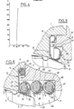
- the butterfly valve comprises a body 1 through which a substantially circular section of pipe 2 for the passage of the fluid.
- a shutter disc - or butterfly - 3 carrying two diametrically opposite ears 4.
- One of these ears 4 is linked in rotation to a control shaft 6 opening out of the body 1, while a shaft 7 forming a pivot, rotatably mounted in the body 1, is engaged in the other ear 4.
- the shutter 3 has on its periphery an annular spherical zone 8, offset laterally relative to the common axis XX of the shafts 6 and 7, and intended, in the closed position of the valve as shown in the figures, to cooperate with a sealing device 9 for closing the passage 2.
- the sealing device 9 comprises a seat 11 having an anchoring wing 12 fixed to the body 1, and an elastic annular structure 13, substantially toroidal, which projects inside the passage 2 for cooperate with the spherical zone 8 of the shutter 3.
- the anchoring wing 12 has a flat, substantially radial part, adjacent to the elastic wing 13, and inserted between a shoulder 14 of the body 1 and a ring 16 screwed onto the body 1.
- the anchoring wing 12 has, at the opposite of the elastic structure 13, a rolled part 17 housed in an annular recess 20 defined jointly by the shoulder 14 of the body 1 and the ring 16.
- the rolled part 17, which rests on three of the four sides of the the recess 20, of rectangular section, ensures the seal between the body 1 and the ring 16.
- the elastic structure 13 has an envelope 18 rolled in the opposite direction of the axis XX from the anchor wing 12.
- the anchor wing 12 and the envelope 18 form a single piece made of elastic metal sheet such as stainless steel.
- the section of the envelope 18 corresponds to a little more than three quarters of a circle.
- Inside the envelope 18, is housed an internal envelope 19 also made of elastic metal sheet, and rolled so as to be almost closed on itself, with the exception of a narrow annular slot 21.
- a helical spring 22, of circular axis is in turn housed in the internal envelope 19.
- the sealing device 9 also comprises a support element 23 by means of which the shutter structure 13. of the main seat 11 bears against the ring 16, opposite the axis XX.
- the elastic structure 13, substantially toroidal and the support element 23 are both mounted in a recess 24. formed in the internal face of the ring 16.
- This annular recess 24 has a radial face - or shoulder - 26 facing the body 1 and a cylindrical face 27 going from the face 26 to the seat 11.
- the support element 23 is interposed between the toroidal obturation structure 13 of the seat 11 and the radial face 26 of the annular clearance 24.
- the support element 23 which is of the type of an O-ring, comprises an outer casing 28 quite similar to the inner casing 19 of the seat 11, except that the diameter of its profile is close to that of the casing outer 18.
- the casing 28 has a convex outer surface against which the elastic structure 13, and more particularly the outer casing 18, bear on the ring 16 and the body 1.
- the annular slot 21 of the casing 28 is of preferably located between the circular generator of the envelope 28 closest to the cylindrical surface 27, and the circular generatrix of envelope 28 which is in contact with the main seat 11.
- a helical spring 29 of circular axis, similar to the spring 22 of the seat 11, is housed inside the casing 28 of the support element 23.
- the diameter of the turns of this spring is close to the diameter of the profile of the internal envelope 19 of the seat 11.
- the spherical zone 8 of the shutter 3 is in contact with the external envelope 18 of the elastic structure 13, according to a generator of the latter located between the anchoring wing 12 and the generator of contact with the support element 23.
- the presence of the seat 23 allows the valve to be exposed to high pressures (for example 45 ⁇ 10 5 Pa) while avoiding the plastic deformations of the seat 11, thanks, it seems, to the elastic deformation of the support element 23. Thus, such a valve can then be exposed to low pressures without the seal being compromised in the closed position. Furthermore, it seems that the elasticity of the seat 23 compensates for the effects of thermal expansion so as to keep the valve sealed and smooth to operate, regardless of the temperature of the fluid passing through it.
- FIG. 3 the torque in mN necessary for rotating the shutter 3 by action on the control shaft 6 is plotted on the abscissa. at the end of closing or at the beginning of opening, and on the ordinate, the pressure in Pa x 10 5 of the fluid, the valve of which controls the flow.
- the curve C1 was obtained by carrying out measurements on a valve of the kind of that of FIG. 2, 150 mm in diameter of the duct 2.
- the curve C2 relates to a similar valve but devoid of seat 23, and in which the casing 18 of the seat 11 is pressed directly against a concave annular surface formed in the ring such as 16, in accordance with FR-A-2331 725.
- the sealing device according to the invention allows a lower operating torque than that obtained according to the state of the art, this torque even being reduced approximately by half or more for higher pressures. at 45 x 10 5 Pa.
- the curve shown was obtained by carrying out measurements on a valve of the kind of that of FIG. 1, in which the passage 2 was 150 mm in diameter. This curve shows that the operating torque of the shutter is substantially constant up to more than 350 ° C.
- This sealing device will only be described with regard to its differences from that of FIG. 2. It comprises a seat 31 whose anchoring wing 12 is similar to that of FIG. 2, and the structure shutter 12 is similar to the outer casing 18 of the seat 2. Furthermore, the sealing device 31 comprises a support element 33 constituted by an annular rib with cross-section in a circular sector, formed on the radial face 36 of the annular recess 34 which has the internal wall of the ring 37 which, moreover, plays the same role as the ring 16 of FIG. 2.
- the embodiment shown in Figure 6, on the contrary is more particularly intended for relatively large diameter valves, or high quality valves whose cost may be higher.
- the seat 11 is similar to that of FIG. 2, except that an internal envelope 50 is inserted between the rolled part 17 of the anchoring wing 12 and the spring 15.
- the sealing device comprises two support elements 23 mounted in series between the elastic structure 13 of the seat 11 and the radial face of the annular clearance 44 formed in the ring 47, which moreover plays a role similar to that of the ring 16 of FIG. 2.
- the elements 23 are similar to the element 23 of FIG. 2, while the axial dimension of the clearance 44 is increased consequently compared to that of the clearance 24 of FIG. 2.
- the slot 21 of the external envelope of the adjacent element 23 at the main seat 11 occupies the same position as the slot 21 in FIG. 2, while the slot 21 of the other element 23 is located between the circular generators of contact with the first element 23 and the face 46 respectively, on the side of the axis of the duct 2.
- the f ente 21 of this element 23 is in a position approximately diametrically opposite to that of the first element 23.
- the seat 31 is similar to that of FIG. 5.
- the seat 31 can bear on the body 1 by means of two elements 53a, 53b, mounted in parallel between the casing 18 and the ring 57 screwed to the body 1.
- the elements 53a, 53b are similar to element 23, except that the diameter of their section is more reduced and that they do not contain helical springs.
- the element 53a has a torus diameter identical to that of the envelope 18 of the seat 31, while the other, 53b, is substantially larger, so that it is also slightly closer to the axis X-X.
- the recess 54 of the ring 57 has two radial faces 56a, 56b, both directed towards the axis X-X. and separated by a rim 56f.
- the elements 53a, 53b, which are supported one on the other, are each interposed between the envelope 18 and one of the faces 56a or 56b respectively, of the recess 54.
- the slot 21 of the element 53a is located between the circular generator of contact with the casing 18 and the circular generator of contact with the element 53b, while the slot 21 of the element 53b is located between the contact generator with the casing 18 and the generator closest to the cylindrical surface 58 of the recess 54.
- Figure 8 is similar to that of Figure 7, except that the elements 53a and 53b are not in contact with each other. In fact, the mean diameters of the toroids which they constitute have a greater difference between them than in FIG. 7. Furthermore, the radial surfaces 56a and 56b of the recess 54 are separated by a rib 56e ensuring the centering of the seat 53a relative to the axis of the duct 2.
- the slot 21 of the seat 53a is located between the annular generator in contact with the casing 18 and the generator closest to the rib 56e.
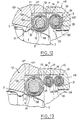
- FIG. 9 is more particularly intended for valves with a large passage diameter, for example 1 m or more.
- This example is similar to that of FIG. 8, except that these are four toric elements 53a, 53b, 53c, 53d which are interposed between the casing 18 and the ring 57 which is screwed to the body 1.
- the support of the elements 53a to 53d on the ring 57 takes place on four radial annular surfaces 56a, 56b, 56c, 56d of the recess 54, directed towards the axis X-X.
- the surfaces 56a and 56b are aligned and separated by a rib 56e which ensures the centering of the seat 53a relative to the axis of the duct 2.
- the surfaces 56b, 56c and 56d, which are staggered, are separated by flanges 56f and 56g which ensure the centering of the elements 53b and 53c respectively.
- the element 53d which has the largest diameter, is centered by the bottom 58 of the recess 54.
- the elements 53a to 53d have their slot 21 situated between the circular generatrix of contact with the envelope 18 and, as the case may be, the rib 56e, the edges 56f, 56g or the cylindrical surface 58.
- each element 53a, 53b or 53d closes slightly:
- the envelope 18 of the seat 31 is supported by a single seat 53 similar to the seat 53a or 53b of Figure 7.
- This seat 53 is as in the preceding Figures 7 to 9, pressing against a radial surface 56 of the clearance 54.
- the seat 53 is mounted in such a way that, in section as shown in FIG. 10, its point of contact A with the casing 18, is located on the perpendicular L to the surfaces of the spherical zone 8 and of the envelope 18, from point B of contact between these two surfaces.
- FIG. 11 is similar to that of FIG. 10, except that the sealing device here comprises two support elements 53a, 53b distributed on either side of the line L Each element 53a, 53b is resting against the ring 57 which for this purpose has two flat radial surfaces 56a, 56b.
- the seat 111 only comprises an elastic structure similar to that of FIG. 2 except that the external envelope 118 is substantially toroidal and completely closed on itself except for an annular slot. 121.
- the seat 111 is mounted in an annular recess 124 presented by the body 101 as an extension of the recess 24 of the ring 116.
- the outer casing 118 is pressed against the planar radial wall 125 of the recess 124, which is located substantially opposite the support element 23.
- a space may remain between the casing 118 and the cylindrical wall 127 of the clearance 124.
- the support element 23 is similar to that of FIG. 2, except that its profile may be of slightly reduced diameter and that an internal envelope 128 is interposed between the external envelope 28 and the spring 29.
- a flange 126 which separates the flat face 26 of the recess 24 from the duct 2 can reinforce the positioning of the support element 23.
- the slot 21 is arranged as in the embodiment of FIG. 2, and the slot 121 of the seat 111 is arranged in a manner substantially symmetrical to the slot 21 with respect to the contact plane between the seat 111 and the element 23.
- the winding of the outer casing 118 which causes a variation in the width of the slot 121, results in the winding of the outer casing 28 and the reduction in width of the slot 21.
- the seat 111 which is not in support only on the flat face 125 and the support element 23, centers itself on the shutter 3 when the latter arrives in the closed position, which reduces the risk of localized leakage to a certain portion from the periphery of the shutter.
- the invention also makes it possible to soften the operating torque and to increase the sealing performance of the valve.
- This sealing takes place, with the shutter 3, along the line P of contact between the shutter 3 and the casing 118, and with the body 101, along the line Q of contact between the casing 118 and the face radial 125 of the clearance 124, as well as along the line R of elastic contact between the envelopes 118 and 28, and along the line S of contact between the envelope 28 and the face 29 of the clearance 24.
- An additional O-ring (not shown, of a known type, can also be interposed between the body 101 and the ring 116.
- FIG. 13 The version of FIG. 13 is similar to that of FIG. 12, except that the annular clearance 24 of the ring 116 contains two support elements 123 arranged as in the embodiment of FIG. 6.
- This version is more particularly intended for large diameter and / or high quality valves.
- FIG. 14 will only be described with regard to its differences from FIG. 12.
- the support element 23 has a larger ring diameter and a smaller profile diameter than that of FIG. 12, and the cylindrical surfaces 27 and 127 of the recesses 24 and 124 are of larger diameter than those of the Figure 12.
- the main seat 111 is in oblique support against the radial wall 26 of the clearance 24.
- a second support element 123 is interposed between the seat 111 and the radial wall 125 of the clearance 124, symmetrically with the element 23 relative to the plane of the seat 111.
- the element 123 is analogous to the element except that the slot 21 relates to the part of the external envelope 28 facing the conduit 2 and extending between the line T of contact with the seat 111 and the line U of contact with face 125.
- this embodiment of the sealing device also allows the seat 111 to roll up and take place with reduced friction. It can therefore be seen that the invention lends itself to numerous applications, and the choice between one embodiment or the other may be made as a function of the compromise sought between the pressure which the valve can withstand and the desired softness of control over the control shaft 6. Other factors can also be considered, such as cost price, or diameter of flow of the fluid in the valve.
- the work in winding the shutter structure favored by the support element according to the invention makes it possible to limit the contact pressure in particular between the seat and the shutter.
- the deformations of the seat and of the support element or elements remain elastic, which gives the valve its good resistance to variations in temperature and pressure.
- the sealing device according to the invention is applicable to any type of valve which can receive a seat of the claimed type.
Landscapes
- Engineering & Computer Science (AREA)
- General Engineering & Computer Science (AREA)
- Mechanical Engineering (AREA)
- Lift Valve (AREA)
Claims (17)
Applications Claiming Priority (2)
| Application Number | Priority Date | Filing Date | Title |
|---|---|---|---|
| FR8026371A FR2496217A1 (fr) | 1980-12-12 | 1980-12-12 | Dispositif d'etancheite pour vanne |
| FR8026371 | 1980-12-12 |
Publications (2)
| Publication Number | Publication Date |
|---|---|
| EP0054473A1 EP0054473A1 (de) | 1982-06-23 |
| EP0054473B1 true EP0054473B1 (de) | 1985-06-26 |
Family
ID=9248977
Family Applications (1)
| Application Number | Title | Priority Date | Filing Date |
|---|---|---|---|
| EP81401933A Expired EP0054473B1 (de) | 1980-12-12 | 1981-12-04 | Ventilabdichtung |
Country Status (8)
| Country | Link |
|---|---|
| US (1) | US4477057A (de) |
| EP (1) | EP0054473B1 (de) |
| JP (1) | JPS608381B2 (de) |
| CA (1) | CA1160614A (de) |
| DE (1) | DE3171148D1 (de) |
| FR (1) | FR2496217A1 (de) |
| MX (1) | MX154577A (de) |
| ZA (1) | ZA818524B (de) |
Cited By (2)
| Publication number | Priority date | Publication date | Assignee | Title |
|---|---|---|---|---|
| DE3806912A1 (de) * | 1987-06-29 | 1989-01-19 | Akira Oshima | Dichtungssystem fuer ein fluegelventil |
| DE4424122A1 (de) * | 1994-07-08 | 1996-01-18 | Xomox Int Gmbh | Absperrklappe |
Families Citing this family (40)
| Publication number | Priority date | Publication date | Assignee | Title |
|---|---|---|---|---|
| JPS59141263U (ja) * | 1983-03-11 | 1984-09-20 | 株式会社巴技術研究所 | シ−トリング |
| JPS59141262U (ja) * | 1983-03-11 | 1984-09-20 | 株式会社巴技術研究所 | メタルシ−トリング |
| FR2559232B1 (fr) * | 1984-02-03 | 1986-08-22 | Marine Ind Petrole | Vanne a papillon spherique |
| FR2581728B1 (fr) * | 1985-05-10 | 1987-07-31 | Munzing Sa | Dispositif annulaire d'etancheite, notamment pour des vannes et robinets |
| JPS63130888A (ja) * | 1986-11-20 | 1988-06-03 | 日本建鐵株式会社 | 沓摺りの取付方法 |
| JPH01188772A (ja) * | 1988-01-21 | 1989-07-28 | Akira Oshima | バタフライ弁の正逆両圧シール装置 |
| US4848729A (en) * | 1988-02-01 | 1989-07-18 | Dresser Industries, Inc. | Valve seal |
| FR2636115B1 (fr) * | 1988-09-08 | 1990-10-19 | Commissariat Energie Atomique | Joint d'etancheite metallique a pression specifique tres elevee |
| FR2686136B1 (fr) * | 1992-01-15 | 1995-06-30 | Alsthom Velan | Vanne a joint metallique notamment vanne papillon. |
| US5433456A (en) * | 1992-12-18 | 1995-07-18 | The Advanced Products Company | Spring energized convoluted surface seal |
| DE4300191A1 (de) * | 1993-01-07 | 1994-07-14 | Klein Schanzlin & Becker Ag | Dichtung aus Metall |
| FR2721086B1 (fr) * | 1994-06-14 | 1996-07-12 | Commissariat Energie Atomique | Presse-étoupe à montage élastique des joints d'étanchéité. |
| CN1093236C (zh) * | 1996-04-18 | 2002-10-23 | 通用信号公司 | 双向阀密封机构 |
| US6120037A (en) * | 1997-05-20 | 2000-09-19 | Schmertz; John C. | Amplified pressure force seal |
| DE10251385A1 (de) * | 2002-11-01 | 2004-05-13 | Siemens Ag | Ventil |
| US6983940B2 (en) * | 2003-07-29 | 2006-01-10 | American Seal And Engineering Company, Inc. | Metallic seal |
| KR100729839B1 (ko) | 2006-04-19 | 2007-06-21 | 피케이밸브 주식회사 | 활하중 시트부 지지형 초저온 버터플라이밸브 |
| US7963503B2 (en) * | 2006-09-21 | 2011-06-21 | Fisher Controls International Llc | Metal seal with flexible insert |
| DE102007062681A1 (de) * | 2007-12-24 | 2009-06-25 | Man Turbo Ag | Dichtsegment sowie Dichtsegmentenanordnung |
| US8511972B2 (en) * | 2009-12-16 | 2013-08-20 | Siemens Energy, Inc. | Seal member for use in a seal system between a transition duct exit section and a turbine inlet in a gas turbine engine |
| CN102853093A (zh) * | 2011-06-30 | 2013-01-02 | 江苏神通阀门股份有限公司 | 一种双动式隔离阀 |
| US9611712B2 (en) * | 2012-02-09 | 2017-04-04 | Onesubsea Ip Uk Limited | Lip seal |
| WO2017011673A2 (en) * | 2015-07-14 | 2017-01-19 | Hartman Thomas A | Spring ring valve seat and butterfly valve with spring ring valve seat |
| CN106151543A (zh) * | 2016-07-22 | 2016-11-23 | 苏州纽威阀门股份有限公司 | 一种硬密封蝶阀 |
| WO2018022924A1 (en) * | 2016-07-28 | 2018-02-01 | Flowserve Management Company | Shutoff seal for high temperature pressure balance valve and related methods |
| US10309562B2 (en) * | 2017-07-18 | 2019-06-04 | Freudenberg Oil & Gas, Llc | Metal to metal wedge ring seal |
| JP6907807B2 (ja) * | 2017-08-22 | 2021-07-21 | 株式会社デンソー | 複合シールリング |
| CN107842628B (zh) * | 2017-11-28 | 2023-09-01 | 西铁阀门科技有限公司 | 双向压万向自动补偿阀座压板型阀门 |
| CN108019523B (zh) * | 2017-12-01 | 2024-01-30 | 中国船舶重工集团公司第七一九研究所 | 集成式杯形管节 |
| FR3079903B1 (fr) | 2018-04-04 | 2022-12-23 | Commissariat Energie Atomique | Assemblage d'etancheite metallique pour l'etancheite entre un arbre tournant et un bati fixe |
| CN108533760A (zh) * | 2018-05-29 | 2018-09-14 | 芜湖三花自控元器件有限公司 | 一种新型截止阀密封结构 |
| CN109185469B (zh) * | 2018-10-10 | 2024-06-21 | 中冶南方工程技术有限公司 | 能自锁的双向密封闸阀 |
| CN109210224B (zh) * | 2018-10-10 | 2024-06-21 | 中冶南方工程技术有限公司 | 双向密封闸阀 |
| CN110608290A (zh) * | 2019-10-23 | 2019-12-24 | 江苏神通阀门股份有限公司 | 一种可在线更换密封副的三偏心金属密封蝶阀结构 |
| US11467056B2 (en) | 2019-11-01 | 2022-10-11 | Saudi Arabian Oil Company | Sensing leak in a multi-seal sealing assembly with sensors |
| CN111173956B (zh) * | 2020-03-12 | 2025-07-29 | 四川苏克流体控制设备股份有限公司 | 一种高低温交变纯金属双向密封球阀 |
| CN112303259A (zh) * | 2020-11-23 | 2021-02-02 | 天津卡尔斯阀门股份有限公司 | 一种自动补偿蝶阀阀座密封结构 |
| CN113757397B (zh) * | 2021-10-09 | 2025-02-07 | 远大阀门集团有限公司 | 一种六偏心双向密封蝶阀 |
| CN114776827B (zh) * | 2022-04-12 | 2024-03-26 | 浙江贝尔控制阀门有限公司 | 一种改良型偏心旋转阀 |
| CN116557558B (zh) * | 2023-05-16 | 2023-09-29 | 建湖县鸿达阀门管件有限公司 | 一种175MPa防砂型平板阀 |
Citations (1)
| Publication number | Priority date | Publication date | Assignee | Title |
|---|---|---|---|---|
| FR2331725A1 (fr) * | 1975-11-14 | 1977-06-10 | Realmeca | Siege annulaire, notamment pour des vannes et robinets |
Family Cites Families (7)
| Publication number | Priority date | Publication date | Assignee | Title |
|---|---|---|---|---|
| FR2398940A1 (fr) * | 1977-07-26 | 1979-02-23 | Amri | Double joint torique flexible |
| US3250510A (en) * | 1964-02-18 | 1966-05-10 | Crane Co | Self-adjustable seats for butterfly valves or the like |
| US3563510A (en) * | 1969-08-06 | 1971-02-16 | Hills Mccanna Co | Valve sealed by calking ring anchored in support groove |
| CA1017314A (en) * | 1973-12-05 | 1977-09-13 | Werner K. Priese | Pressure loaded sealing arrangement |
| US4005848A (en) * | 1975-02-11 | 1977-02-01 | Fisher Controls Company, Inc. | Bidirectional pressure-assisted valve seal |
| BR7606565A (pt) * | 1975-10-02 | 1977-06-07 | Fisher Controls Co | Estrutura de vedador de valvula |
| US4247079A (en) * | 1979-09-06 | 1981-01-27 | Societe Meusienne De Realisations Mecaniques "Realmeca" | Annular valve seating |
-
1980
- 1980-12-12 FR FR8026371A patent/FR2496217A1/fr active Granted
-
1981
- 1981-12-04 DE DE8181401933T patent/DE3171148D1/de not_active Expired
- 1981-12-04 EP EP81401933A patent/EP0054473B1/de not_active Expired
- 1981-12-08 ZA ZA818524A patent/ZA818524B/xx unknown
- 1981-12-08 US US06/328,645 patent/US4477057A/en not_active Expired - Lifetime
- 1981-12-10 CA CA000391963A patent/CA1160614A/en not_active Expired
- 1981-12-11 JP JP56198779A patent/JPS608381B2/ja not_active Expired
- 1981-12-11 MX MX190587A patent/MX154577A/es unknown
Patent Citations (1)
| Publication number | Priority date | Publication date | Assignee | Title |
|---|---|---|---|---|
| FR2331725A1 (fr) * | 1975-11-14 | 1977-06-10 | Realmeca | Siege annulaire, notamment pour des vannes et robinets |
Cited By (3)
| Publication number | Priority date | Publication date | Assignee | Title |
|---|---|---|---|---|
| DE3806912A1 (de) * | 1987-06-29 | 1989-01-19 | Akira Oshima | Dichtungssystem fuer ein fluegelventil |
| DE4424122A1 (de) * | 1994-07-08 | 1996-01-18 | Xomox Int Gmbh | Absperrklappe |
| DE4424122C2 (de) * | 1994-07-08 | 1999-06-10 | Xomox Int Gmbh | Absperrklappe |
Also Published As
| Publication number | Publication date |
|---|---|
| DE3171148D1 (en) | 1985-08-01 |
| CA1160614A (en) | 1984-01-17 |
| FR2496217B1 (de) | 1983-03-04 |
| FR2496217A1 (fr) | 1982-06-18 |
| JPS57124166A (en) | 1982-08-02 |
| EP0054473A1 (de) | 1982-06-23 |
| ZA818524B (en) | 1982-10-27 |
| MX154577A (es) | 1987-10-02 |
| JPS608381B2 (ja) | 1985-03-02 |
| US4477057A (en) | 1984-10-16 |
Similar Documents
| Publication | Publication Date | Title |
|---|---|---|
| EP0054473B1 (de) | Ventilabdichtung | |
| BE1011130A3 (fr) | Dispositif d'obturation. | |
| EP2895773B1 (de) | Dichtung, insbesondere für eine unter druck stehende flüssigkeit | |
| CH640325A5 (fr) | Robinet a papillon. | |
| EP0166641A1 (de) | Abdichtung zum stromauf- und stromabwärts fluiddichten Verschliessen eines Absperrelementes | |
| EP0631072A1 (de) | Dichtung für Drehwelle | |
| CH631790A5 (fr) | Robinet a cartouche avec plaque rotative. | |
| FR2754583A1 (fr) | Vanne, notamment pour tubulure d'une ligne d'echappement | |
| CA2629789A1 (fr) | Procede et installation de controle non destructif par courants de foucault, a etalonnage automatique | |
| EP0884505B1 (de) | Vorrichtung mit einem drehbaren Hebel zur Bewegungsübertragung und Ventil mit einer solchen Vorrichtung | |
| EP2191093B1 (de) | Gerät zum drehen und festhalten einer wickelrolle und haushaltsautomatisierungsvorrichtung mit einem solchen gerät | |
| EP3974686A1 (de) | Metalldichtungssystem für dreifach exzentrisches drosselventil | |
| EP0722542A1 (de) | Schwimmsattel- scheibenbremse und stift dafür | |
| CH619522A5 (de) | ||
| CA2629798C (fr) | Vanne a clapet pour un systeme de refroidissement dans une turbomachine | |
| EP2986877B1 (de) | Ventil, insbesondere motorsteuerventil, mit einem dosierschieber und einem ablenkschieber | |
| FR2619430A1 (fr) | Dispositif d'accouplement et de freinage pouvant etre commute par un fluide compressible, notamment pneumatique | |
| CH655371A5 (fr) | Valve hydraulique. | |
| FR2581728A1 (fr) | Dispositif annulaire d'etancheite, notamment pour des vannes et robinets | |
| EP0179078B1 (de) | Hydraulische Turbine mit teilweise trockenlaufendem Laufrad und Injektor | |
| EP2013501B1 (de) | Kupplungslager | |
| FR2683289A1 (fr) | Joint pour vanne a papillon et vanne a papillon pourvue d'un tel joint. | |
| EP1938010B1 (de) | Wasserhahn mit kugelförmigem drehverschluss | |
| FR2832081A1 (fr) | Dispositif a peindre a element de maintien de rouleau de tenue fiabilisee | |
| CA2797332C (fr) | Robinet a joint metallique |
Legal Events
| Date | Code | Title | Description |
|---|---|---|---|
| PUAI | Public reference made under article 153(3) epc to a published international application that has entered the european phase |
Free format text: ORIGINAL CODE: 0009012 |
|
| 17P | Request for examination filed |
Effective date: 19811209 |
|
| AK | Designated contracting states |
Designated state(s): BE CH DE GB IT LI NL |
|
| ITCL | It: translation for ep claims filed |
Representative=s name: BARZANO' E ZANARDO ROMA S.P.A. |
|
| TCNL | Nl: translation of patent claims filed | ||
| DET | De: translation of patent claims | ||
| RAP1 | Party data changed (applicant data changed or rights of an application transferred) |
Owner name: GACHOT S.A. |
|
| ITF | It: translation for a ep patent filed | ||
| GRAA | (expected) grant |
Free format text: ORIGINAL CODE: 0009210 |
|
| AK | Designated contracting states |
Designated state(s): BE CH DE GB IT LI NL |
|
| REF | Corresponds to: |
Ref document number: 3171148 Country of ref document: DE Date of ref document: 19850801 |
|
| PLBE | No opposition filed within time limit |
Free format text: ORIGINAL CODE: 0009261 |
|
| STAA | Information on the status of an ep patent application or granted ep patent |
Free format text: STATUS: NO OPPOSITION FILED WITHIN TIME LIMIT |
|
| 26N | No opposition filed | ||
| PGFP | Annual fee paid to national office [announced via postgrant information from national office to epo] |
Ref country code: NL Payment date: 19861231 Year of fee payment: 6 |
|
| PG25 | Lapsed in a contracting state [announced via postgrant information from national office to epo] |
Ref country code: NL Effective date: 19880701 |
|
| NLV4 | Nl: lapsed or anulled due to non-payment of the annual fee | ||
| ITTA | It: last paid annual fee | ||
| REG | Reference to a national code |
Ref country code: CH Ref legal event code: NV Representative=s name: BOVARD AG PATENTANWAELTE |
|
| PGFP | Annual fee paid to national office [announced via postgrant information from national office to epo] |
Ref country code: GB Payment date: 19981120 Year of fee payment: 18 |
|
| PGFP | Annual fee paid to national office [announced via postgrant information from national office to epo] |
Ref country code: CH Payment date: 19981214 Year of fee payment: 18 |
|
| PGFP | Annual fee paid to national office [announced via postgrant information from national office to epo] |
Ref country code: BE Payment date: 19990205 Year of fee payment: 18 |
|
| PGFP | Annual fee paid to national office [announced via postgrant information from national office to epo] |
Ref country code: DE Payment date: 19990225 Year of fee payment: 18 |
|
| PG25 | Lapsed in a contracting state [announced via postgrant information from national office to epo] |
Ref country code: GB Free format text: LAPSE BECAUSE OF NON-PAYMENT OF DUE FEES Effective date: 19991204 |
|
| PG25 | Lapsed in a contracting state [announced via postgrant information from national office to epo] |
Ref country code: LI Free format text: LAPSE BECAUSE OF NON-PAYMENT OF DUE FEES Effective date: 19991231 Ref country code: CH Free format text: LAPSE BECAUSE OF NON-PAYMENT OF DUE FEES Effective date: 19991231 Ref country code: BE Free format text: LAPSE BECAUSE OF NON-PAYMENT OF DUE FEES Effective date: 19991231 |
|
| BERE | Be: lapsed |
Owner name: GACHOT S.A. Effective date: 19991231 |
|
| GBPC | Gb: european patent ceased through non-payment of renewal fee |
Effective date: 19991204 |
|
| PG25 | Lapsed in a contracting state [announced via postgrant information from national office to epo] |
Ref country code: DE Free format text: LAPSE BECAUSE OF NON-PAYMENT OF DUE FEES Effective date: 20001003 |