EP0054529B1 - Vibrateur pour compacter le sol et analogue - Google Patents
Vibrateur pour compacter le sol et analogue Download PDFInfo
- Publication number
- EP0054529B1 EP0054529B1 EP81850239A EP81850239A EP0054529B1 EP 0054529 B1 EP0054529 B1 EP 0054529B1 EP 81850239 A EP81850239 A EP 81850239A EP 81850239 A EP81850239 A EP 81850239A EP 0054529 B1 EP0054529 B1 EP 0054529B1
- Authority
- EP
- European Patent Office
- Prior art keywords
- shaft
- vibrator
- shafts
- hydraulic
- driven
- Prior art date
- Legal status (The legal status is an assumption and is not a legal conclusion. Google has not performed a legal analysis and makes no representation as to the accuracy of the status listed.)
- Expired
Links
- 239000002689 soil Substances 0.000 title claims abstract description 8
- 230000033001 locomotion Effects 0.000 claims abstract description 34
- 230000005540 biological transmission Effects 0.000 claims abstract description 14
- 230000001419 dependent effect Effects 0.000 claims abstract description 5
- 239000012530 fluid Substances 0.000 claims abstract description 4
- 238000010276 construction Methods 0.000 claims description 4
- 230000001360 synchronised effect Effects 0.000 abstract 1
- 239000010720 hydraulic oil Substances 0.000 description 10
- 239000003921 oil Substances 0.000 description 4
- 239000006096 absorbing agent Substances 0.000 description 2
- 238000002485 combustion reaction Methods 0.000 description 1
- -1 earth Substances 0.000 description 1
- 239000000463 material Substances 0.000 description 1
- 239000011435 rock Substances 0.000 description 1
- 239000004576 sand Substances 0.000 description 1
Images


Classifications
-
- E—FIXED CONSTRUCTIONS
- E02—HYDRAULIC ENGINEERING; FOUNDATIONS; SOIL SHIFTING
- E02D—FOUNDATIONS; EXCAVATIONS; EMBANKMENTS; UNDERGROUND OR UNDERWATER STRUCTURES
- E02D3/00—Improving or preserving soil or rock, e.g. preserving permafrost soil
- E02D3/02—Improving by compacting
- E02D3/046—Improving by compacting by tamping or vibrating, e.g. with auxiliary watering of the soil
- E02D3/074—Vibrating apparatus operating with systems involving rotary unbalanced masses
Definitions
- the present invention relates to a vibrator for vibrating soil.
- a vibrator for compacting crushed rock, earth, sand, street and road paving materials and so on by means of vibrations there is used a vibrator comprising a bottom plate supported by the soil and a vibratory element supported by the bottom plate for transmitting vibratory motions to the bottom plate.
- the vibratory element comprises two shafts rotatably driven by hydraulic motors in synchronism in opposite directions and each supporting one excentric weight. When driving the excentric weights in a rotational motion by means of the shafts there is imparted a vibratory motion to the vibratory element. By adjusting the relative position of the excentric weight it is possible to adjust the direction of the vibratory motion in a desired way.
- a drawback in previously known vibrators of the kind described above is that the selector device for providing the changing of the relative position of the excentric weights is complicated and difficult to control. Of course, this provides a restriction of the total manoeuvrability of the soil vibrator which in turn reduces the possibilities of operating the vibrator close to obstacles of differents kinds.
- a vibrator which by comprising an improved device for providing the changing of the relative position of the excentric weights presents an improved and simplified function and an improved manoeuvrability.
- the vibrator according to the invention is characterized in that the vibratory element comprises two hydraulic motors each connected with one shaft, that the shafts are connected with each other by means of a device for transmitting the rotational motion of one shaft to the other shaft, a portion of the motion transmission device connected with one of said shafts is rotatable in relation to said shaft between two engagement positions positioned at an angle distance from each other, and that the vibrator comprises a control device for supplying a main flow of hydraulic fluid to either the one or the other of the two hydraulic motors, the shafts being on each occasion driven by only the one or the other of the hydraulic motors, the one shaft being thereby driven directly and the other shaft being driven indirectly through the motion transmission device, the portion of the motion transmission device rotatable in relation to its shaft thereby taking different engagement positions dependent on the shaft being driven directly by the hydraulic motor connected with this shaft or indirectly by the hydraulic motor connected with the other shaft for providing different relative rotational positions of the shafts and the excentric weights supported thereby.
- control device can be formed as an electrically controlled selector valve which can be switched between two positions for supplying to either the one or the other hydraulic motor a main flow of hydraulic fluid in order to provide said adjustment or changing of the relative positions of the excentric weights.
- the motion transmission device comprises two gears which engage each other, one gear being fixedly connected with one shaft and the other being connected with the other shaft in such a way that it is rotatable between two engagement positions positioned at an angle distance from each other.
- the said construction of the vibrator solves the problem of self-synchronization present in vibrators of said kind.
- the self-synchronization provides that the excentric weights take a position in which they are running in phase with each other and do not take the desired relative position in which the vibratory motions have the desired direction.
- this self-synchronization will not appear as the hydraulic motor driven through the motion transmission device will provide a breaking action on the shaft connected therewith which in turn provides that the engagement positions which are required for obtaining the desired direction of the vibratory motions will be maintained on all occasions.
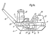
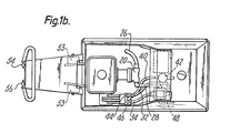
- Figs. 1 a, 1 band 1 c are a side view, a plan view and a front view, respectively, of a vibrator according to the invention.
- Figs. 2a and 2b are a plan view partly in section and a section along line II-II of Fig. 2a respectively of a vibratory unit included in the vibrator according to the invention.
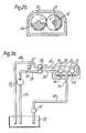
- Figs. 3a and 3b are schematic views of two different operative positions of a hydraulic drive system included in a vibrator according to the invention.
- Figs. 4a and 4b show portions of an embodiment of a vibratory unit included in the vibrator according to the invention.
- the vibrator according to the invention and shown in the drawings is intended for vibrating the soil and comprises a top portion 2 and a bottom portion 4 which are connected with each other by means of vibration absorbers 6 schematically shown.
- the bottom portion 4 comprises a bottom plate 8 and a vibratory element 10 supported thereby.
- the vibratory element 10 comprises two hydraulic motors 12 and 14 for driving the vibratory element.
- the top portion 2 comprises a manoeuvring handle 16, a combustion engine 18 for driving a hydraulic pump 20 which is connected with the hydraulic motors 12 and 14 for the operation thereof, the top portion 2 also comprises a hydraulic oil tank having a filling device 24.
- a suction line 26 From the hydraulic oil tank there extends a suction line 26 to the hydraulic pump 20.
- a main pressure line 28 extends from the hydraulic pump 20 to an electrically operated selector valve 30.
- From the selector valve 30 there extend a line 32 to the hydraulic motor 12 and a line 34 to the hydraulic motor 14.
- the hydraulic oil pressure can be supplied either to the hydraulic motor 12 through the line 32 or to the hydraulic motor 14 through the line 34.
- Return lines 36 and 38 extend from the hydraulic motors 12 and 14, respectively, and are connected with each other to a common return line 40 which extends back to the hydraulic oil tank 22 through a return oil filter 42.
- a check valve 44 is connected between the line 32 and the return line 36, and a check valve 46 is connected between the line 34 and the return line 38.
- a tank line 48 extends from the selector valve 30.
- a pressure limiting valve 52 is connected between the main pressure line 28 and the tank line 48.
- the manoeuvring handle 16 is connected with the top portion 2 of the vibrator by means of vibration absorbers 53 limiting the transmission of the vibratory motions of the vibrator to the handle.
- the manoeuvring handle 16 is provided with a control element for starting and stopping the vibratory motion and a control element 56 in the form of a pressure switch for switching the selector valve 30 between forward and backward movement of the vibrator.
- Figs. 2a and 2b are schematic views showing the construction of the vibratory unit 10 of the vibrator.
- the vibratory unit comprises a vibratory housing 60 in which two shafts 62 and 64 are rotatably journalled. Each shaft 62 and 64 supports an excentric weight 66 and 68, respectively. The excentric weights 66 and 68 are fixedly connected with the shaft belonging thereto.
- the shaft 62 supports a gear 70 unrotatably connected with the shaft.
- the shaft 64 supports a gear 72 which engages the gear 70.
- the gear 72 is rotatable in relation to the shaft 64 between two positions positioned at an angle distance of 180° from each other. In these positions there is an engagement between contact elements connected with the shaft and the gear, respectively.
- the construction of the contact elements is not shown in Figs.
- Switching of the selector valve 30 provides that the hydraulic oil pressure is supplied to the hydraulic motor 14 instead of to the hydraulic motor 12, in turn providing that the hydraulic motor 12 will rotate the shaft 64 so that the engagement between the contact portions of the shaft and the gear 72 is discontinued and is restored not until the shaft 64 and therewith the excentric weight 68 have been rotated over an angle of 180° from the position shown in Figs. 2a and 2b. In this new relative position between the excentric weights 68 and 66 the shaft 62 with its excentric weight 66 will be driven in synchronism with the shaft 64 and its excentric weight 68.
- Figs. 3a and 3b there is shown the hydraulic system of the vibrator in the two relative positions between the excentric weights 66 and 68 described above.
- the selector valve 30 is adjusted for directing hydraulic pressure oil from the hydraulic pump 20 and the pressure line 28 to the hydraulic motor 12 through the line 33. From the hydraulic motor 12 the hydraulic oil flows to the return line 36 and the return line 40 to the tank 22 through the oil filter 42. Thereby, the check valve 44 is in a closed position to direct the whole hydraulic oil flow through the hydraulic motor 12.
- the hydraulic motor 14 is driven by the hydraulic motor 12 through the gears 70 and 72 and the shafts 62 and 64.
- the hydraulic motor 12 acts as a pump and circulates hydraulic oil in the clockwise direction in the circuit constituted by the hydraulic motor 14, the line 38, the check valve 46 and back to the hydraulic motor 14.
- a restriction 74 in the line 40 providing substantially the same flow resistance as the check valve 46 and the hydraulic motor 14. In this position of balance of the pressure drops in the system there is no return flow to the tank 22 through the line 34 and the line 48.
- a pressure limiting valve 52 is provided between the pressure line 28 and the tank line 48.
- the pressure resistance in the pressure line 28 and/or the lines 32 and 34 is too high an overflow takes place from the pressure line 28 to the tank 22 through the pressure limiting valve 52 and the tank line 48.
- Fig. 3b the selector valve 30 is shown in a position for supplying hydraulic oil to the hydraulic motor 14 in order to drive this motor directly instead of directly driving the hydraulic motor 12.
- the excentric weights 66 and 68 take another relative position than was the case when the hydraulic system was operated in accordance with Fig. 3a.
- the hydraulic motor 12 is driven through the gears 70 and 72 and the shafts 62 and 64 for acting as a pump.
- the hydraulic system is operated in equivalent ways in other respects in the positions shown in Figs. 3a and 3b there is not required any detailed description of the operation in the position shown in Fig. 3b.
- Fig. 4a is a plan view on an enlarged scale of a portion of the vibratory element of the vibrator
- Fig. 4b is an end view of a detail of Fig. 4a.
- the shafts 62a and 64a are journalled in the housing 10a by means of conventional bearings 76.
- Each shaft 62a and 64a support an excentric weight 66a and 68a, respectively.
- a gear 70a is fixedly connected with the shaft 66a.
- a gear 72a is positioned on a stub shaft 78 on the shaft 64a.
- a sleeve 80 supporting a substantially semi-circular disc 82.
- the disc 82 is formed with semi-circular engagement surfaces 84 which are positioned at an angle distance of 180° from each other.
- the sleeve 80 including the disc 82 is unrotatably connected with the stub shaft 78, while the gear 72a is rotatably positioned on the sleeve 80.
- the gear 72a is provided with a pin 86 which is adapted to engage the engagement surfaces 84 of the disc 82.
- the vibrator according to the invention is extremely easy to operate because of the fact that the whole operation is provided by switching a selector valve which in a simple manner is operated electrically and that the hydraulic oil so to say provides an adjustment function by means of servo-action. Additionally it is a great advantage that the vibratory element can be positioned completely enclosed as the vibrator is often operated in a dusty and smokey atmosphere.
- the vibrator can be modified within the scope of the following claims.
- the vibrator with more than one vibratory element, the elements thereby being positioned so that the vibrator is manoevurable for turning in the sidewise directions.
- the selector valve 30 for manual operation instead of electric operation.
Landscapes
- Engineering & Computer Science (AREA)
- Structural Engineering (AREA)
- Life Sciences & Earth Sciences (AREA)
- General Life Sciences & Earth Sciences (AREA)
- Soil Sciences (AREA)
- Environmental & Geological Engineering (AREA)
- Agronomy & Crop Science (AREA)
- Mining & Mineral Resources (AREA)
- Paleontology (AREA)
- Civil Engineering (AREA)
- General Engineering & Computer Science (AREA)
- Apparatuses For Generation Of Mechanical Vibrations (AREA)
- Road Paving Machines (AREA)
- Soil Working Implements (AREA)
- Investigation Of Foundation Soil And Reinforcement Of Foundation Soil By Compacting Or Drainage (AREA)
Claims (8)
Priority Applications (1)
| Application Number | Priority Date | Filing Date | Title |
|---|---|---|---|
| AT81850239T ATE9109T1 (de) | 1980-12-12 | 1981-12-11 | Ruettelgeraet zum verdichten vom boden od. dgl. |
Applications Claiming Priority (2)
| Application Number | Priority Date | Filing Date | Title |
|---|---|---|---|
| SE8008759A SE443387B (sv) | 1980-12-12 | 1980-12-12 | Vibrator for markvibrering |
| SE8008759 | 1980-12-12 |
Publications (2)
| Publication Number | Publication Date |
|---|---|
| EP0054529A1 EP0054529A1 (fr) | 1982-06-23 |
| EP0054529B1 true EP0054529B1 (fr) | 1984-08-22 |
Family
ID=20342455
Family Applications (1)
| Application Number | Title | Priority Date | Filing Date |
|---|---|---|---|
| EP81850239A Expired EP0054529B1 (fr) | 1980-12-12 | 1981-12-11 | Vibrateur pour compacter le sol et analogue |
Country Status (4)
| Country | Link |
|---|---|
| EP (1) | EP0054529B1 (fr) |
| AT (1) | ATE9109T1 (fr) |
| DE (1) | DE3165713D1 (fr) |
| SE (1) | SE443387B (fr) |
Cited By (1)
| Publication number | Priority date | Publication date | Assignee | Title |
|---|---|---|---|---|
| DE4343865A1 (de) * | 1993-12-22 | 1995-07-13 | Ammann Duomat Verdichtung | Bodenverdichtungsgerät |
Families Citing this family (6)
| Publication number | Priority date | Publication date | Assignee | Title |
|---|---|---|---|---|
| DE3248474A1 (de) * | 1982-12-29 | 1984-07-12 | Weber Maschinentechnik Gmbh, 5928 Laasphe | Betaetigungsvorrichtung fuer die schaltkupplung umschaltbarer vibratoren von bodenverdichtern |
| SE453000B (sv) * | 1986-06-27 | 1988-01-04 | Dynapac Ab | Vibrationsplatta |
| SE513650C2 (sv) * | 1999-02-03 | 2000-10-16 | Svedala Compaction Equipment A | Vibratorplatta med ställbart avvibrerat handtag |
| GB2356235A (en) * | 1999-11-13 | 2001-05-16 | Benford Ltd | Compactor machine |
| CN109577142A (zh) * | 2018-12-05 | 2019-04-05 | 徐工集团工程机械股份有限公司 | 一种齿轮校正同步的垂直振动轮及其压路机 |
| DE102023118809A1 (de) * | 2023-07-17 | 2025-01-23 | Wacker Neuson Produktion GmbH & Co. KG | Bodenverdichtungsvorrichtung und phasenverstellbarer Unwuchterreger mit zwei angetriebenen Wellen |
Family Cites Families (6)
| Publication number | Priority date | Publication date | Assignee | Title |
|---|---|---|---|---|
| US2952193A (en) * | 1953-09-09 | 1960-09-13 | Frederick J Converse | Soil compacting machine |
| US2938438A (en) * | 1955-07-28 | 1960-05-31 | Baldwin Lima Hamilton Corp | Vibratory compactor |
| FR1473491A (fr) * | 1966-03-19 | 1967-03-17 | Zaklady Sprzetu Budowlanego Nr | Dispositif vibrateur, notamment pour des compacteurs lourds du sol |
| DE1634477A1 (de) * | 1966-03-24 | 1970-08-06 | Buckau Wolf Maschf R | Schalteinrichtung fuer einen Ruettelverdichter |
| US3505885A (en) * | 1968-03-12 | 1970-04-14 | Losenhausen Maschinenbau Ag | Vibration generators |
| US3670631A (en) * | 1970-12-28 | 1972-06-20 | Clark Equipment Co | Rotating vibrator |
-
1980
- 1980-12-12 SE SE8008759A patent/SE443387B/sv not_active IP Right Cessation
-
1981
- 1981-12-11 DE DE8181850239T patent/DE3165713D1/de not_active Expired
- 1981-12-11 AT AT81850239T patent/ATE9109T1/de not_active IP Right Cessation
- 1981-12-11 EP EP81850239A patent/EP0054529B1/fr not_active Expired
Cited By (1)
| Publication number | Priority date | Publication date | Assignee | Title |
|---|---|---|---|---|
| DE4343865A1 (de) * | 1993-12-22 | 1995-07-13 | Ammann Duomat Verdichtung | Bodenverdichtungsgerät |
Also Published As
| Publication number | Publication date |
|---|---|
| ATE9109T1 (de) | 1984-09-15 |
| SE8008759L (sv) | 1982-06-13 |
| SE443387B (sv) | 1986-02-24 |
| EP0054529A1 (fr) | 1982-06-23 |
| DE3165713D1 (en) | 1984-09-27 |
Similar Documents
| Publication | Publication Date | Title |
|---|---|---|
| US3814531A (en) | Articulated roller assembly | |
| EP0054529B1 (fr) | Vibrateur pour compacter le sol et analogue | |
| US4848845A (en) | Steerable self-regulating concrete cutting saw | |
| EP0251076B1 (fr) | Vibrateur à plaque | |
| US4577995A (en) | Mechanism for generating vibrations for a ground compacting machine | |
| US3895843A (en) | Road planing machine | |
| US3385119A (en) | Shaking or jarring mechanism | |
| AU582558B2 (en) | A material working machine | |
| CN110629642B (zh) | 自推进式建筑机械和用于对摊铺路面进行作业的方法 | |
| US2601277A (en) | Road machine | |
| US3899263A (en) | Compactor | |
| JPH07227125A (ja) | 自走草刈機 | |
| CA1132438A (fr) | Commande de neutralisation sur plateau oscillant de transmission hydrostatique | |
| US3550961A (en) | Mining machine | |
| CA1078238A (fr) | Vibrateur a plateau | |
| JPH11168904A (ja) | 苗移植機 | |
| US2243251A (en) | Road machine | |
| US3099942A (en) | Roller for road construction | |
| JP3198217B2 (ja) | 揺動型作業車両 | |
| JP3243127B2 (ja) | 揺動型作業車両 | |
| JP3529611B2 (ja) | 静流体圧伝動装置で走行する車両用のステアリングバルブ装置 | |
| JPS5923793Y2 (ja) | 暗渠掘削装置 | |
| SU1476060A1 (ru) | Устройство дл очистки каналов | |
| JPH0154482B2 (fr) | ||
| JPH09242014A (ja) | 操向機能を有する締固め機械 |
Legal Events
| Date | Code | Title | Description |
|---|---|---|---|
| PUAI | Public reference made under article 153(3) epc to a published international application that has entered the european phase |
Free format text: ORIGINAL CODE: 0009012 |
|
| AK | Designated contracting states |
Designated state(s): AT BE CH DE FR GB IT LU NL |
|
| 17P | Request for examination filed |
Effective date: 19821221 |
|
| ITF | It: translation for a ep patent filed | ||
| GRAA | (expected) grant |
Free format text: ORIGINAL CODE: 0009210 |
|
| AK | Designated contracting states |
Designated state(s): AT BE CH DE FR GB IT LI LU NL |
|
| REF | Corresponds to: |
Ref document number: 9109 Country of ref document: AT Date of ref document: 19840915 Kind code of ref document: T |
|
| REF | Corresponds to: |
Ref document number: 3165713 Country of ref document: DE Date of ref document: 19840927 |
|
| ET | Fr: translation filed | ||
| PG25 | Lapsed in a contracting state [announced via postgrant information from national office to epo] |
Ref country code: LU Free format text: LAPSE BECAUSE OF NON-PAYMENT OF DUE FEES Effective date: 19841231 |
|
| PLBE | No opposition filed within time limit |
Free format text: ORIGINAL CODE: 0009261 |
|
| STAA | Information on the status of an ep patent application or granted ep patent |
Free format text: STATUS: NO OPPOSITION FILED WITHIN TIME LIMIT |
|
| 26N | No opposition filed | ||
| ITTA | It: last paid annual fee | ||
| PGFP | Annual fee paid to national office [announced via postgrant information from national office to epo] |
Ref country code: GB Payment date: 19921208 Year of fee payment: 12 |
|
| PGFP | Annual fee paid to national office [announced via postgrant information from national office to epo] |
Ref country code: BE Payment date: 19921209 Year of fee payment: 12 |
|
| PGFP | Annual fee paid to national office [announced via postgrant information from national office to epo] |
Ref country code: FR Payment date: 19921218 Year of fee payment: 12 |
|
| PGFP | Annual fee paid to national office [announced via postgrant information from national office to epo] |
Ref country code: NL Payment date: 19921231 Year of fee payment: 12 |
|
| PGFP | Annual fee paid to national office [announced via postgrant information from national office to epo] |
Ref country code: AT Payment date: 19930112 Year of fee payment: 12 |
|
| PGFP | Annual fee paid to national office [announced via postgrant information from national office to epo] |
Ref country code: CH Payment date: 19930211 Year of fee payment: 12 |
|
| PGFP | Annual fee paid to national office [announced via postgrant information from national office to epo] |
Ref country code: DE Payment date: 19930223 Year of fee payment: 12 |
|
| PG25 | Lapsed in a contracting state [announced via postgrant information from national office to epo] |
Ref country code: GB Effective date: 19931211 Ref country code: AT Effective date: 19931211 |
|
| PG25 | Lapsed in a contracting state [announced via postgrant information from national office to epo] |
Ref country code: LI Effective date: 19931231 Ref country code: CH Effective date: 19931231 Ref country code: BE Effective date: 19931231 |
|
| BERE | Be: lapsed |
Owner name: VIPAC VIBRATOR A.B. Effective date: 19931231 |
|
| PG25 | Lapsed in a contracting state [announced via postgrant information from national office to epo] |
Ref country code: NL Effective date: 19940701 |
|
| GBPC | Gb: european patent ceased through non-payment of renewal fee |
Effective date: 19931211 |
|
| NLV4 | Nl: lapsed or anulled due to non-payment of the annual fee | ||
| PG25 | Lapsed in a contracting state [announced via postgrant information from national office to epo] |
Ref country code: FR Effective date: 19940831 |
|
| REG | Reference to a national code |
Ref country code: CH Ref legal event code: PL |
|
| PG25 | Lapsed in a contracting state [announced via postgrant information from national office to epo] |
Ref country code: DE Effective date: 19940901 |
|
| REG | Reference to a national code |
Ref country code: FR Ref legal event code: ST |