EP0054612A1 - Buse d'injection de carburant pour moteurs à combustion interne - Google Patents
Buse d'injection de carburant pour moteurs à combustion interne Download PDFInfo
- Publication number
- EP0054612A1 EP0054612A1 EP81106274A EP81106274A EP0054612A1 EP 0054612 A1 EP0054612 A1 EP 0054612A1 EP 81106274 A EP81106274 A EP 81106274A EP 81106274 A EP81106274 A EP 81106274A EP 0054612 A1 EP0054612 A1 EP 0054612A1
- Authority
- EP
- European Patent Office
- Prior art keywords
- injection
- needle
- pressure
- valve needle
- injection nozzle
- Prior art date
- Legal status (The legal status is an assumption and is not a legal conclusion. Google has not performed a legal analysis and makes no representation as to the accuracy of the status listed.)
- Ceased
Links
- 238000002347 injection Methods 0.000 title claims abstract description 52
- 239000007924 injection Substances 0.000 title claims abstract description 52
- 239000000446 fuel Substances 0.000 title claims abstract description 27
- 238000002485 combustion reaction Methods 0.000 title claims abstract description 4
- 238000007789 sealing Methods 0.000 claims description 8
- 239000007921 spray Substances 0.000 description 15
- 230000002411 adverse Effects 0.000 description 1
- 238000005507 spraying Methods 0.000 description 1
Images
Classifications
-
- F—MECHANICAL ENGINEERING; LIGHTING; HEATING; WEAPONS; BLASTING
- F02—COMBUSTION ENGINES; HOT-GAS OR COMBUSTION-PRODUCT ENGINE PLANTS
- F02M—SUPPLYING COMBUSTION ENGINES IN GENERAL WITH COMBUSTIBLE MIXTURES OR CONSTITUENTS THEREOF
- F02M61/00—Fuel-injectors not provided for in groups F02M39/00 - F02M57/00 or F02M67/00
- F02M61/16—Details not provided for in, or of interest apart from, the apparatus of groups F02M61/02 - F02M61/14
- F02M61/18—Injection nozzles, e.g. having valve seats; Details of valve member seated ends, not otherwise provided for
- F02M61/1806—Injection nozzles, e.g. having valve seats; Details of valve member seated ends, not otherwise provided for characterised by the arrangement of discharge orifices, e.g. orientation or size
- F02M61/182—Discharge orifices being situated in different transversal planes with respect to valve member direction of movement
-
- F—MECHANICAL ENGINEERING; LIGHTING; HEATING; WEAPONS; BLASTING
- F02—COMBUSTION ENGINES; HOT-GAS OR COMBUSTION-PRODUCT ENGINE PLANTS
- F02M—SUPPLYING COMBUSTION ENGINES IN GENERAL WITH COMBUSTIBLE MIXTURES OR CONSTITUENTS THEREOF
- F02M45/00—Fuel-injection apparatus characterised by having a cyclic delivery of specific time/pressure or time/quantity relationship
- F02M45/02—Fuel-injection apparatus characterised by having a cyclic delivery of specific time/pressure or time/quantity relationship with each cyclic delivery being separated into two or more parts
- F02M45/04—Fuel-injection apparatus characterised by having a cyclic delivery of specific time/pressure or time/quantity relationship with each cyclic delivery being separated into two or more parts with a small initial part, e.g. initial part for partial load and initial and main part for full load
- F02M45/08—Injectors peculiar thereto
- F02M45/086—Having more than one injection-valve controlling discharge orifices
-
- F—MECHANICAL ENGINEERING; LIGHTING; HEATING; WEAPONS; BLASTING
- F02—COMBUSTION ENGINES; HOT-GAS OR COMBUSTION-PRODUCT ENGINE PLANTS
- F02M—SUPPLYING COMBUSTION ENGINES IN GENERAL WITH COMBUSTIBLE MIXTURES OR CONSTITUENTS THEREOF
- F02M2200/00—Details of fuel-injection apparatus, not otherwise provided for
- F02M2200/46—Valves, e.g. injectors, with concentric valve bodies
Definitions
- the invention relates to a fuel injector according to the preamble of the main claim.
- the auxiliary needle serves only as a trailing needle, which separates the one injection point from the other during the first stroke of the valve needle, so that the fuel can only inject from the pressure chamber via one injection point.
- the trailing needle is then lifted off the seat, so that the second injection point is also connected to the pressure chamber for the injection.
- the control sequence of the injection points is thus controlled as a function of the stroke, pressure waves in the fuel causing the ven tilnadel can vibrate, which can possibly lead to an undesired connection of the second injection point to the pressure chamber even with small injection quantities.
- the fuel injection nozzle according to the invention with the characterizing features of the main claim has the advantage that the injection of large quantities via both injection points is clearly reduced in relation to the required pilot pressure of the fuel compared to the injection of small quantities via only one injection point. Since the auxiliary needle is loaded by a separate spring, its force can be chosen largely freely or can be designed according to the desired control pressure.
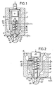
- FIG. 1 show that first exemplary embodiment in which the valve needle remains on the seat for the first low fuel pressure and only the auxiliary needle is actuated
- FIG. 2 shows the second exemplary embodiment in which the valve needle lifts off the seat even at the low fuel pressure.
- a valve needle 2 is guided in a nozzle body 1 in a radially sealing and axially displaceable manner. Via a pressure line 3 running in the nozzle body, fuel is delivered in a pressure chamber 4 from the fuel injection pump (not shown), which acts on the valve needle 2 in the opening direction against a closing force represented by an arrow.
- a coil spring normally serves as the closing force.
- the valve needle 2 is designed as a hollow needle, the end of which faces the closing spring is closed by a plug 5, on which a pressure pin 6 is arranged as an abutment for a spring plate of the closing spring / which is not known therein.
- An inner needle 7 works in the opening of the valve needle 2 facing away from this stopper 5.
- the inner space 8 delimited by the hollow needle 2, the stopper 5 and the inner needle 7 is always connected to the pressure chamber 4 by a bore 9, so that in the pressure chamber 4 and in the interior 8 there is the same pressure.
- the valve needle 2 has a sealing cone 10 which cooperates with a conical valve seat 11 of the nozzle body 1. This cone 11 merges into a blind hole 12 of the nozzle body 1, from which at least one first spray opening 13 branches off. At least one second spray opening 14 branches off from the seat cone 11, specifically downstream of the point at which the valve needle rests with its surface 10 on the seat 11.
- the inner needle 7 also has a sealing cone 21 that produces, in the illustrated rest position within the nozzle body 1, a V erbin- connection between the first injection opening 13 and the two-th injection port 14 and relieves the blind hole volume. This starting position of the inner needle 7 is determined by a spring 15 which is supported on the one hand on a shoulder 16 in the inner bore of the valve needle 2 and on the other hand at least indirectly on the valve needle 7. The valve needle 7 is loaded against the direction of flow.
- valve needle 7 in the rest position with a cone 17 g on a valve seat 18 on the valve needle 2 e-presses, whereby the first spray orifice 13 and the second injection port 14 are connected to each other within the nozzle body 1 .
- the pressure continues into the interior 8, so that the inflowing fuel lifts the valve needle 7 from the seat 18 and up. pushes the seat 11.
- the first spray opening 13 is separated from the second spray opening 14 and the interior 8 is connected to the second spray opening 14, so that an injection takes place via the latter.
- the valve needle 2 As soon as the amount of fuel delivered per unit of time increases, e.g. B. at higher speed or larger flow rate, the valve needle 2 is moved against the closing spring and lifts off the valve seat 11. As a result, the pressure chamber 4 is connected directly to the spray opening 1.4. After a certain stroke h has been covered, the inner needle 7 is taken along as a dragging member by the valve needle 2 after a shoulder 19 in the interior 8 strikes a spring plate 20 of the spring 15 of the inner needle. As a result, the inner needle 7 is lifted off the seat 11 again, so that the pressure chamber 4 is also connected directly to the first spray opening 13. For reasons of sealing and functional reliability and to coordinate the point in time at which the injection takes place via openings 13 and 14, h is always greater than h 1 .
- the inner needle 7 ' is guided in a radially sealing manner in the valve needle 2 and, like in the first example, connects the first spray opening 13' with the second spray opening 14 'in the starting position by the spring 15', within the nozzle body 1 '.
- the valve needle 7' is first pushed onto the seat 11 'due to the pressure which continues through the bore 9' into the interior 8 ', as a result of which the spray openings 13' and 14 ' be separated from each other.
- valve needle 2 When the pressure increases further, the valve needle 2 'then lifts off the seat 11', and the fuel under pressure passes from the pressure chamber 4 'to the second spray opening 14', via which it is injected. Only at higher pressure, for example due to higher speed or larger flow rate, the stroke h of the Ven tilnadel 2 'over the shoulder 19' of the spring plate 20 'and thus the inner needle 7 1 taken so that it lifts off the seat 11'. After the inner needle 7 'has been lifted off, the pressure chamber 4' is connected to both spray openings 13 'and 14', so that spraying is carried out via both spray openings.
- a sliding block 22 or another fixing device prevents the inner needle 7 1 from rotating, and the stroke h 1 of the inner needle 7' is less than h, whereby also, as in the first exemplary embodiment, the point in time or opening pressure is determined from which the injection takes place via both spray openings 13 'and 14'.
Landscapes
- Engineering & Computer Science (AREA)
- Chemical & Material Sciences (AREA)
- Combustion & Propulsion (AREA)
- Mechanical Engineering (AREA)
- General Engineering & Computer Science (AREA)
- Fuel-Injection Apparatus (AREA)
Applications Claiming Priority (2)
| Application Number | Priority Date | Filing Date | Title |
|---|---|---|---|
| DE19803048304 DE3048304A1 (de) | 1980-12-20 | 1980-12-20 | "kraftstoffeinspritzduese fuer brennkraftmaschinen" |
| DE3048304 | 1980-12-20 |
Publications (1)
| Publication Number | Publication Date |
|---|---|
| EP0054612A1 true EP0054612A1 (fr) | 1982-06-30 |
Family
ID=6119828
Family Applications (1)
| Application Number | Title | Priority Date | Filing Date |
|---|---|---|---|
| EP81106274A Ceased EP0054612A1 (fr) | 1980-12-20 | 1981-08-12 | Buse d'injection de carburant pour moteurs à combustion interne |
Country Status (4)
| Country | Link |
|---|---|
| US (1) | US4407457A (fr) |
| EP (1) | EP0054612A1 (fr) |
| JP (1) | JPS57129253A (fr) |
| DE (1) | DE3048304A1 (fr) |
Cited By (3)
| Publication number | Priority date | Publication date | Assignee | Title |
|---|---|---|---|---|
| EP0978649A3 (fr) * | 1998-08-06 | 2003-01-29 | Siemens Aktiengesellschaft | Buse d'injection de combustible |
| EP1744050A1 (fr) * | 2005-07-13 | 2007-01-17 | Delphi Technologies, Inc. | Buse d'injection |
| EP1744051A1 (fr) * | 2005-07-13 | 2007-01-17 | Delphi Technologies, Inc. | Buse d'injection |
Families Citing this family (21)
| Publication number | Priority date | Publication date | Assignee | Title |
|---|---|---|---|---|
| DE3236046C2 (de) * | 1982-09-29 | 1986-03-20 | Daimler-Benz Ag, 7000 Stuttgart | Kraftstoffeinspritzdüse für Brennkraftmaschinen |
| US5058549A (en) * | 1988-02-26 | 1991-10-22 | Toyota Jidosha Kabushiki Kaisha | Fuel swirl generation type fuel injection valve and direct fuel injection type spark ignition internal combustion engine |
| US4974565A (en) * | 1988-02-26 | 1990-12-04 | Toyota Jidosha Kabushiki Kaisha | Fuel swirl generation type fuel injection valve and direct fuel injection type spark ignition internal combustion engine mounted with the fuel injection valve |
| DE4214646A1 (de) * | 1992-05-02 | 1993-11-04 | Bosch Gmbh Robert | Kraftstoffeinspritzduese fuer vor- und haupteinspritzung |
| JP3625106B2 (ja) * | 1996-07-29 | 2005-03-02 | 三菱電機株式会社 | 燃料噴射弁 |
| GB9709678D0 (en) * | 1997-05-14 | 1997-07-02 | Lucas Ind Plc | Fuel injector |
| DE69922087T2 (de) | 1998-06-24 | 2005-12-01 | Delphi Technologies, Inc., Troy | Brennstoffeinspritzdüse |
| GB9904938D0 (en) * | 1999-03-04 | 1999-04-28 | Lucas Ind Plc | Fuel injector |
| GB9914644D0 (en) * | 1999-06-24 | 1999-08-25 | Lucas Ind Plc | Fuel injector |
| EP1091117B1 (fr) * | 1999-10-06 | 2008-04-02 | Delphi Technologies, Inc. | Injecteur de carburant |
| DE10034445A1 (de) | 2000-07-15 | 2002-01-24 | Bosch Gmbh Robert | Brennstoffeinspritzventil |
| DE10034444A1 (de) | 2000-07-15 | 2002-01-24 | Bosch Gmbh Robert | Brennstoffeinspritzventil |
| DE10056039A1 (de) | 2000-11-11 | 2002-05-16 | Bosch Gmbh Robert | Brennstoffeinspritzventil |
| JP3578105B2 (ja) * | 2001-04-12 | 2004-10-20 | トヨタ自動車株式会社 | 燃料噴射装置 |
| EP1637730B1 (fr) * | 2004-09-17 | 2014-04-16 | Delphi International Operations Luxembourg S.à r.l. | Injecteur de combustible et procédé de fabrication |
| CN100422545C (zh) * | 2004-12-15 | 2008-10-01 | 浙江飞亚电子有限公司 | 一种喷油嘴 |
| ATE487048T1 (de) * | 2005-03-04 | 2010-11-15 | Delphi Tech Holding Sarl | Einspritzdüse |
| CN103392065B (zh) * | 2011-02-23 | 2016-04-20 | 丰田自动车株式会社 | 燃料喷射阀 |
| US9562505B2 (en) * | 2013-06-11 | 2017-02-07 | Cummins Inc. | System and method for control of fuel injector spray |
| NL1041155B1 (nl) * | 2015-01-23 | 2017-01-05 | Johan Willem Maria Nooijen Paul | Dualfuel injector en methodes. |
| DE102019103511A1 (de) * | 2019-02-12 | 2020-08-13 | Liebherr-Components Deggendorf Gmbh | Düse für einen Kraftstoffinjektor |
Citations (2)
| Publication number | Priority date | Publication date | Assignee | Title |
|---|---|---|---|---|
| DE1284687B (de) * | 1967-10-18 | 1968-12-05 | Bosch Gmbh Robert | Kraftstoffeinspritzventil fuer Vor- und Haupteinspritzung |
| DE2147719A1 (de) * | 1971-09-24 | 1973-03-29 | Bosch Gmbh Robert | Kraftstoffeinspritzventil |
Family Cites Families (4)
| Publication number | Priority date | Publication date | Assignee | Title |
|---|---|---|---|---|
| US2410946A (en) * | 1943-04-10 | 1946-11-12 | Caterpillar Tractor Co | Fuel injection mechanism |
| US3446440A (en) * | 1967-06-14 | 1969-05-27 | Int Harvester Co | Double injection system with one nozzle |
| DE2711390A1 (de) * | 1977-03-16 | 1978-09-21 | Bosch Gmbh Robert | Kraftstoffeinspritzduese |
| JPS586423B2 (ja) * | 1977-06-10 | 1983-02-04 | ケイディディ株式会社 | 交換台における呼の配布方式 |
-
1980
- 1980-12-20 DE DE19803048304 patent/DE3048304A1/de not_active Withdrawn
-
1981
- 1981-08-12 EP EP81106274A patent/EP0054612A1/fr not_active Ceased
- 1981-11-30 US US06/326,091 patent/US4407457A/en not_active Expired - Fee Related
- 1981-12-18 JP JP56203815A patent/JPS57129253A/ja active Pending
Patent Citations (2)
| Publication number | Priority date | Publication date | Assignee | Title |
|---|---|---|---|---|
| DE1284687B (de) * | 1967-10-18 | 1968-12-05 | Bosch Gmbh Robert | Kraftstoffeinspritzventil fuer Vor- und Haupteinspritzung |
| DE2147719A1 (de) * | 1971-09-24 | 1973-03-29 | Bosch Gmbh Robert | Kraftstoffeinspritzventil |
Cited By (5)
| Publication number | Priority date | Publication date | Assignee | Title |
|---|---|---|---|---|
| EP0978649A3 (fr) * | 1998-08-06 | 2003-01-29 | Siemens Aktiengesellschaft | Buse d'injection de combustible |
| EP1744050A1 (fr) * | 2005-07-13 | 2007-01-17 | Delphi Technologies, Inc. | Buse d'injection |
| EP1744051A1 (fr) * | 2005-07-13 | 2007-01-17 | Delphi Technologies, Inc. | Buse d'injection |
| US7744017B2 (en) | 2005-07-13 | 2010-06-29 | Delphi Technologies Holding S.Arl | Injection nozzle |
| US7871021B2 (en) | 2005-07-13 | 2011-01-18 | Delphi Technologies Holding S.Arl | Injection nozzle |
Also Published As
| Publication number | Publication date |
|---|---|
| US4407457A (en) | 1983-10-04 |
| DE3048304A1 (de) | 1982-07-29 |
| JPS57129253A (en) | 1982-08-11 |
Similar Documents
| Publication | Publication Date | Title |
|---|---|---|
| EP0054612A1 (fr) | Buse d'injection de carburant pour moteurs à combustion interne | |
| DE69010061T2 (de) | Brennstoffeinspritzeinrichtung für Dieselmotoren. | |
| DE2749378A1 (de) | Kraftstoffeinspritzduese | |
| EP1395744B1 (fr) | Appareil d'injection de carburant pour moteurs a combustion, en particulier injecteur de type common rail, systeme d'alimentation en carburant et moteur a combustion | |
| DE4440182C2 (de) | Kraftstoffeinspritzventil für Brennkraftmaschinen | |
| DE3844489A1 (de) | Kraftstoffeinspritzvorrichtung | |
| EP0688950B1 (fr) | Système d'injection de carburant | |
| DE2833431A1 (de) | Kraftstoffeinspritzduese | |
| EP1346143A1 (fr) | Soupape d'injection de carburant destinee a des moteurs a combustion interne | |
| DE19611963A1 (de) | Modulierende Strömungsumleitung für eine Brennstoffeinspritzvorrichtung | |
| DE19941688C2 (de) | Einspritzeinrichtung für eine Brennkraftmaschine mit Direkteinspritzung | |
| EP0220207B1 (fr) | Injecteur de carburant pour moteurs a combustion interne | |
| DE3734587A1 (de) | Kraftstoff-einspritzduese fuer brennkraftmaschinen | |
| EP0135872B1 (fr) | Injecteur de combustible pour moteurs à combustion interne | |
| DD139739A1 (de) | Kraftstoff-einspritzduese | |
| DE3928912A1 (de) | Kraftstoffeinspritzduese fuer brennkraftmaschinen | |
| DE3113755C2 (de) | Drosselzapfendüse zur Kraftstoffeinspritzung in den Brennraum einer Brennkraftmaschine | |
| DE2726300A1 (de) | Kraftstoffeinspritzduese | |
| DE10160490B4 (de) | Kraftstoff-Einspritzvorrichtung, Kraftstoffsystem sowie Brennkraftmaschine | |
| DE2706374A1 (de) | Brennstoffeinspritzventil fuer brennkraftmaschinen | |
| DE19623581A1 (de) | Kraftstoffeinspritzventil für Brennkraftmaschinen | |
| DE3032735A1 (de) | Verfahren und kraftstoffeinspritzduese zur geteuerten kraftstoffeinspritzung bei brennkraftmaschinen | |
| DE3118485C2 (de) | Kraftstoffeinspritzdüse für Brennkraftmaschinen | |
| EP1067284A1 (fr) | Soupape d'injection de combustible | |
| AT394761B (de) | Kraftstoff-einspritzduese fuer brennkraftmaschinen |
Legal Events
| Date | Code | Title | Description |
|---|---|---|---|
| PUAI | Public reference made under article 153(3) epc to a published international application that has entered the european phase |
Free format text: ORIGINAL CODE: 0009012 |
|
| 17P | Request for examination filed |
Effective date: 19810812 |
|
| AK | Designated contracting states |
Designated state(s): DE FR GB |
|
| STAA | Information on the status of an ep patent application or granted ep patent |
Free format text: STATUS: THE APPLICATION HAS BEEN REFUSED |
|
| 18R | Application refused |
Effective date: 19830823 |
|
| RIN1 | Information on inventor provided before grant (corrected) |
Inventor name: SEIFERT, KURT |