EP0054735A2 - Dispositif de fabrication de rouleaux de bandes formées à partir de feuilles souples imbriqueés - Google Patents
Dispositif de fabrication de rouleaux de bandes formées à partir de feuilles souples imbriqueés Download PDFInfo
- Publication number
- EP0054735A2 EP0054735A2 EP81109438A EP81109438A EP0054735A2 EP 0054735 A2 EP0054735 A2 EP 0054735A2 EP 81109438 A EP81109438 A EP 81109438A EP 81109438 A EP81109438 A EP 81109438A EP 0054735 A2 EP0054735 A2 EP 0054735A2
- Authority
- EP
- European Patent Office
- Prior art keywords
- belt
- conveyor
- rollers
- workpieces
- scale
- Prior art date
- Legal status (The legal status is an assumption and is not a legal conclusion. Google has not performed a legal analysis and makes no representation as to the accuracy of the status listed.)
- Granted
Links
Images


Classifications
-
- B—PERFORMING OPERATIONS; TRANSPORTING
- B65—CONVEYING; PACKING; STORING; HANDLING THIN OR FILAMENTARY MATERIAL
- B65H—HANDLING THIN OR FILAMENTARY MATERIAL, e.g. SHEETS, WEBS, CABLES
- B65H29/00—Delivering or advancing articles from machines; Advancing articles to or into piles
- B65H29/006—Winding articles into rolls
-
- B—PERFORMING OPERATIONS; TRANSPORTING
- B65—CONVEYING; PACKING; STORING; HANDLING THIN OR FILAMENTARY MATERIAL
- B65H—HANDLING THIN OR FILAMENTARY MATERIAL, e.g. SHEETS, WEBS, CABLES
- B65H29/00—Delivering or advancing articles from machines; Advancing articles to or into piles
- B65H29/66—Advancing articles in overlapping streams
-
- B—PERFORMING OPERATIONS; TRANSPORTING
- B65—CONVEYING; PACKING; STORING; HANDLING THIN OR FILAMENTARY MATERIAL
- B65H—HANDLING THIN OR FILAMENTARY MATERIAL, e.g. SHEETS, WEBS, CABLES
- B65H5/00—Feeding articles separated from piles; Feeding articles to machines
- B65H5/24—Feeding articles in overlapping streams, i.e. by separation of articles from a pile
-
- B—PERFORMING OPERATIONS; TRANSPORTING
- B65—CONVEYING; PACKING; STORING; HANDLING THIN OR FILAMENTARY MATERIAL
- B65H—HANDLING THIN OR FILAMENTARY MATERIAL, e.g. SHEETS, WEBS, CABLES
- B65H5/00—Feeding articles separated from piles; Feeding articles to machines
- B65H5/28—Feeding articles stored in rolled or folded bands
-
- B—PERFORMING OPERATIONS; TRANSPORTING
- B65—CONVEYING; PACKING; STORING; HANDLING THIN OR FILAMENTARY MATERIAL
- B65H—HANDLING THIN OR FILAMENTARY MATERIAL, e.g. SHEETS, WEBS, CABLES
- B65H2301/00—Handling processes for sheets or webs
- B65H2301/40—Type of handling process
- B65H2301/41—Winding, unwinding
- B65H2301/419—Winding, unwinding from or to storage, i.e. the storage integrating winding or unwinding means
- B65H2301/4192—Winding, unwinding from or to storage, i.e. the storage integrating winding or unwinding means for handling articles of limited length in shingled formation
- B65H2301/41922—Winding, unwinding from or to storage, i.e. the storage integrating winding or unwinding means for handling articles of limited length in shingled formation and wound together with single belt like members
- B65H2301/419225—Several belts spaced in axis direction
-
- B—PERFORMING OPERATIONS; TRANSPORTING
- B65—CONVEYING; PACKING; STORING; HANDLING THIN OR FILAMENTARY MATERIAL
- B65H—HANDLING THIN OR FILAMENTARY MATERIAL, e.g. SHEETS, WEBS, CABLES
- B65H2701/00—Handled material; Storage means
- B65H2701/10—Handled articles or webs
- B65H2701/19—Specific article or web
- B65H2701/191—Bags, sachets and pouches or the like
Definitions
- the invention relates to a device for producing scale tape rolls from flaky flat flexible objects, such as sacks or bag workpieces, placed one above the other on a conveyor belt, with a winding core mounted in the machine frame, on which at least one holding tape pulled off from a supply roll, which is seen from above when the scale tape is wound up holding it over this, is fastened, with a belt conveyor feeding the workpieces, which consists of a frame carrying rollers at least at opposite ends, which is pivotable about the axis of the first roller and a driven via the rollers endless conveyor belt is running, comprising means for queuing the frame to the winding core or the forming on this S chuppenbandrolle to drive it through the endless conveyor belt and a shingled the superposed objects the belt conveyor feeding conveying direction.
- the imbricated superposed flat articles are rt In one known from DE-OS known device 25 44135 this A wound in the formation to a flaking roll of tape as they are passed from the feeding conveyor at the same time the forming shed tape roll driving belt conveyor.
- malfunctions or irregularities in the partially overlapping placement of the objects or during the transport of the scale band formed in this way can lead to different lengths of overlap of the objects, which have a disruptive effect when winding the scale band to form a scale band roll and lead to non-round rolls can.
- this object is achieved in that a device detecting the distance of the front or rear edges of the overlapping workpieces on the feeding conveyor device and a control device are provided which, according to the determined deviations of the distances from the desired distance, drive the motor for the conveyor belt of the belt conveyor switch on or switch off and / or let it run at suitably adjusted different speeds.
- a so-called rotary feeder is provided for transferring flat objects stacked in packages, such as sacks or bag workpieces, into a shingled formation, the transport rollers of which are provided with suction cups and driven by planetary gears like gears, remove the workpieces from the stack individually and in the Insert the desired overlap length into the feed gap of a conveying device.
- the rotary feeder used according to the invention can be of a known construction, as described for example in DE-PS 900 815 and 12 77 655.
- a further embodiment of the invention provides that two swivel arms are mounted in a longitudinally displaceable manner on an axis arranged transversely to the belt conveyor. which each have a winding core receiving pins at their ends.
- the swivel arms can be easily and quickly pushed back and forth in such a way that one pin is in the winding position while the other is outside the belt conveyor, so that the finished wound scale roll can be removed and a new winding core can be put on.
- the formed scale belt roll cannot be stopped suddenly and set in rotation again. Nevertheless, the drive of the conveyor belt adapted to different overlap lengths leads to an equalization of the overlap lengths, which leads to an improved winding quality.
- the drive roller shaft for the conveyor belt is expediently connected to a pulse generator which emits electrical pulses corresponding to predetermined rotation angles of the shaft, which are counted by a counter which can be set to a desired number, the device scanning the workpiece edges with the detection of each workpiece edge the counter back to zero sets, the counter switches off the drive motor of the drive roller shaft when the set number is reached and the motor is only switched on again when the counter is reset by the scanning device.
- the device known from DE-OS 25 44 135 provides for the conveying device conveying the shingled sacks one above the other with two switches arranged one behind the other in the conveying direction to be provided, which in turn leads the sacks dropped onto these in scale formation to one of two winding stations.
- the known device is expensive in that two complete winding stations must be provided.
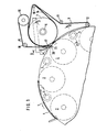
- the rotary feeder shown in Fig. 1 corresponds in its basic structure to the devices known from DE-PS 900 815 and 12 77 655, so that the description of details can be dispensed with.
- the rotary feeder has two end disks in which the rolling bodies 2 forming the transport rollers are mounted.
- Support rollers 5 are provided to support the workpieces 4. Since the workpieces 4 are not gripped by grippers and forwarded with them for further processing, a shaft 6 with transport disks 7 is provided instead of a gripper shaft, next to which further disks 8 are arranged, over which belts 9 run. To better grasp the workpieces coming from the rolling bodies 2, the belts 9 are guided over further rollers 10 to 12. In order to support the belts 9, 5 additional loose-running support rollers 16 are arranged in addition to the support rollers 5. In addition to the belts 9, further belts 14 are provided which run over the transport disks 7 and the rollers 10. The scale which forms on the transport disks 7 is guided on the outside by guide belts 15 which run over rollers 17 to 19.
- belts 15 run over the sufficiently wide rollers 18, 19 belts 20, which, however, are guided in the area of the rotary feeder via rollers 21 which lie within the circumference of the rolling body 2, so that the incoming workpiece start away from the rotary feeder and to the Transport discs 7 is passed.
- the scale is formed when the speed of the end disks 1 is in a suitable relationship with the speed of the rolling elements 2, that is to say is matched accordingly.
- the scale as shown in Fig. 4, is fed to the bag winder. Since the scale spacing of the incoming workpieces may vary, a device for the same scale spacing is provided so that a uniformly wound supply roll can be formed.
- a pressure roller 25 is provided on the scale.
- the scale is driven at a relatively high speed and at great distances.
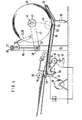
- the scale is scanned by the feeler. 26 thrown onto an endless conveyor belt 28 formed from individual belts, which runs over the rollers 29 to 34, which are rotatably mounted in a pivotable frame 35.
- the drive roller 36 is also attached to the frame 35, via which the strands are returned to the rollers 29.
- the frame 35 is pivotally mounted about the axis of the rollers 31 and is supported, for example, under the supply roller 37 to be wound by pneumatic cylinders 38, which have the task of tracking the frame 35 of the supply roller 37 in order to avoid out-of-roundness of the supply roller 37 which occurs during winding can compensate.
- a supply shaft 39 is provided on floor-mounted storage, from which retaining straps 40 are pulled, which are wound up in layers in a known manner with the workpieces on the supply roll 37.
- the axis of the drive roller 36 is equipped with a rotary pulse generator 41, the pulses of which are input to a counter 42.
- the counter 42 and the drive motor, not shown, of the drive roller 36 are electrically connected to the intermediate circuit 27.
- the counter 42 can be set to a predetermined number and is switched so that the drive motor is stopped after reaching this number.
- the predetermined number is chosen to be somewhat larger than the intended scale spacing.
- the sensor 42 is reset to zero when a workpiece end passes by the sensor 26. If there is no workpiece, so that the counter 42 reaches the predetermined number, the conveyor belt 28 is stopped and it only starts up again after the next workpiece has run through. Therefore, approximately the same scale distance is achieved on the conveyor belt 28.
- the core 45 of the supply roll 37 is held by a pin 46 which is fastened in the free end of a lever 47.
- the other end of the lever 47 is rotatably mounted on a bush 48 together with a second lever arm 49.
- the lever arm 49 carries a pin 50 corresponding to the pin 46 on its free end, but which extends in the opposite direction.
- Pressure medium cylinders 51, 52 are articulated to the lever arms 47 and 49, with which they or the supply roll 37 can be lowered onto the conveyor belt 28 and raised from there.
- the bushing 48 is smoothly and longitudinally displaceably mounted on an axis 53 which is fastened in a stand 54 arranged on both sides next to the conveyor belt 28.
- a guide part 55 is connected to the bushing 48 by a web 56.
- a roller 57 is loosely rotatably mounted on the guide part 55 and runs in a U-iron 58 which connects the two stands 54.
- the free ends of the pressure medium cylinders 51, 52 are articulated on the guide part 56.
- the bushing 48 can now be moved as desired with the levers 47, 49, so that the pin 46 is above the conveyor belt 28 and the pin 50 is outside the winding area. While a new supply roll 37 is being wound on the pin 46, the finished supply roll can be removed from the pin 50 and a new core 45 can be prepared. After completion of the supply roll 37 on the pin 46, it is lifted off the conveyor belt 28 by means of the pressure medium cylinder 51 and the bushing 48 is moved into its other extreme position, and the supply roll 37 is lowered on the hall floor and pulled
- the pressure medium cylinders 51, 52 connecting the levers 47, 49 to the slide-shaped guide part 55 are concerned hydraulic piston-cylinder units, while the conveyor belts running over the frame-shaped frame 35 are pressed by a pneumatic cylinder 38 against the winding core or the forming scale roller 37.
- the pneumatic cylinder 38 has a stroke of approximately 100 mm and is held in its central position by the fact that the hydraulic cylinders 51, 52 raise the levers 47, 49 in accordance with the winding progress.
- the hydraulic cylinders 51, 52 can be operated in that the pneumatic cylinder is provided with a limit switch.
- the pneumatic cylinder 38 has good resilient properties, so that it is able to compensate for out-of-roundness of the scale roller 37 that is being formed.
Landscapes
- Engineering & Computer Science (AREA)
- Mechanical Engineering (AREA)
- Making Paper Articles (AREA)
- Replacement Of Web Rolls (AREA)
- Discharge By Other Means (AREA)
- Separation, Sorting, Adjustment, Or Bending Of Sheets To Be Conveyed (AREA)
Applications Claiming Priority (2)
| Application Number | Priority Date | Filing Date | Title |
|---|---|---|---|
| DE3048721 | 1980-12-23 | ||
| DE3048721 | 1980-12-23 |
Publications (3)
| Publication Number | Publication Date |
|---|---|
| EP0054735A2 true EP0054735A2 (fr) | 1982-06-30 |
| EP0054735A3 EP0054735A3 (en) | 1982-09-22 |
| EP0054735B1 EP0054735B1 (fr) | 1985-01-16 |
Family
ID=6120099
Family Applications (1)
| Application Number | Title | Priority Date | Filing Date |
|---|---|---|---|
| EP81109438A Expired EP0054735B1 (fr) | 1980-12-23 | 1981-10-30 | Dispositif de fabrication de rouleaux de bandes formées à partir de feuilles souples imbriqueés |
Country Status (4)
| Country | Link |
|---|---|
| EP (1) | EP0054735B1 (fr) |
| JP (2) | JPS57126345A (fr) |
| BR (1) | BR8108130A (fr) |
| ES (1) | ES8301148A1 (fr) |
Cited By (12)
| Publication number | Priority date | Publication date | Assignee | Title |
|---|---|---|---|---|
| US4494359A (en) * | 1981-02-03 | 1985-01-22 | Ferag Ag | Method and apparatus for the long-term pressing of printed products especially newspapers |
| US4494705A (en) * | 1982-03-30 | 1985-01-22 | Grapha-Holding Ag | Method and apparatus for transporting and storing paper sheets and the like |
| EP0147528A1 (fr) * | 1983-09-19 | 1985-07-10 | Ferag AG | Procédé et dispositif pour former des enroulements à plusieurs couches à partir de produits flexibles, plans, se présentant en formation mibriquée, de préférence produits imprimés |
| US4550883A (en) * | 1982-06-09 | 1985-11-05 | Grapha - Holding Ag | Apparatus for storing or dispensing paper sheets or the like |
| US4582272A (en) * | 1983-05-31 | 1986-04-15 | Ferag Ag | Apparatus for the intermediate storage of printed products |
| US4587790A (en) * | 1981-10-12 | 1986-05-13 | Ferag Ag | Apparatus for the storage of flat products arriving in an imbricated formation, especially printed products |
| US4589606A (en) * | 1983-11-07 | 1986-05-20 | Ferag Ag | Apparatus for winding up printed products arriving in imbricated formation |
| US4597541A (en) * | 1983-11-07 | 1986-07-01 | Ferag Ag | Apparatus for unwinding printed products wound up in an imbricated formation |
| EP0324900A1 (fr) * | 1988-01-13 | 1989-07-26 | Ferag AG | Méthode et dispositif à changer le dégré du chevauchement d'une formation d' articles se chevauchant à partir d'un courant de produits imprimés |
| EP0837020A3 (fr) * | 1996-10-18 | 1999-01-07 | Fmc Corporation | Bobineuse à utiliser avec une machine de fabrication de sacs |
| EP0819633A3 (fr) * | 1996-07-05 | 1999-03-24 | WindmÀ¶ller & Hölscher | Dispositif pour séparer des articles de piles consistants en sacs placés horizontalement |
| CN111566033A (zh) * | 2018-01-16 | 2020-08-21 | 日本金钱机械株式会社 | 纸张堆积用滚筒、纸张堆积装置以及纸张处理装置 |
Families Citing this family (4)
| Publication number | Priority date | Publication date | Assignee | Title |
|---|---|---|---|---|
| JP2759647B2 (ja) * | 1986-04-28 | 1998-05-28 | フエラ−ク ア−ゲ− | 新聞、雑誌等の印刷物を処理する方法及び装置 |
| SU1584747A3 (ru) * | 1986-04-28 | 1990-08-07 | Фераг Аг (Фирма) | Устройство дл штабелировани рулонов и разбора штабел из них |
| JPH03158356A (ja) * | 1989-11-14 | 1991-07-08 | Nichiro Kogyo Kk | 刷本搬送時の途切れ感知制御方法 |
| US5710967A (en) * | 1996-07-12 | 1998-01-20 | Ricoh Company, Ltd. | Apparatus which indicates to a user the proper placement of pages to be scanned |
Family Cites Families (4)
| Publication number | Priority date | Publication date | Assignee | Title |
|---|---|---|---|---|
| FR1604539A (fr) * | 1967-10-10 | 1971-11-29 | ||
| DE2544135C2 (de) * | 1975-10-02 | 1982-11-25 | Windmöller & Hölscher, 4540 Lengerich | Vorrichtung zum Herstellen von Schuppenbandrollen aus geschuppt übereinander abgelegten flachen Werkstücken |
| FR2435429A1 (fr) * | 1978-06-23 | 1980-04-04 | Martin Sa | Perfectionnement a l'empilage de plaques |
| CH637091A5 (de) * | 1979-01-29 | 1983-07-15 | Ferag Ag | Vorrichtung zum zufuehren von in einem schuppenstrom anfallenden flaechigen erzeugnissen, insbesondere druckprodukten, zu einem transporteur. |
-
1981
- 1981-10-30 EP EP81109438A patent/EP0054735B1/fr not_active Expired
- 1981-12-11 JP JP56199919A patent/JPS57126345A/ja active Granted
- 1981-12-15 BR BR8108130A patent/BR8108130A/pt unknown
- 1981-12-22 ES ES508261A patent/ES8301148A1/es not_active Expired
- 1981-12-23 JP JP56208986A patent/JPS57133043A/ja active Granted
Cited By (15)
| Publication number | Priority date | Publication date | Assignee | Title |
|---|---|---|---|---|
| US4494359A (en) * | 1981-02-03 | 1985-01-22 | Ferag Ag | Method and apparatus for the long-term pressing of printed products especially newspapers |
| US4587790A (en) * | 1981-10-12 | 1986-05-13 | Ferag Ag | Apparatus for the storage of flat products arriving in an imbricated formation, especially printed products |
| US4494705A (en) * | 1982-03-30 | 1985-01-22 | Grapha-Holding Ag | Method and apparatus for transporting and storing paper sheets and the like |
| US4550883A (en) * | 1982-06-09 | 1985-11-05 | Grapha - Holding Ag | Apparatus for storing or dispensing paper sheets or the like |
| US4582272A (en) * | 1983-05-31 | 1986-04-15 | Ferag Ag | Apparatus for the intermediate storage of printed products |
| US4793566A (en) * | 1983-09-19 | 1988-12-27 | Ferag Ag | Method and apparatus for forming multi-layer coils from substantially flat, flexible products, especially printed products, arriving in imbricated product formation |
| EP0147528A1 (fr) * | 1983-09-19 | 1985-07-10 | Ferag AG | Procédé et dispositif pour former des enroulements à plusieurs couches à partir de produits flexibles, plans, se présentant en formation mibriquée, de préférence produits imprimés |
| US4923136A (en) * | 1983-09-19 | 1990-05-08 | Ferag Ag | Method and apparatus for forming multi-layer coils from substantially flat, flexible products, especially printed products |
| US4589606A (en) * | 1983-11-07 | 1986-05-20 | Ferag Ag | Apparatus for winding up printed products arriving in imbricated formation |
| US4597541A (en) * | 1983-11-07 | 1986-07-01 | Ferag Ag | Apparatus for unwinding printed products wound up in an imbricated formation |
| EP0324900A1 (fr) * | 1988-01-13 | 1989-07-26 | Ferag AG | Méthode et dispositif à changer le dégré du chevauchement d'une formation d' articles se chevauchant à partir d'un courant de produits imprimés |
| US5022644A (en) * | 1988-01-13 | 1991-06-11 | Ferag Ag | Method and apparatus for forming an imbricated formation of printed products arriving in an imbricated stream |
| EP0819633A3 (fr) * | 1996-07-05 | 1999-03-24 | WindmÀ¶ller & Hölscher | Dispositif pour séparer des articles de piles consistants en sacs placés horizontalement |
| EP0837020A3 (fr) * | 1996-10-18 | 1999-01-07 | Fmc Corporation | Bobineuse à utiliser avec une machine de fabrication de sacs |
| CN111566033A (zh) * | 2018-01-16 | 2020-08-21 | 日本金钱机械株式会社 | 纸张堆积用滚筒、纸张堆积装置以及纸张处理装置 |
Also Published As
| Publication number | Publication date |
|---|---|
| JPH0223460B2 (fr) | 1990-05-24 |
| EP0054735A3 (en) | 1982-09-22 |
| JPH031225B2 (fr) | 1991-01-10 |
| EP0054735B1 (fr) | 1985-01-16 |
| BR8108130A (pt) | 1982-09-28 |
| ES508261A0 (es) | 1982-12-01 |
| JPS57133043A (en) | 1982-08-17 |
| ES8301148A1 (es) | 1982-12-01 |
| JPS57126345A (en) | 1982-08-06 |
Similar Documents
| Publication | Publication Date | Title |
|---|---|---|
| DE2535123C3 (de) | Vorrichtung zum Umwenden von Flachmaterialstücken | |
| EP0054735A2 (fr) | Dispositif de fabrication de rouleaux de bandes formées à partir de feuilles souples imbriqueés | |
| DE4040545A1 (de) | Verfahren und vorrichtung zum zustellen und wechseln von rollen auf einer herstellungsmaschine | |
| DE2526432C3 (de) | Vorrichtung zum Speichern und Zuführen von Ventilsäcken zu Füllmaschinen | |
| DE2658294C2 (de) | Vorrichtung zum Vereinzeln und Zuführen von mit Haltebändern in einer Schuppenbandrolle gespeicherten flachen Gegenständen zu nachfolgenden Stationen | |
| EP0128334A1 (fr) | Procédé et dispositif pour le stockage intermédiaire des imprimés arrivant en formation imbriquée | |
| DE69505334T2 (de) | Produktionsmaschine mit Bahnrollenzufuhr und Abfuhr leerer Kernhülsen | |
| DE19533086A1 (de) | Verfahren und Vorrichtung zum Stapeln von flächigen Erzeugnissen, insbesondere Druckereiprodukten | |
| DE3301852A1 (de) | Verfahren und vorrichtung zum verarbeiten von zwei jeweils durch flaechige erzeugnisse, vorzugsweise druckprodukte, gebildeten formationen | |
| DE2258354A1 (de) | Einrichtung zum weitertransport von von einer mehrfachschneidmaschine ausgeworfenen blaettern | |
| EP0514783B1 (fr) | Dispositif pour transporter des piles de feuilles en papier | |
| DE3139290A1 (de) | Vorrichtung zum herstellen von schuppenbandrollen aus geschuppt uebereinander abgelegten flachen flexiblen gegenstaenden | |
| DE3040189A1 (de) | Warenbahn-wickelvorrichtung | |
| DE3836254C1 (fr) | ||
| EP0136498A1 (fr) | Procédé et dispositif pour convertir des produits plans se déroulant de bobines d'accumulation, notamment produits imprimés | |
| DE3135575C2 (de) | Vorrichtung zum Herstellen von Schuppenbandrollen | |
| DE19627158C2 (de) | Vorrichtung zum Vereinzeln von Stapeln aus flachliegenden Säcken mit in die Sackebene gefalteten Böden | |
| DE1411922B1 (de) | Vorrichtung zum Sammeln und Ablegen einer Mehrzahl von Boegen | |
| DE102014113393A1 (de) | Verfahren sowie Vorrichtung zum Herstellen von Verpackungsgebinden | |
| DE3415578C2 (de) | Vorrichtung zum Bilden von Lücken in einem kontinuierlichen Schuppenstrom von Druckbogen | |
| CH657114A5 (de) | Verfahren und vorrichtung zum verarbeiten von in einer schuppenformation anfallenden flaechigen erzeugnissen, insbesondere druckprodukten. | |
| DE2243504A1 (de) | Verfahren und vorrichtung zum automatischen aufwickeln von bandmaterial | |
| DE2815829A1 (de) | Vorrichtung zum gruppenweisen abteilen von geschuppt uebereinanderliegenden werkstuecken | |
| DE8125053U1 (de) | Vorrichtung zum Herstellen von Schuppenbandrollen aus geschuppt übereinander abgelegten flachen flexiblen Werkstücken | |
| DE19630762C2 (de) | Verfahren und Vorrichtung zur Bildung von Schuppenformationen bedruckter Bogen |
Legal Events
| Date | Code | Title | Description |
|---|---|---|---|
| PUAI | Public reference made under article 153(3) epc to a published international application that has entered the european phase |
Free format text: ORIGINAL CODE: 0009012 |
|
| AK | Designated contracting states |
Designated state(s): FR GB IT SE |
|
| PUAL | Search report despatched |
Free format text: ORIGINAL CODE: 0009013 |
|
| AK | Designated contracting states |
Designated state(s): FR GB IT SE |
|
| 17P | Request for examination filed |
Effective date: 19821022 |
|
| ITF | It: translation for a ep patent filed | ||
| GRAA | (expected) grant |
Free format text: ORIGINAL CODE: 0009210 |
|
| AK | Designated contracting states |
Designated state(s): FR GB IT SE |
|
| ET | Fr: translation filed | ||
| PLBE | No opposition filed within time limit |
Free format text: ORIGINAL CODE: 0009261 |
|
| STAA | Information on the status of an ep patent application or granted ep patent |
Free format text: STATUS: NO OPPOSITION FILED WITHIN TIME LIMIT |
|
| 26N | No opposition filed | ||
| ITTA | It: last paid annual fee | ||
| EAL | Se: european patent in force in sweden |
Ref document number: 81109438.2 |
|
| PGFP | Annual fee paid to national office [announced via postgrant information from national office to epo] |
Ref country code: GB Payment date: 19970929 Year of fee payment: 17 |
|
| PGFP | Annual fee paid to national office [announced via postgrant information from national office to epo] |
Ref country code: FR Payment date: 19971016 Year of fee payment: 17 |
|
| PGFP | Annual fee paid to national office [announced via postgrant information from national office to epo] |
Ref country code: SE Payment date: 19971023 Year of fee payment: 17 |
|
| PG25 | Lapsed in a contracting state [announced via postgrant information from national office to epo] |
Ref country code: GB Free format text: LAPSE BECAUSE OF NON-PAYMENT OF DUE FEES Effective date: 19981030 |
|
| PG25 | Lapsed in a contracting state [announced via postgrant information from national office to epo] |
Ref country code: SE Free format text: LAPSE BECAUSE OF NON-PAYMENT OF DUE FEES Effective date: 19981031 |
|
| GBPC | Gb: european patent ceased through non-payment of renewal fee |
Effective date: 19981030 |
|
| EUG | Se: european patent has lapsed |
Ref document number: 81109438.2 |
|
| PG25 | Lapsed in a contracting state [announced via postgrant information from national office to epo] |
Ref country code: FR Free format text: LAPSE BECAUSE OF NON-PAYMENT OF DUE FEES Effective date: 19990630 |
|
| REG | Reference to a national code |
Ref country code: FR Ref legal event code: ST |