EP0054745A1 - Bande articulée plane - Google Patents
Bande articulée plane Download PDFInfo
- Publication number
- EP0054745A1 EP0054745A1 EP81109645A EP81109645A EP0054745A1 EP 0054745 A1 EP0054745 A1 EP 0054745A1 EP 81109645 A EP81109645 A EP 81109645A EP 81109645 A EP81109645 A EP 81109645A EP 0054745 A1 EP0054745 A1 EP 0054745A1
- Authority
- EP
- European Patent Office
- Prior art keywords
- essentially
- wire
- leg sections
- turn
- straight
- Prior art date
- Legal status (The legal status is an assumption and is not a legal conclusion. Google has not performed a legal analysis and makes no representation as to the accuracy of the status listed.)
- Granted
Links
- 238000004519 manufacturing process Methods 0.000 claims abstract description 13
- 230000004323 axial length Effects 0.000 claims abstract description 8
- 239000004952 Polyamide Substances 0.000 claims abstract description 7
- 239000013013 elastic material Substances 0.000 claims abstract description 7
- 229920002647 polyamide Polymers 0.000 claims abstract description 7
- 229920006149 polyester-amide block copolymer Polymers 0.000 claims abstract description 7
- 238000000034 method Methods 0.000 claims abstract description 6
- 239000004033 plastic Substances 0.000 claims abstract description 5
- 238000004804 winding Methods 0.000 claims description 23
- 239000012815 thermoplastic material Substances 0.000 claims description 4
- 230000008569 process Effects 0.000 claims description 3
- 238000005304 joining Methods 0.000 abstract description 5
- 238000009998 heat setting Methods 0.000 description 5
- 230000035699 permeability Effects 0.000 description 3
- 230000008901 benefit Effects 0.000 description 2
- 241001136792 Alle Species 0.000 description 1
- 230000008859 change Effects 0.000 description 1
- 230000006835 compression Effects 0.000 description 1
- 238000007906 compression Methods 0.000 description 1
- 230000001771 impaired effect Effects 0.000 description 1
- 238000003780 insertion Methods 0.000 description 1
- 230000037431 insertion Effects 0.000 description 1
- 125000006850 spacer group Chemical group 0.000 description 1
- 230000007480 spreading Effects 0.000 description 1
- 238000003892 spreading Methods 0.000 description 1
- 230000007704 transition Effects 0.000 description 1
Images


Classifications
-
- B—PERFORMING OPERATIONS; TRANSPORTING
- B65—CONVEYING; PACKING; STORING; HANDLING THIN OR FILAMENTARY MATERIAL
- B65G—TRANSPORT OR STORAGE DEVICES, e.g. CONVEYORS FOR LOADING OR TIPPING, SHOP CONVEYOR SYSTEMS OR PNEUMATIC TUBE CONVEYORS
- B65G15/00—Conveyors having endless load-conveying surfaces, i.e. belts and like continuous members, to which tractive effort is transmitted by means other than endless driving elements of similar configuration
- B65G15/30—Belts or like endless load-carriers
- B65G15/54—Endless load-carriers made of interwoven ropes or wires
-
- A—HUMAN NECESSITIES
- A44—HABERDASHERY; JEWELLERY
- A44B—BUTTONS, PINS, BUCKLES, SLIDE FASTENERS, OR THE LIKE
- A44B19/00—Slide fasteners
- A44B19/10—Slide fasteners with a one-piece interlocking member on each stringer tape
- A44B19/12—Interlocking member in the shape of a continuous helix
-
- B—PERFORMING OPERATIONS; TRANSPORTING
- B29—WORKING OF PLASTICS; WORKING OF SUBSTANCES IN A PLASTIC STATE IN GENERAL
- B29C—SHAPING OR JOINING OF PLASTICS; SHAPING OF MATERIAL IN A PLASTIC STATE, NOT OTHERWISE PROVIDED FOR; AFTER-TREATMENT OF THE SHAPED PRODUCTS, e.g. REPAIRING
- B29C53/00—Shaping by bending, folding, twisting, straightening or flattening; Apparatus therefor
- B29C53/02—Bending or folding
- B29C53/12—Bending or folding helically, e.g. for making springs
-
- D—TEXTILES; PAPER
- D21—PAPER-MAKING; PRODUCTION OF CELLULOSE
- D21F—PAPER-MAKING MACHINES; METHODS OF PRODUCING PAPER THEREON
- D21F1/00—Wet end of machines for making continuous webs of paper
- D21F1/0027—Screen-cloths
- D21F1/0072—Link belts
-
- B—PERFORMING OPERATIONS; TRANSPORTING
- B29—WORKING OF PLASTICS; WORKING OF SUBSTANCES IN A PLASTIC STATE IN GENERAL
- B29L—INDEXING SCHEME ASSOCIATED WITH SUBCLASS B29C, RELATING TO PARTICULAR ARTICLES
- B29L2005/00—Elements of slide fasteners
-
- B—PERFORMING OPERATIONS; TRANSPORTING
- B65—CONVEYING; PACKING; STORING; HANDLING THIN OR FILAMENTARY MATERIAL
- B65G—TRANSPORT OR STORAGE DEVICES, e.g. CONVEYORS FOR LOADING OR TIPPING, SHOP CONVEYOR SYSTEMS OR PNEUMATIC TUBE CONVEYORS
- B65G2201/00—Indexing codes relating to handling devices, e.g. conveyors, characterised by the type of product or load being conveyed or handled
- B65G2201/06—Articles and bulk
-
- Y—GENERAL TAGGING OF NEW TECHNOLOGICAL DEVELOPMENTS; GENERAL TAGGING OF CROSS-SECTIONAL TECHNOLOGIES SPANNING OVER SEVERAL SECTIONS OF THE IPC; TECHNICAL SUBJECTS COVERED BY FORMER USPC CROSS-REFERENCE ART COLLECTIONS [XRACs] AND DIGESTS
- Y10—TECHNICAL SUBJECTS COVERED BY FORMER USPC
- Y10T—TECHNICAL SUBJECTS COVERED BY FORMER US CLASSIFICATION
- Y10T428/00—Stock material or miscellaneous articles
- Y10T428/17—Three or more coplanar interfitted sections with securing means
-
- Y—GENERAL TAGGING OF NEW TECHNOLOGICAL DEVELOPMENTS; GENERAL TAGGING OF CROSS-SECTIONAL TECHNOLOGIES SPANNING OVER SEVERAL SECTIONS OF THE IPC; TECHNICAL SUBJECTS COVERED BY FORMER USPC CROSS-REFERENCE ART COLLECTIONS [XRACs] AND DIGESTS
- Y10—TECHNICAL SUBJECTS COVERED BY FORMER USPC
- Y10T—TECHNICAL SUBJECTS COVERED BY FORMER US CLASSIFICATION
- Y10T428/00—Stock material or miscellaneous articles
- Y10T428/249921—Web or sheet containing structurally defined element or component
- Y10T428/249922—Embodying intertwined or helical component[s]
Definitions
- the invention relates to a flat link belt made of wire coils made of elastic material, e.g. Plastic such as polyester or polyamide, with each turn of a wire helix having a head part and foot part, each designed as a reversing loop, identical or essentially identical to one another, each of which merges with a first leg section in a straight line or essentially straight line into corresponding first leg sections of the respective subsequent turn and on the other hand, each are connected via second straight or essentially straight second leg sections of the turn, adjacent wire coils being releasably held together with push-in wires inserted into the interlocking head and foot part reversing loops.
- elastic material e.g. Plastic such as polyester or polyamide
- Such a link belt is known for example from DE-AS 24 19 751. These link belts are used, for example, as conveyor belts, sieve belts or the like.
- a plastic wire is first prefabricated into a preferably coiled oval wire helix with zero pitch and then connected with a similar but reversed helix such that the wire coils pushed into one another convey the corresponding larger pitch to each other by means of their wire diameter , which due to the spring back force should arise due to the engaged wire coils.
- the joining of these rows of links presents considerable difficulties because the individual turns of the wire coils must first be pressed or pulled to the correct distance and pushed into one another to the correct extent before the plug-in wire can be inserted.
- the object of the present invention is to provide a link belt of the generic type in which the disadvantages mentioned are avoided, i.e. in particular, simple joining of the wire coils into a link belt of high mesh size can be achieved; it is also an object of the invention to propose a wire coil for such link belts and a method for producing essentially tension-free wire coils.
- a generic flat link band is characterized according to the invention in that the second leg sections project in projection onto the plane of the link band substantially congruent with the same projection of the first leg sections and perpendicular or substantially perpendicular to the helix axis and over a central, in or in merge into one another essentially in the direction of the spiral axis, which winding section alone or essentially alone determines the pitch of the wire coil according to its axial length.
- the central winding section which runs in or essentially in the direction of the helix axis, represents a predetermined spacer for the head and foot part reversal loops, which ensures simple joining of the wire helices is;
- the central winding section also serves as a stop for the foot part or head part of the adjacent wire helix, so that the adjacent head and foot parts can be pushed into each other just so far that the plug-in wire can be inserted;
- the central turn section also prevents the tendency of the wire coils to curl in the opposite direction of rotation.
- wire coils Due to the design of the wire coils, it is also possible to combine wire coils of the same direction of rotation with one another to form a link belt, which simplifies the manufacturing process and reduces the stockpiling. On the other hand, alternating wire coils with left and right rotation can be combined with one another, so that possible tensions in the link belt can be compensated for.
- the neighboring wire coil inserted into a wire coil cannot be inserted into the opposite foot part or head part area of the wire coil receiving it, but only up to half of the total spiral width. So the clear width required for the plug wires is kept constant without other wire coil parts preventing the push-through channel.
- the permeability of the link band can be varied, among other things, by the thickness of the plug wire used.
- the closest connection of the wire coils to the link band occurs when the respective head and foot parts rest against the central winding section of the adjacent wire coil acting as a stop, even when the link band is under tension.
- the axial length of the respective central winding section is in each case such that the head parts and foot parts are so far apart from one another that simple joining, possibly elastic locking, of adjacent wire coils is possible. Due to the exact fit of the wire coils into one another, a flat, flat link band can be created, which no longer needs to be heat-set at a heat-setting temperature that is above the use temperature.
- the special design of the wire helices also avoids the previously considered disadvantageous design of relatively long and therefore undesirably bending-friendly latching members. They are kept relatively short by the insertion of the central winding section, so that the entire wire coil has better stability and dimensional stability. The wire coils remain dimensionally stable even in the case of back compression, which is not the case with the known proposal.
- a wire helix made of elastic material e.g. thermoplastic material such as polyester or polyamide, for the production of a flat link belt, as explained above, wherein each turn has a head part and foot part, each of which is designed as a reversing loop, is identical or essentially identical to one another, each on the one hand with a first leg section rectilinearly or essentially rectilinearly transition into corresponding first leg sections of the respective subsequent turn and, on the other hand, are connected via second straight or essentially straight second leg sections of the turn, and wherein a plug-in wire can be inserted into the head and foot part reversing loops
- the second leg sections in projection onto the plane of the link band determining the plane of the wire helix substantially congruent with the same projection of the first leg sections and perpendicular or it run essentially perpendicular to the helix axis and over a central one in or essentially in the helix axis direction running winding section merge into one another
- the invention also relates to a method for producing a wire helix from elastic material, e.g. thermoplastic material such as polyester or polyamide, preferably a wire helix, as has been explained in more detail above, in which method the wire is drawn off from a supply spool that is rotatable about an axis of rotation perpendicular to the withdrawal direction and wound around a winding mandrel running in the withdrawal direction.
- elastic material e.g. thermoplastic material such as polyester or polyamide
- the wire In this manufacturing process, the wire inevitably receives a twist during the manufacture of the wire helix and thus a molecular structural change which leads to stresses in the wire helix. This is disadvantageous in particular for the production of flat link belts because of the impaired planting, but also for other applications of such wire coils.
- This method has the additional advantage that profile wires can also be processed.
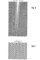
- each turn 2 as best seen in FIG. 1, has a head part 3 designed as a reversing loop and a foot part 4 designed as an opposite reversing loop.
- the respective foot part 4 has a first leg section on the one hand 5 straight or substantially straight into a corresponding first leg section 5 'of the respective subsequent turn 2.
- the head part 3 and foot part 4 each have second straight or essentially straight second leg sections 6 and 6 '.
- the second leg sections 6, 6 ' When projected onto the plane of the link belt, the second leg sections 6, 6 'run substantially congruently with the same projection of the first leg sections 5' or 5 and perpendicularly or essentially perpendicularly to the helix axis A.
- the second leg sections 6, 6 ' also go over a central win running in or essentially in the direction of the helix axis section 7 into each other.
- the individual turns 2 at their reversing loops which form the respective head part 3 or foot part 4, can be somewhat thickened compared to the other wire thickness, so that an easy engagement of adjacent wire coils 1 or 1 'into one another takes place, after which the corresponding plug wire can then be inserted through the channel formed by the reversing loops.
- the central winding section 7 is dimensioned according to its axial length so that these somewhat thickened reversing loops find space in the division-related space between the adjacent wire helices 1, 1 'without the wire helix 1, 1' being subjected to a longitudinal tension.
- the front side of the wire helixes 1, 1 ' seen in the direction of the helix axis, having a substantially flat, elongated cross section, that is to say the side of the wire helices which have the central winding sections 7, one and the same side of the Link belt facing, a link belt is also possible, in which adjacent wire coils 1, 1 ', for example, alternately have the central winding section 7 on the front and on the back of the link belt.
Landscapes
- Engineering & Computer Science (AREA)
- Mechanical Engineering (AREA)
- Textile Engineering (AREA)
- Wire Processing (AREA)
- Nonwoven Fabrics (AREA)
- Decoration Of Textiles (AREA)
- Paper (AREA)
- Filtering Materials (AREA)
- Yarns And Mechanical Finishing Of Yarns Or Ropes (AREA)
Applications Claiming Priority (2)
| Application Number | Priority Date | Filing Date | Title |
|---|---|---|---|
| DE3047989 | 1980-02-19 | ||
| DE3047989A DE3047989C2 (de) | 1980-12-19 | 1980-12-19 | Drahtwendel für die Herstellung eines flächigen Gliederbandes |
Publications (2)
| Publication Number | Publication Date |
|---|---|
| EP0054745A1 true EP0054745A1 (fr) | 1982-06-30 |
| EP0054745B1 EP0054745B1 (fr) | 1986-02-05 |
Family
ID=6119666
Family Applications (1)
| Application Number | Title | Priority Date | Filing Date |
|---|---|---|---|
| EP81109645A Expired EP0054745B1 (fr) | 1980-12-19 | 1981-11-12 | Bande articulée plane |
Country Status (4)
| Country | Link |
|---|---|
| US (1) | US4520065A (fr) |
| EP (1) | EP0054745B1 (fr) |
| JP (1) | JPS57128250A (fr) |
| DE (1) | DE3047989C2 (fr) |
Cited By (1)
| Publication number | Priority date | Publication date | Assignee | Title |
|---|---|---|---|---|
| EP0915036A1 (fr) * | 1997-11-04 | 1999-05-12 | COSTACURTA S.p.A. VICO | Bande transporteuse utilisée pour charges lourdes et/ou hautes températures |
Families Citing this family (7)
| Publication number | Priority date | Publication date | Assignee | Title |
|---|---|---|---|---|
| US4746546A (en) * | 1985-03-26 | 1988-05-24 | Asten Group, Inc. | Method of forming endless wire belt for paper machines or the like |
| DE3581930D1 (de) * | 1985-03-26 | 1991-04-04 | Asten Group | Endloses siebband fuer papiermaschinen o.dgl. |
| DE3511166A1 (de) * | 1985-03-27 | 1986-10-09 | Siteg Siebtechnik GmbH, 4422 Ahaus | Spiralgliederband mit verminderter luftdurchlaessigkeit und verfahren zu dessen herstellung |
| DE4039399A1 (de) * | 1990-12-10 | 1992-06-11 | Siteg Siebtech Gmbh | Doppelspirale, deren herstellung und deren verwendung zur herstellung eines spiralgliederbandes |
| DE4403501A1 (de) * | 1994-02-04 | 1995-08-10 | Siteg Siebtech Gmbh | Spiralgliederband niedriger Luftdurchlässigkeit und Verfahren zu seiner Herstellung |
| US7137327B2 (en) | 2002-10-31 | 2006-11-21 | Black & Decker Inc. | Riving knife assembly for a dual bevel table saw |
| CA2620889C (fr) * | 2005-08-31 | 2014-04-01 | Albany International Corp. | Tissu a liaison spiralee de flexibilite amelioree |
Citations (4)
| Publication number | Priority date | Publication date | Assignee | Title |
|---|---|---|---|---|
| DD8783A (fr) * | ||||
| DE2212776A1 (de) * | 1972-03-16 | 1973-09-20 | Christian Renz Fa | Bindespirale zur spiralbindung von losen, perforierten blaettern |
| DE2419751B2 (de) * | 1974-04-24 | 1978-08-24 | Kerber Geb. Poth, Hella, 6731 Weidenthal | Drahtgliederband z.B. für Papiermaschinen |
| EP0017722A1 (fr) * | 1979-04-23 | 1980-10-29 | SITEG Siebtechnik GmbH | Bande de tamisage faite d'hélices en matière synthétique thermodurcissable, et son procédé de fabrication |
Family Cites Families (3)
| Publication number | Priority date | Publication date | Assignee | Title |
|---|---|---|---|---|
| US851288A (en) * | 1904-12-29 | 1907-04-23 | Cyril A Smith | Ornamental chain. |
| DE738860C (de) * | 1938-05-12 | 1943-09-03 | Norddeutsche Kabelwerke Ag | Vorrichtung an einer Maschine zum Herstellen von Wendeln aus Draht oder Band |
| DE2921491A1 (de) * | 1979-05-26 | 1980-12-04 | T T Haaksbergen B V I O | Verfahren zur herstellung eines gliederbandes |
-
1980
- 1980-12-19 DE DE3047989A patent/DE3047989C2/de not_active Expired
-
1981
- 1981-11-12 EP EP81109645A patent/EP0054745B1/fr not_active Expired
- 1981-12-16 JP JP56201738A patent/JPS57128250A/ja active Pending
-
1984
- 1984-07-11 US US06/629,988 patent/US4520065A/en not_active Expired - Fee Related
Patent Citations (4)
| Publication number | Priority date | Publication date | Assignee | Title |
|---|---|---|---|---|
| DD8783A (fr) * | ||||
| DE2212776A1 (de) * | 1972-03-16 | 1973-09-20 | Christian Renz Fa | Bindespirale zur spiralbindung von losen, perforierten blaettern |
| DE2419751B2 (de) * | 1974-04-24 | 1978-08-24 | Kerber Geb. Poth, Hella, 6731 Weidenthal | Drahtgliederband z.B. für Papiermaschinen |
| EP0017722A1 (fr) * | 1979-04-23 | 1980-10-29 | SITEG Siebtechnik GmbH | Bande de tamisage faite d'hélices en matière synthétique thermodurcissable, et son procédé de fabrication |
Cited By (1)
| Publication number | Priority date | Publication date | Assignee | Title |
|---|---|---|---|---|
| EP0915036A1 (fr) * | 1997-11-04 | 1999-05-12 | COSTACURTA S.p.A. VICO | Bande transporteuse utilisée pour charges lourdes et/ou hautes températures |
Also Published As
| Publication number | Publication date |
|---|---|
| DE3047989C2 (de) | 1984-11-15 |
| EP0054745B1 (fr) | 1986-02-05 |
| JPS57128250A (en) | 1982-08-09 |
| DE3047989A1 (de) | 1982-07-15 |
| US4520065A (en) | 1985-05-28 |
Similar Documents
| Publication | Publication Date | Title |
|---|---|---|
| DE3607613C2 (de) | Spiralsaumkonstruktion | |
| EP0017722B1 (fr) | Bande de tamisage faite d'hélices en matière synthétique thermodurcissable, et son procédé de fabrication | |
| DE69710109T2 (de) | Gewickelte,gewellte Feder und deren Herstellungsweise | |
| DE69407365T2 (de) | Naht mit hoher schlingendichte | |
| CH648878A5 (de) | Verfahren zur herstellung eines gliederbandes und dadurch hergestelltes gliederband. | |
| EP0666366B1 (fr) | Tissu à hélices ayant une faible perméabilité et son procédé de fabrication | |
| DE69614891T2 (de) | Naht mit doppelten verbindungsösen und verfahren | |
| EP0116894B1 (fr) | Procédé de fabrication d'une bande de tamisage fabriquée avec spirales | |
| EP0524478B1 (fr) | Tissu en hélices combinées | |
| EP0472072B1 (fr) | Bande à maillons de fil | |
| EP0054745A1 (fr) | Bande articulée plane | |
| EP0038461B1 (fr) | Couroie de transport en treillis de fil métallique et procédé pour la fabrication de cette courroie | |
| EP0112432B1 (fr) | Bande, notamment une bande de tamisage respectivement une bande à chaînons, pour machines à papier et similaires | |
| EP0048912B1 (fr) | Support d'enroulement pour recevoir des fils | |
| DE19534486C1 (de) | Gliederband insbesondere für Papiermaschinen | |
| EP0490334B1 (fr) | Double spirale, sa fabrication et son utilisation pour la production d'une bande d'éléments spiraux | |
| DE1152072B (de) | Reissverschluss | |
| DE60017497T2 (de) | Gewebtes Reissverschlussband | |
| DE2543579C3 (de) | Streckwerks-Walzenbezug | |
| DE3344489C2 (de) | Gurtratsche | |
| DE8033835U1 (de) | "flaechiges gliederband aus drahtwendeln sowie drahtwendel fuer die herstellung eines solchen gliederbandes | |
| DE2059021A1 (de) | Vorrichtung zur Verbindung von Foerdergurten od.dgl. | |
| DE2338263C2 (de) | Vorrichtung für das Aneinanderfügen von Riemen oder Bändern | |
| DE968709C (de) | Reissverschluss aus Schraubenfedern | |
| WO2008087067A1 (fr) | Bobine électrique comprenant plusieurs couches de spires |
Legal Events
| Date | Code | Title | Description |
|---|---|---|---|
| PUAI | Public reference made under article 153(3) epc to a published international application that has entered the european phase |
Free format text: ORIGINAL CODE: 0009012 |
|
| AK | Designated contracting states |
Designated state(s): BE CH FR GB IT NL SE |
|
| 17P | Request for examination filed |
Effective date: 19821111 |
|
| GRAA | (expected) grant |
Free format text: ORIGINAL CODE: 0009210 |
|
| AK | Designated contracting states |
Designated state(s): BE CH FR GB IT LI NL SE |
|
| PG25 | Lapsed in a contracting state [announced via postgrant information from national office to epo] |
Ref country code: IT Free format text: LAPSE BECAUSE OF FAILURE TO SUBMIT A TRANSLATION OF THE DESCRIPTION OR TO PAY THE FEE WITHIN THE PRESCRIBED TIME-LIMIT;WARNING: LAPSES OF ITALIAN PATENTS WITH EFFECTIVE DATE BEFORE 2007 MAY HAVE OCCURRED AT ANY TIME BEFORE 2007. THE CORRECT EFFECTIVE DATE MAY BE DIFFERENT FROM THE ONE RECORDED. Effective date: 19860205 |
|
| ET | Fr: translation filed | ||
| PLBE | No opposition filed within time limit |
Free format text: ORIGINAL CODE: 0009261 |
|
| STAA | Information on the status of an ep patent application or granted ep patent |
Free format text: STATUS: NO OPPOSITION FILED WITHIN TIME LIMIT |
|
| 26N | No opposition filed | ||
| PGFP | Annual fee paid to national office [announced via postgrant information from national office to epo] |
Ref country code: NL Payment date: 19871130 Year of fee payment: 7 |
|
| PGFP | Annual fee paid to national office [announced via postgrant information from national office to epo] |
Ref country code: BE Payment date: 19890109 Year of fee payment: 8 |
|
| PG25 | Lapsed in a contracting state [announced via postgrant information from national office to epo] |
Ref country code: GB Effective date: 19891112 |
|
| PG25 | Lapsed in a contracting state [announced via postgrant information from national office to epo] |
Ref country code: SE Effective date: 19891113 |
|
| PG25 | Lapsed in a contracting state [announced via postgrant information from national office to epo] |
Ref country code: LI Effective date: 19891130 Ref country code: CH Effective date: 19891130 Ref country code: BE Effective date: 19891130 |
|
| BERE | Be: lapsed |
Owner name: REINHARD WERNER Effective date: 19891130 |
|
| PG25 | Lapsed in a contracting state [announced via postgrant information from national office to epo] |
Ref country code: NL Effective date: 19900601 |
|
| GBPC | Gb: european patent ceased through non-payment of renewal fee | ||
| NLV4 | Nl: lapsed or anulled due to non-payment of the annual fee | ||
| PG25 | Lapsed in a contracting state [announced via postgrant information from national office to epo] |
Ref country code: FR Effective date: 19900731 |
|
| REG | Reference to a national code |
Ref country code: CH Ref legal event code: PL |
|
| REG | Reference to a national code |
Ref country code: FR Ref legal event code: ST |
|
| EUG | Se: european patent has lapsed |
Ref document number: 81109645.2 Effective date: 19900705 |