EP0054844A1 - Dispositif hydraulique pour le lancement de navettes - Google Patents
Dispositif hydraulique pour le lancement de navettes Download PDFInfo
- Publication number
- EP0054844A1 EP0054844A1 EP81110296A EP81110296A EP0054844A1 EP 0054844 A1 EP0054844 A1 EP 0054844A1 EP 81110296 A EP81110296 A EP 81110296A EP 81110296 A EP81110296 A EP 81110296A EP 0054844 A1 EP0054844 A1 EP 0054844A1
- Authority
- EP
- European Patent Office
- Prior art keywords
- piston rod
- hydraulic
- cylinder
- valves
- control valve
- Prior art date
- Legal status (The legal status is an assumption and is not a legal conclusion. Google has not performed a legal analysis and makes no representation as to the accuracy of the status listed.)
- Granted
Links
- 238000009941 weaving Methods 0.000 abstract description 4
- 230000002146 bilateral effect Effects 0.000 description 1
- 238000013016 damping Methods 0.000 description 1
- 210000000056 organ Anatomy 0.000 description 1
- 230000008520 organization Effects 0.000 description 1
- 230000035515 penetration Effects 0.000 description 1
- 238000009527 percussion Methods 0.000 description 1
Images
Classifications
-
- D—TEXTILES; PAPER
- D03—WEAVING
- D03D—WOVEN FABRICS; METHODS OF WEAVING; LOOMS
- D03D49/00—Details or constructional features not specially adapted for looms of a particular type
- D03D49/24—Mechanisms for inserting shuttle in shed
- D03D49/42—Mechanisms for inserting shuttle in shed whereby the shuttle is propelled by liquid or gas pressure
Definitions
- the invention relates to a hydraulically operated drive means for shuttle with one disposed on each side of the sley hydraulic cylinder, in this slidable on g-e associated piston and a cylinder connected to the hydraulic control block.
- the invention has for its object to provide a fully hydraulic drive and return device.
- a hydraulically operated drive device for shooters as described in the claims in which the return of the piston rod in the actual hydraulic cylinder by the shooter - at least over part of the path length the same - is done itself, and it was surprisingly found that the dynamic pressure in the lines themselves is sufficient to bring about the required damping of the shooter and thus slow down the shooter.
- the impingement of the shooter is provided to arrive in the shuttle box in a conventional manner with a corresponding wear-resistant material, said connecting part between the contactors and the shooter blow b e - din g organization is called a picker.
- drop box systems multiple shooters are arranged above one another in a drop box and be placed according to the desired weave pattern and arranged in the protecting of thread before the shed, namely the fact that the one above the other in the drop box of g e-arranged protecting controlled accordingly lowered to the working position or be raised.
- the problem here is that when the shooter strikes the picker, for example, it is either provided from the outset or, through use, a conical recess opening into the picker is provided, into which the shooter tip enters. If the shooters are now to perform a vertical movement, this depth of penetration of the shooter in the picker prevents this upward and downward movement of the shooters and it must therefore be ensured that the striking organ, for example the picker then coming into contact with the shooter, by one further path is back, which ensures that the rifle tip is released.
- the device according to the main claim is supplemented by a third pressure medium line provided with a speed control valve, which connects to the rodless side of the hydraulic cylinder.
- the retracted shuttle shooter pushes the piston rod in the so-called acceptance position or the associated auxiliary tool back into the cylinder and the oil displaced by the piston in the hydraulic cylinder flows back via a line connection, which has been found to that the dynamic pressure in the lines is sufficient to brake and dampen the shooter sufficiently without having to open the valve connection to the tank.
- the piston rod or the associated auxiliary means reaches the so-called "end of the brake position".
- the piston rod is retracted further into the hydraulic cylinder, i.e. from the "extended piston rod end position" to an “inner end position”.
- the rifle bar is independently moved back a short way by the shooter, so that the shooter tip is not obstructed by the pick opening or what other weaving aids are available here, so that the up and down movement of the shooters in the riser is easy can.
- 1 designates a hydraulic clutch which contains a piston rod 2.
- the rodless side of the hydrauLikzyLinder 1 is denoted by A
- the side of the hydrauLik cylinder having the piston rod 2 is denoted by B.
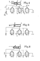
- Connected to this hydraulic cylinder 1 is a control block which has a pressure medium supply line P 1 with a speed control valve GV 1 , a control valve PA controlling the pressure medium supply line, the pressure line being designated P, a control valve TA controlling the backflow into a tank T and finally a control valve AB, which is switched between the cylinder space B and the tank.
- the speed control valve GV 1 lies in the line P 1 , to which a line 3 connects, which opens into the cylinder space B and also has a branch line 4, which is connected to the control valve AB.
- control valves AB, PA and TA are connected to one another via a connecting line VL, and a junction g VLA this Verbindun sLei- device VL is connected to the cylinder space A at the same time.
- a further pressure medium supply line P 2 opens into the line VL and a speed control valve GV 2 is switched on.
- the control valves AB, PA and TA are designed as hydraulic seat valves, for example the illustration in FIG. 1 showing that the control valve TA is closed, the control valve PA is open and the control valve AB is open.
- Fig. 1 shows the stroke position in which the control valve PA is open so that oil can flow from the pressure medium supply line P into the cylinder space A.
- the control valve AB is open, so that there is the possibility that the oil displaced from the cylinder space B can flow back to the cylinder space A via the lines 3, 4 and the connecting line VL.
- a backflow into the tank is excluded in that the control valve TA is closed.
- the so-called riser box change can now take place, i.e. the shooters in the riser can be moved up and down without any contact with the picker or the like.
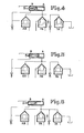
- Fig. 5 shows that there is no pressure on the lines P 1 , P and P 2 , that the control valve PA is closed, so that the piston rod by the returning shooter from position X (Fig. 4) to position Y (Fig 5) has been carried out, the piston has been pressed back into the cylinder and part of the oil flowing back can now flow back via line VL 1 , 4 and 3 into cylinder B and into tank T.
- the resulting dynamic pressure in the lines is sufficient to dampen the shooter and, as already explained above, the shooter returns the piston rod from position X to position Y, is braked and stands still in position Y (Fig. 5 ).
- control according to the invention thus enables any choice and sequence of the individual shooters in the bilateral risers.
Landscapes
- Engineering & Computer Science (AREA)
- Textile Engineering (AREA)
- Actuator (AREA)
- Looms (AREA)
Priority Applications (1)
| Application Number | Priority Date | Filing Date | Title |
|---|---|---|---|
| AT81110296T ATE7803T1 (de) | 1980-12-23 | 1981-12-10 | Hydraulisch betriebene antriebseinrichtung fuer webschuetzen. |
Applications Claiming Priority (4)
| Application Number | Priority Date | Filing Date | Title |
|---|---|---|---|
| DE3048760 | 1980-12-23 | ||
| DE3048760 | 1980-12-23 | ||
| DE3125820 | 1981-07-01 | ||
| DE19813125820 DE3125820A1 (de) | 1981-07-01 | 1981-07-01 | Hydraulisch betriebene antriebseinrichtung fuer webschuetzen |
Publications (2)
| Publication Number | Publication Date |
|---|---|
| EP0054844A1 true EP0054844A1 (fr) | 1982-06-30 |
| EP0054844B1 EP0054844B1 (fr) | 1984-06-06 |
Family
ID=25789993
Family Applications (1)
| Application Number | Title | Priority Date | Filing Date |
|---|---|---|---|
| EP81110296A Expired EP0054844B1 (fr) | 1980-12-23 | 1981-12-10 | Dispositif hydraulique pour le lancement de navettes |
Country Status (2)
| Country | Link |
|---|---|
| EP (1) | EP0054844B1 (fr) |
| DE (1) | DE3164012D1 (fr) |
Cited By (3)
| Publication number | Priority date | Publication date | Assignee | Title |
|---|---|---|---|---|
| DE3406137C1 (de) * | 1984-02-21 | 1985-08-29 | Emil Jäger GmbH & Co KG, 4400 Münster | Hydraulisch betriebene Antriebseinrichtung fuer Webschuetzen |
| DE3529288C1 (de) * | 1985-08-16 | 1986-12-18 | Emil Jäger GmbH & Co KG, 4400 Münster | Hydraulisch betriebene Antriebseinrichtung fuer Webschuetzen |
| US5027865A (en) * | 1989-06-07 | 1991-07-02 | Norlin Goeran | Controllable hydraulic picking device |
Citations (5)
| Publication number | Priority date | Publication date | Assignee | Title |
|---|---|---|---|---|
| BE551722A (fr) * | ||||
| DE806658C (de) * | 1949-01-01 | 1951-06-18 | Thomas Hindle | Schuetzentreibervorrichtung fuer Webstuehle |
| FR1333104A (fr) * | 1958-05-03 | 1963-07-26 | Procédé et dispositif pour lancer et recevoir périodiquement des objets, en particulier par des moyens hydrauliques ou pneumatiques | |
| FR1402075A (fr) * | 1964-04-29 | 1965-06-11 | Rech Etudes Prod | Dispositif hydraulique de freinage et de lancement de la navette de métier à tisser |
| FR2368562A1 (fr) * | 1976-10-20 | 1978-05-19 | Crompton & Knowles Corp | Mecanisme pneumatique de chasse pour metier a tisser |
-
1981
- 1981-12-10 EP EP81110296A patent/EP0054844B1/fr not_active Expired
- 1981-12-10 DE DE8181110296T patent/DE3164012D1/de not_active Expired
Patent Citations (5)
| Publication number | Priority date | Publication date | Assignee | Title |
|---|---|---|---|---|
| BE551722A (fr) * | ||||
| DE806658C (de) * | 1949-01-01 | 1951-06-18 | Thomas Hindle | Schuetzentreibervorrichtung fuer Webstuehle |
| FR1333104A (fr) * | 1958-05-03 | 1963-07-26 | Procédé et dispositif pour lancer et recevoir périodiquement des objets, en particulier par des moyens hydrauliques ou pneumatiques | |
| FR1402075A (fr) * | 1964-04-29 | 1965-06-11 | Rech Etudes Prod | Dispositif hydraulique de freinage et de lancement de la navette de métier à tisser |
| FR2368562A1 (fr) * | 1976-10-20 | 1978-05-19 | Crompton & Knowles Corp | Mecanisme pneumatique de chasse pour metier a tisser |
Cited By (5)
| Publication number | Priority date | Publication date | Assignee | Title |
|---|---|---|---|---|
| DE3406137C1 (de) * | 1984-02-21 | 1985-08-29 | Emil Jäger GmbH & Co KG, 4400 Münster | Hydraulisch betriebene Antriebseinrichtung fuer Webschuetzen |
| EP0152937A3 (en) * | 1984-02-21 | 1985-09-25 | Emil Jager Gmbh & Co. Kg | Hydraulic drive element for weaving shuttles |
| DE3529288C1 (de) * | 1985-08-16 | 1986-12-18 | Emil Jäger GmbH & Co KG, 4400 Münster | Hydraulisch betriebene Antriebseinrichtung fuer Webschuetzen |
| EP0215195A1 (fr) * | 1985-08-16 | 1987-03-25 | Emil Jäger GmbH & Co. KG | Dispositif de propulsion hydraulique pour navette |
| US5027865A (en) * | 1989-06-07 | 1991-07-02 | Norlin Goeran | Controllable hydraulic picking device |
Also Published As
| Publication number | Publication date |
|---|---|
| DE3164012D1 (en) | 1984-07-12 |
| EP0054844B1 (fr) | 1984-06-06 |
Similar Documents
| Publication | Publication Date | Title |
|---|---|---|
| EP1040288B1 (fr) | Unite de changement de vitesses | |
| EP0054844B1 (fr) | Dispositif hydraulique pour le lancement de navettes | |
| DE3523219C1 (de) | Hydraulischer Bagger | |
| DE2650802A1 (de) | Gas-oel-antrieb fuer vor- und ruecklaeufige mechanische verstellbewegungen | |
| DE3125820A1 (de) | Hydraulisch betriebene antriebseinrichtung fuer webschuetzen | |
| EP0152937B1 (fr) | Elément de commande hydraulique pour navettes de tissage | |
| DE1109006B (de) | Einrichtung zum Bewegen der Werkzeuge oder sonstiger beweglicher Teile an automatischen Drehmaschinen | |
| EP0373522A2 (fr) | Cylindre de commande d'outil avec soupape de réglage | |
| DE3101417A1 (de) | "hydraulisch betriebene antriebseinrichtung fuer webschuetzen" | |
| DE2918435A1 (de) | Verfahren und vorrichtung zur steuerung einer vorschubvorrichtung an einer maschine fuer sich wiederholende arbeitsvorgaenge | |
| DE2857176C1 (de) | Hydraulischer Antrieb fuer den Schuetzen einer Webmaschine | |
| DE672068C (de) | Druckluftantrieb fuer elektrische Schalter | |
| EP0215195B1 (fr) | Dispositif de propulsion hydraulique pour navette | |
| DE2339849A1 (de) | Einrichtung zur steuerung des vorund ruecklaufes einer bohrspindel | |
| DE102008004803B4 (de) | Kolben-Zylinder-Anordnung | |
| DE3709859C2 (fr) | ||
| DE2914933A1 (de) | Steuereinrichtung fuer gesenkschmiedehaemmer, insbesondere gegenschlaghaemmer | |
| AT241987B (de) | Druckmittelsteuerung für Pressen mit einer Kupplung und einer Bremse | |
| DE3211115C2 (de) | Flachsilo-Entnahmegerät | |
| DE838280C (de) | Verfahren und Vorrichtung zur periodischen und selbsttaetigen Drehung einer Welle um vorbestimmte Winkel, die von einer Lochkarte gesteuert werden, insbesondere zur wahlweisen Einschaltung verschiedener Garnschuetzen auf Webmaschinen | |
| DE1535279C (de) | Webmaschine | |
| DE1064005B (de) | Stosstraenkgeraet mit einem durch Druckluft betriebenen Differentialkolben | |
| DE2235618B2 (de) | Automatische Steuerung der Druckmittelzufuhr zu einem Schlagbohrhammer | |
| DE1134052B (de) | Vorschubantrieb fuer eine Werkstueckzufuehreinrichtung an Gewinderollmaschinen | |
| DE1245293B (de) | Hydraulischer Rueckzylinder zum Ruecken von entlang dem Kohlenstoss angeordneten Ausbaueinheiten |
Legal Events
| Date | Code | Title | Description |
|---|---|---|---|
| PUAI | Public reference made under article 153(3) epc to a published international application that has entered the european phase |
Free format text: ORIGINAL CODE: 0009012 |
|
| AK | Designated contracting states |
Designated state(s): AT BE CH DE FR GB IT NL SE |
|
| 17P | Request for examination filed |
Effective date: 19820610 |
|
| ITF | It: translation for a ep patent filed | ||
| GRAA | (expected) grant |
Free format text: ORIGINAL CODE: 0009210 |
|
| AK | Designated contracting states |
Designated state(s): AT BE CH DE FR GB IT LI NL SE |
|
| REF | Corresponds to: |
Ref document number: 7803 Country of ref document: AT Date of ref document: 19840615 Kind code of ref document: T |
|
| REF | Corresponds to: |
Ref document number: 3164012 Country of ref document: DE Date of ref document: 19840712 |
|
| ET | Fr: translation filed | ||
| PGFP | Annual fee paid to national office [announced via postgrant information from national office to epo] |
Ref country code: SE Payment date: 19840930 Year of fee payment: 4 |
|
| PGFP | Annual fee paid to national office [announced via postgrant information from national office to epo] |
Ref country code: FR Payment date: 19841109 Year of fee payment: 4 |
|
| PGFP | Annual fee paid to national office [announced via postgrant information from national office to epo] |
Ref country code: DE Payment date: 19841219 Year of fee payment: 4 |
|
| PGFP | Annual fee paid to national office [announced via postgrant information from national office to epo] |
Ref country code: BE Payment date: 19841231 Year of fee payment: 4 |
|
| PLBE | No opposition filed within time limit |
Free format text: ORIGINAL CODE: 0009261 |
|
| STAA | Information on the status of an ep patent application or granted ep patent |
Free format text: STATUS: NO OPPOSITION FILED WITHIN TIME LIMIT |
|
| 26N | No opposition filed | ||
| PGFP | Annual fee paid to national office [announced via postgrant information from national office to epo] |
Ref country code: AT Payment date: 19861030 Year of fee payment: 6 |
|
| PGFP | Annual fee paid to national office [announced via postgrant information from national office to epo] |
Ref country code: NL Payment date: 19871231 Year of fee payment: 7 |
|
| PG25 | Lapsed in a contracting state [announced via postgrant information from national office to epo] |
Ref country code: GB Effective date: 19881210 Ref country code: AT Effective date: 19881210 |
|
| PG25 | Lapsed in a contracting state [announced via postgrant information from national office to epo] |
Ref country code: SE Effective date: 19881211 |
|
| PG25 | Lapsed in a contracting state [announced via postgrant information from national office to epo] |
Ref country code: LI Effective date: 19881231 Ref country code: CH Effective date: 19881231 Ref country code: BE Effective date: 19881231 |
|
| BERE | Be: lapsed |
Owner name: EMIL JAGER K.G. Effective date: 19881231 |
|
| PG25 | Lapsed in a contracting state [announced via postgrant information from national office to epo] |
Ref country code: NL Effective date: 19890701 |
|
| NLV4 | Nl: lapsed or anulled due to non-payment of the annual fee | ||
| GBPC | Gb: european patent ceased through non-payment of renewal fee | ||
| PG25 | Lapsed in a contracting state [announced via postgrant information from national office to epo] |
Ref country code: FR Free format text: LAPSE BECAUSE OF NON-PAYMENT OF DUE FEES Effective date: 19890831 |
|
| REG | Reference to a national code |
Ref country code: CH Ref legal event code: PL |
|
| PG25 | Lapsed in a contracting state [announced via postgrant information from national office to epo] |
Ref country code: DE Effective date: 19890901 |
|
| REG | Reference to a national code |
Ref country code: FR Ref legal event code: ST |
|
| EUG | Se: european patent has lapsed |
Ref document number: 81110296.1 Effective date: 19891215 |