EP0054928B1 - Combinaison d'une fixation de ski de randonnée avec un frein de ski - Google Patents
Combinaison d'une fixation de ski de randonnée avec un frein de ski Download PDFInfo
- Publication number
- EP0054928B1 EP0054928B1 EP81110571A EP81110571A EP0054928B1 EP 0054928 B1 EP0054928 B1 EP 0054928B1 EP 81110571 A EP81110571 A EP 81110571A EP 81110571 A EP81110571 A EP 81110571A EP 0054928 B1 EP0054928 B1 EP 0054928B1
- Authority
- EP
- European Patent Office
- Prior art keywords
- ski
- bearing
- combination according
- brake
- binding part
- Prior art date
- Legal status (The legal status is an assumption and is not a legal conclusion. Google has not performed a legal analysis and makes no representation as to the accuracy of the status listed.)
- Expired
Links
Images


Classifications
-
- A—HUMAN NECESSITIES
- A63—SPORTS; GAMES; AMUSEMENTS
- A63C—SKATES; SKIS; ROLLER SKATES; DESIGN OR LAYOUT OF COURTS, RINKS OR THE LIKE
- A63C7/00—Devices preventing skis from slipping back; Ski-stoppers or ski-brakes
- A63C7/10—Hinged stoppage blades attachable to the skis in such manner that these blades can be moved out of the operative position
- A63C7/1006—Ski-stoppers
- A63C7/1013—Ski-stoppers actuated by the boot
- A63C7/102—Ski-stoppers actuated by the boot articulated about one transverse axis
- A63C7/1026—Ski-stoppers actuated by the boot articulated about one transverse axis laterally retractable above the ski surface
-
- A—HUMAN NECESSITIES
- A63—SPORTS; GAMES; AMUSEMENTS
- A63C—SKATES; SKIS; ROLLER SKATES; DESIGN OR LAYOUT OF COURTS, RINKS OR THE LIKE
- A63C7/00—Devices preventing skis from slipping back; Ski-stoppers or ski-brakes
- A63C7/10—Hinged stoppage blades attachable to the skis in such manner that these blades can be moved out of the operative position
- A63C7/1006—Ski-stoppers
- A63C7/1013—Ski-stoppers actuated by the boot
- A63C7/1033—Ski-stoppers actuated by the boot articulated about at least two transverse axes
- A63C7/104—Ski-stoppers actuated by the boot articulated about at least two transverse axes laterally retractable above the ski surface
-
- A—HUMAN NECESSITIES
- A63—SPORTS; GAMES; AMUSEMENTS
- A63C—SKATES; SKIS; ROLLER SKATES; DESIGN OR LAYOUT OF COURTS, RINKS OR THE LIKE
- A63C9/00—Ski bindings
- A63C9/08—Ski bindings yieldable or self-releasing in the event of an accident, i.e. safety bindings
- A63C9/081—Ski bindings yieldable or self-releasing in the event of an accident, i.e. safety bindings with swivel sole-plate
-
- A—HUMAN NECESSITIES
- A63—SPORTS; GAMES; AMUSEMENTS
- A63C—SKATES; SKIS; ROLLER SKATES; DESIGN OR LAYOUT OF COURTS, RINKS OR THE LIKE
- A63C9/00—Ski bindings
- A63C9/08—Ski bindings yieldable or self-releasing in the event of an accident, i.e. safety bindings
- A63C9/085—Ski bindings yieldable or self-releasing in the event of an accident, i.e. safety bindings with sole hold-downs, e.g. swingable
- A63C9/08535—Ski bindings yieldable or self-releasing in the event of an accident, i.e. safety bindings with sole hold-downs, e.g. swingable with a mobile body or base or single jaw
- A63C9/08542—Ski bindings yieldable or self-releasing in the event of an accident, i.e. safety bindings with sole hold-downs, e.g. swingable with a mobile body or base or single jaw pivoting about a transversal axis
Definitions
- the invention relates to a combination of touring ski binding and ski brake.
- touring ski bindings In the case of touring ski bindings, it has previously been customary to secure the ski that is released from the boot with a safety strap. While this is appropriate for deep snow skiing, modern touring bindings, which are designed as safety ski bindings and can be attached to the ski, are also suitable for downhill skiing on slopes. In this case, the use of a lanyard is often rejected by the skier because of his own risk of accident, which is caused by the ski hanging loosely from the lanyard and connected to the ski boot.
- ski brake The previously known alternative to a lanyard, namely a ski brake, has already been used in conjunction with a touring ski binding (CH-A-598 837), but the ski brake is ineffective when using the ski binding as a touring binding, since it is only used as a return device is effective for the step frame when walking.
- the ski boot can usually only be released from the touring frame in the event of a sudden fall, since the touring frame is pivoted in the event of a frontal fall and the possibility is therefore low that the rear sole holder opens. In this case, however, the brake would be ineffective according to EP-A-0 031 570.
- a ski brake that is not subject to these restrictions is known from DE-A-28 38 902.
- the object of the invention is to provide a combination of touring ski binding and ski brake, in which the ski brake can always come into the effective braking position regardless of the position of use of the pivotable binding part when the boot is released from the pivotable binding part, without affecting the various operating modes the touring binding, whereby the ski brake is only held in its inactive position by the boot without additional parts.
- the ski brake should not hinder touring.
- ski binding is attached to the pivotable binding part and can be transferred to the braking position independently of the binding parts.
- This configuration means that the ski brake is held in its ineffective position by the boot resting on the touring frame or touring plate. As soon as the boot is released from the swiveling binding part, the ski brake comes into its effective position due to its spring force and brakes the ski or prevents it from slipping. The ski is therefore always secured regardless of whether the boot is released due to a triggering process of the safety part of the ski binding or by arbitrarily opening the binding. It does not matter whether the ski boot has been released due to a frontal fall or a fall because a connection to a release part of the ski binding is missing. Additional parts that hold the ski brake in its inactive position are no longer required.
- the ski brake is detachably arranged on the pivotable binding part in a development of the invention.
- the ski brake can be removed in a simple manner when using safety straps, so that it does not pose a risk of accident if the ski is held on the boot by the safety strap and the ski brake is in the effective position into which it is due to the loose connection of ski boots and Skis could endanger the skier through the lanyard.
- the ski brake has a bearing part that has receptacles on its outer areas that serve to hold the ski brake on the pivotable binding part and that a locking device is provided on the bearing part, which relates the bearing part to the longitudinal direction of the pivotable binding part fixes on this.
- This configuration achieves the object of arranging the ski brake on a pivotable binding part designed as a touring frame in such a way that the safety release part arranged on the touring frame and the length compensation are not impaired, i.e. that no forces are transmitted from the bearing part of the ski binding to the touring frame, which could lead to deformation thereof, since the restoring forces of the brake bracket can be absorbed by the bearing part, regardless of whether it is an elastically deformable brake bracket without an additional return spring or a Ski brake acts in which the brake bracket is pulled or pressed into its effective position by additional springs.
- the bearing part can be constructed from two bearing blocks and a connecting web connecting the bearing blocks.
- the spacer is designed according to claim 10, it is possible to keep the legs of this wire bracket in the immediate vicinity of the inside of the legs of the touring frame, so that no additional disruptive surfaces between the legs of the touring frame arise.
- the pivotable design of the spacer generally has the advantage that it can be brought into a position parallel to the brake bracket when the ski brake is removed, so that no bulky component is formed which can easily be inserted into an anorak pocket when the skier is using a Lanyard preferred.
- the bearing blocks from a plastic suitable for storage purposes and the connecting web or the supporting part from a strong sheet metal, it is possible to absorb the forces resulting from the deformation of the elastic brake bracket completely in the bearing part without the touring frame with them Forces.
- the control surfaces necessary for the deformation, which in conjunction with the elastic deformability of the bracket cause the return of the brake bracket into its effective position, are provided according to an advantageous embodiment of the invention on the mutually facing sides of the bearing blocks, so that they are simple to manufacture the pedestals can be cast on.
- the advantage is achieved that the snow building up on the ski below the bearing part is divided and pressed apart by the roof-shaped or wedge-shaped bearing part, as a result of which a greater accumulation of snow under this part is avoided when touring.
- An impairment of touring by the ski brake is thus largely avoided, which does not interfere with their arrangement between the legs and due to their low height in the ineffective position, which, according to claim 14, corresponds at most to the height of the sole receiving webs arranged on the step frame.
- the low height in the inactive position is achieved in a further embodiment of the invention according to claim 15. Since the touring frame rests in a front bearing and on a rear locking device, a small gap between the ski and the touring frame remains in the position fixed on the ski, which is sufficient to accommodate the horizontal bearing sections of the brake bracket. Since the brake bracket is held under prestress on the bearing blocks by the Q-shaped part which widens obliquely upwards, so that it cannot fall down, the bearing recesses can be open at the bottom and only so deep that the bearing sections of the brake bracket fit into it . This not only saves height, but also significantly simplifies the assembly of the brake bracket in the bearing blocks.
- the brake bracket can namely be elastically pushed apart so far that it is released by its rotation relative to the bearing blocks and can be pulled down out of the bearing part if a correspondingly large recess is provided in the bearing part carrying the bearing blocks.
- connecting plates hold the bearing blocks together, this is not possible, but these connecting plates can be detached from the bearing blocks in a simple manner by means of a screw connection.
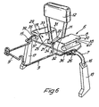
- the pivotable binding part designated as 1, which is designed as a touring frame, is shown of the touring ski binding.
- This touring frame has two legs 2 and 3 with a circular cross section, which in their front area carry a sole receiving web 4, on which a front sole holder 5 is arranged.
- the rear sole receiving web with the safety release part of the touring ski binding is not shown because this is not necessary for an understanding of the invention.
- the touring frame 1 is pivotally mounted about an axis extending transversely to the longitudinal axis of the ski in a bearing part not shown in the drawing, so that when touring the touring frame can be pivoted up about this front axis, as a result of which the boot can be lifted off the ski.
- a ski brake is arranged in the vicinity of the front sole receiving web 4.
- the ski brake comprises a 7 designated, resiliently designed brake bracket, which is pivotally mounted in a bearing part 8 and is held in relation to the longitudinal axis of the pivotable binding part 1 by a spacer 9 which is pivotably mounted on the brake bracket and which is offset by an offset 9 ' Opening 10 of the front sole receiving web is suspended and is supported there, so that the ski brake is locked at a very specific point on the touring frame.
- the brake bracket 7 which is made in one piece from a resilient wire, has an upper Q-shaped part 11 with a tread plate 12 and two horizontally running bearing sections 13 and 14, each of which is connected to a brake arm 15 and 16.
- the brake arms 15 and 16 have brake shoes 17 and 18 made of plastic, which are attached to the free ends of the brake bracket 7 and fastened there.
- the brake bracket 7 is pivotally mounted with its horizontally extending bearing sections 13 and 14 in the bearing part 8, this bearing part being constructed from two bearing blocks 19 and 20 made of plastic with self-lubricating properties and from two connecting webs 21 and 22 arranged on the underside of the bearing blocks.
- the bearing blocks 19 and 20 are provided on their underside with roof-shaped surfaces 23 and 24 on which the connecting webs 21 and 22 abut, as a result of which they are inclined to one another in such a way that the adjacent edges of the connecting webs at the thickest point of the bearing blocks lie so that a wedge effect is exerted on the snow accumulating on the ski. This prevents icing due to the snow being pressed on the ski below the ski brake.
- the bearing blocks 19 and 20 have on their underside in the middle downwardly open bearing recesses 25 and 26 which are so deep that the bearing sections 13 and 14 of the brake bracket 7 are completely accommodated. With its curved transition regions 27 and 28 between the bearing sections 13 and 14 and the adjoining loop-shaped part 11, the brake bracket 7 bears against control surfaces 29 and 30 of the bearing blocks 19 and 20 under prestress.
- the control surfaces 29 and 30 each have a detent recess 31 or 32 in the central plane of the pedestal, in which the brake bracket 7 is held in its effective or braking position.
- the bearing blocks 19 and 20 have on their side surfaces parallel to the outer ski edges receiving grooves 35 and 36, which are adapted to the shape of the legs 2 and 3 and fit essentially tension-free between them.
- the receiving grooves 35 and 36 are rounded inward, the arcuate receiving grooves 37 and 38 also being at a mutual distance which essentially corresponds to the distance between the two legs 2 and 3 of the touring frame.
- the mutual distance between these sections, designated 39 and 40 and serving as locking cams is somewhat larger than the mutual distance between the legs 2 and 3 of the pivotable binding part 1.
- the ski brake is inserted into the touring frame in such a way that the bearing part 8 is inserted in an interlocked position between the legs 2 and 3 of the touring frame, the interlocking of the bearing part with respect to the touring frame being carried out in such a way that the arcuate receiving grooves 37 and 38 pick up legs 2 and 3.
- the locking cams 39 and 40 briefly pushing apart the legs 2 and 3 of the touring frame, the legs 2 and 3 enter the receiving grooves 35 and 36, as a result of which the bearing part is in the position of use shown in FIG. 1.
- the legs 2 and 3 spring back elastically after the locking cams 39 and 40 are exceeded during the turning process.
- the bearing part is fixed by the pivotable spacer 9, in which this spacer, which is designed as a U-shaped wire bracket, is inserted with its offset 9 'into the opening 10 of the sole receiving web.
- the spacer 9 is designed so that it rests on the inside of the legs 2 and 3 on these in the use position.
- the bearing part 8 In the use position between the legs 2 and 3, the bearing part 8 is held in such a way that the horizontal bearing sections 13 and 14 rest against the legs 2 and 3 from below. Since the Q-shaped section 11 widens upwards and rests with prestress on the bearing blocks, the brake bracket cannot fall out downwards.
- Fig. 1 an arrow is drawn, which indicates the direction of rotation in which the bearing part 8 must be moved in order to bring it out of its position of use between the legs 2 and 3 again.
- the ski brake designated overall by 45 comprises a bearing part 46 on which bearing blocks 41 and 42 are arranged, which on their mutually facing sides are provided with control surfaces 43 and 44 corresponding to the control surfaces 29 and 30 in the first exemplary embodiment are used to deform the brake bracket 7 when pivoted.
- the bearing part 46 also has a support part 47, which connects the two bearing blocks 41 and 42 to one another, is designed as a shell, and has edge regions 48 and 49 which are curved upwards and inwards and extend in the longitudinal direction of the pivotable binding part designed as a touring frame, of which legs 2 and 3 of the touring frame in the use position of the ski brake 45 are partially included, in this use position the bearing blocks 41 and 42 abut the inside of the legs 2 and 3.
- the edge regions 48 and 49 are elastically bent outwards so that the legs 2 and 3 of the pivotable binding part 1, i.e. of the touring frame, into which receptacles formed by the edge areas 48 and 49 on the one hand and the outside 50 and 51 of the bearing blocks 41 and 42 on the other hand can snap in, which is not possible without this deformation because the edges 52 and 53 of the edge areas 48 and 49 are so close to the outer sides 50 and 51 of the bearing blocks 41 and 42 reach that this remaining distance is smaller than the diameter of the legs 2 and 3.
- the ski brake 45 is held on the touring frame 1, the locking on the touring frame, ie the ski brake is fixed at a specific place on the touring frame by means of a latching tongue 54 which is integrally formed on the shell 47 and which can be latched into the opening 10 of the sole receiving web 4.
- the shell 47 thus takes over the function of the connecting webs 21 and 22 for the bearing blocks 19 and 20 and the spacer 9 in the embodiment according to FIGS. 1 to 6.
- the bearing blocks 41 and 42 slidably on the shell 47 in order to prevent the edge regions 48 and 49 from bending apart if the shell 47 is made of one material which does not have the necessary elastic properties that are necessary to to be able to bend the edge regions so far apart that the legs 2 and 3 can be accommodated between the bearing blocks and the edge regions.
- the tread plate 12 can also be arranged pivotably on the Q-shaped part 11 of the brake bracket 7 in order to facilitate the pivoting of the brake bracket by the ski boot.
- the bearing blocks 41 and 42 are provided on their underside with downwardly open bearing recesses 55 and 56, in which the horizontal bearing sections 13 and 14 are completely accommodated.
- the brake bracket is also held here by the upwardly obliquely widening Q-shaped part with pretension between the bearing blocks, so that it cannot fall downward despite a recess 57 in the support part 47.
- the recess 57 in the support part 47 is necessary so that the brake bracket with its horizontally running bearing sections can be arranged below the legs 2 and 3 of the touring frame.
- support tabs 58 and 59 of the supporting part 47 are bent downward and form inclined surfaces on which the bearing blocks provided with corresponding inclined surfaces rest, as is the case with the first embodiment and can be seen particularly clearly from FIG. 3.
Landscapes
- Footwear And Its Accessory, Manufacturing Method And Apparatuses (AREA)
- Handcart (AREA)
- Aerials With Secondary Devices (AREA)
- Control Of Position Or Direction (AREA)
- Fittings On The Vehicle Exterior For Carrying Loads, And Devices For Holding Or Mounting Articles (AREA)
Claims (15)
Priority Applications (1)
| Application Number | Priority Date | Filing Date | Title |
|---|---|---|---|
| AT81110571T ATE28404T1 (de) | 1980-12-19 | 1981-12-18 | Kombination einer tourenskibindung und skibremse. |
Applications Claiming Priority (2)
| Application Number | Priority Date | Filing Date | Title |
|---|---|---|---|
| DE3048175 | 1980-12-19 | ||
| DE19803048175 DE3048175A1 (de) | 1980-12-19 | 1980-12-19 | Tourenbindung mit skistopper |
Publications (3)
| Publication Number | Publication Date |
|---|---|
| EP0054928A1 EP0054928A1 (fr) | 1982-06-30 |
| EP0054928B1 true EP0054928B1 (fr) | 1987-07-22 |
| EP0054928B2 EP0054928B2 (fr) | 1990-11-14 |
Family
ID=6119745
Family Applications (1)
| Application Number | Title | Priority Date | Filing Date |
|---|---|---|---|
| EP81110571A Expired - Lifetime EP0054928B2 (fr) | 1980-12-19 | 1981-12-18 | Combinaison d'une fixation de ski de randonnée avec un frein de ski |
Country Status (5)
| Country | Link |
|---|---|
| US (1) | US4498685A (fr) |
| EP (1) | EP0054928B2 (fr) |
| JP (1) | JPS57128177A (fr) |
| AT (1) | ATE28404T1 (fr) |
| DE (1) | DE3048175A1 (fr) |
Families Citing this family (14)
| Publication number | Priority date | Publication date | Assignee | Title |
|---|---|---|---|---|
| FR2584935B1 (fr) * | 1985-07-22 | 1988-03-11 | Pitel Serge | Dispositif-frein empechant les skis de glisser |
| AT391274B (de) * | 1988-09-01 | 1990-09-10 | Tyrolia Freizeitgeraete | Skibindung |
| US5008041A (en) * | 1990-01-30 | 1991-04-16 | Lockheed Corporation | Preparation of conductive polyaniline having controlled molecular weight |
| DE4325175A1 (de) * | 1993-07-27 | 1995-02-02 | Marker Deutschland Gmbh | Bremsarm einer Skibremse |
| AT404675B (de) * | 1996-03-20 | 1999-01-25 | Josef Peter Schnitzhofer | Sicherheitsbindung für snowbord |
| FR2749483B1 (fr) * | 1996-06-06 | 1998-09-11 | Salomon Sa | Dispositif de retenue d'une chaussure sur une planche de glisse |
| WO1999006127A1 (fr) * | 1997-08-02 | 1999-02-11 | Roger Marcel Humbel | Fixation de securite pour planche a neige |
| US7207591B2 (en) * | 2001-05-08 | 2007-04-24 | Rottefella As | Ski binding |
| DE202009019109U1 (de) * | 2008-02-29 | 2016-09-05 | G3 Genuine Guide Gear Inc. | Ferseneinheit für Tourenskibindung |
| FR2952546B1 (fr) * | 2009-11-17 | 2011-12-09 | Rossignol Sa | Dispositif de freinage de planche de glisse |
| DE102012214001B4 (de) * | 2012-08-07 | 2014-03-13 | Marker Deutschland Gmbh | Skibremse mit Verriegelung |
| FR2999090A1 (fr) * | 2012-12-10 | 2014-06-13 | Rossignol Sa | Dispositif de freinage pour ski de randonnee |
| US9242167B2 (en) | 2013-07-09 | 2016-01-26 | G3 Genuine Guide Gear Inc. | Ski binding heel unit |
| DE102019108350A1 (de) * | 2019-03-29 | 2020-10-01 | Marker Deutschland Gmbh | Bremsvorrichtung |
Family Cites Families (14)
| Publication number | Priority date | Publication date | Assignee | Title |
|---|---|---|---|---|
| AT17179B (de) * | 1903-11-18 | 1904-08-10 | Josef Muehlhauser S Nachfolger | Schneeschuh. |
| US1101631A (en) * | 1912-10-21 | 1914-06-30 | George Lander Jacques | Skee-skate. |
| US1223882A (en) * | 1915-02-04 | 1917-04-24 | George Lander Jacques | Skee-skate. |
| AT315046B (de) * | 1972-04-24 | 1974-05-10 | Vinzenz Saller | Skibindung |
| DE2523012A1 (de) * | 1975-05-23 | 1976-12-02 | Salomon & Fils F | Vorrichtung zum abbremsen des skis nach dem loesen vom skischuh (skibremse) |
| AT347837B (de) * | 1975-09-23 | 1979-01-10 | Smolka & Co Wiener Metall | Skibremse |
| AT364634B (de) * | 1976-04-16 | 1981-11-10 | Tyrolia Freizeitgeraete | Skibremse |
| AT345136B (de) * | 1976-09-24 | 1978-08-25 | Smolka & Co Wiener Metall | Verbindungselement |
| CH598837A5 (en) * | 1976-10-22 | 1978-05-12 | Hans Naepflin | Multi-purpose ski brake |
| DE2756525A1 (de) * | 1977-12-19 | 1979-06-21 | Ver Baubeschlag Gretsch Co | An der grundplatte einer skibindung loesbar angeordnete skibremse |
| US4231584A (en) * | 1977-12-21 | 1980-11-04 | Hope Co., Ltd. | Ski boot heel binding equipped with ski brake |
| FR2412325A1 (fr) * | 1977-12-23 | 1979-07-20 | Mitchell Sa | Fixation de securite pour ski |
| DE2828056A1 (de) * | 1978-06-26 | 1980-01-10 | Karl Schuller | Skibremse |
| DE2838902A1 (de) * | 1978-09-06 | 1980-03-20 | Peter Ortmaier | Vorrichtung zur loesbaren halterung eines skischuhes an einem ski |
-
1980
- 1980-12-19 DE DE19803048175 patent/DE3048175A1/de active Granted
-
1981
- 1981-12-17 US US06/331,928 patent/US4498685A/en not_active Expired - Fee Related
- 1981-12-18 EP EP81110571A patent/EP0054928B2/fr not_active Expired - Lifetime
- 1981-12-18 AT AT81110571T patent/ATE28404T1/de not_active IP Right Cessation
- 1981-12-19 JP JP56204547A patent/JPS57128177A/ja active Pending
Also Published As
| Publication number | Publication date |
|---|---|
| US4498685A (en) | 1985-02-12 |
| DE3048175A1 (de) | 1982-07-22 |
| DE3048175C2 (fr) | 1989-06-08 |
| JPS57128177A (en) | 1982-08-09 |
| EP0054928A1 (fr) | 1982-06-30 |
| EP0054928B2 (fr) | 1990-11-14 |
| ATE28404T1 (de) | 1987-08-15 |
Similar Documents
| Publication | Publication Date | Title |
|---|---|---|
| EP0054928B1 (fr) | Combinaison d'une fixation de ski de randonnée avec un frein de ski | |
| DE2756897A1 (de) | Sicherheitsskibindung | |
| EP0152629B1 (fr) | Fixation de ski | |
| DE102013204065B4 (de) | Hinterbacken mit einer Skibremse für eine Skitourenbindung | |
| EP0446780A2 (fr) | Fixation de la butée avant | |
| DE7104814U (de) | Auslösevorrichtung für eine am Ski befestigbare Bremsvorrichtung | |
| DE2836481A1 (de) | Sicherheitsbindung fuer ski | |
| EP0269664B1 (fr) | Frein de ski | |
| DE3143576C2 (de) | Backen, insbesondere Vorderbacken, für Sicherheitsskibindungen | |
| DE2235180A1 (de) | Skibindung in zehenbindungsbauart | |
| DE2527617B2 (de) | Kombination aus Sicherheits-Skibindung und Skischuh | |
| DE102016000609B4 (de) | Hinterbackenvorrichtung für eine Tourenskibindung | |
| DE69202327T2 (de) | Zwischenliegendes Stück für die Führungsschiene eines Bindungseinzelteils, insbesondere einer Skibindung. | |
| EP0176952A1 (fr) | Combinaison d'une fixation de ski et d'une chaussure | |
| DE7039190U (de) | Skibremse | |
| AT406339B (de) | Snowboardbindung | |
| DE10319675A1 (de) | Skibindung, insbesondere Touren-, Telemark- oder Langlaufbindung | |
| EP0272317B1 (fr) | Fixation de securite pour ski | |
| WO2023118549A1 (fr) | Système de fixation pour une fixation de ski de randonnée | |
| EP0113415B1 (fr) | Fixation de sécurité pour ski de fond | |
| EP0665035B1 (fr) | Dispositif de fixation sur un ski | |
| AT359897B (de) | Ausloeseskibindung | |
| EP0474827A1 (fr) | Fixation pour ski de fond ou de randonnee. | |
| AT378126B (de) | Rueckgleitsperre fuer langlaufschi | |
| EP0536550A1 (fr) | Dispositif mordant dans la neige |
Legal Events
| Date | Code | Title | Description |
|---|---|---|---|
| PUAI | Public reference made under article 153(3) epc to a published international application that has entered the european phase |
Free format text: ORIGINAL CODE: 0009012 |
|
| 17P | Request for examination filed |
Effective date: 19820317 |
|
| AK | Designated contracting states |
Designated state(s): AT CH FR IT |
|
| GRAA | (expected) grant |
Free format text: ORIGINAL CODE: 0009210 |
|
| AK | Designated contracting states |
Kind code of ref document: B1 Designated state(s): AT CH FR IT LI |
|
| REF | Corresponds to: |
Ref document number: 28404 Country of ref document: AT Date of ref document: 19870815 Kind code of ref document: T |
|
| ET | Fr: translation filed | ||
| ITF | It: translation for a ep patent filed | ||
| PLBI | Opposition filed |
Free format text: ORIGINAL CODE: 0009260 |
|
| 26 | Opposition filed |
Opponent name: TYROLIA FREIZEITGERAETE GESELLSCHAFT M.B.H. & CO. Effective date: 19880422 |
|
| PUAH | Patent maintained in amended form |
Free format text: ORIGINAL CODE: 0009272 |
|
| STAA | Information on the status of an ep patent application or granted ep patent |
Free format text: STATUS: PATENT MAINTAINED AS AMENDED |
|
| 27A | Patent maintained in amended form |
Effective date: 19901114 |
|
| AK | Designated contracting states |
Kind code of ref document: B2 Designated state(s): AT CH FR IT LI |
|
| ET3 | Fr: translation filed ** decision concerning opposition | ||
| ITTA | It: last paid annual fee | ||
| ITF | It: translation for a ep patent filed | ||
| PGFP | Annual fee paid to national office [announced via postgrant information from national office to epo] |
Ref country code: FR Payment date: 19951122 Year of fee payment: 15 |
|
| PGFP | Annual fee paid to national office [announced via postgrant information from national office to epo] |
Ref country code: CH Payment date: 19951201 Year of fee payment: 15 |
|
| PGFP | Annual fee paid to national office [announced via postgrant information from national office to epo] |
Ref country code: AT Payment date: 19951231 Year of fee payment: 15 |
|
| PG25 | Lapsed in a contracting state [announced via postgrant information from national office to epo] |
Ref country code: AT Effective date: 19961218 |
|
| PG25 | Lapsed in a contracting state [announced via postgrant information from national office to epo] |
Ref country code: LI Effective date: 19961231 Ref country code: CH Effective date: 19961231 |
|
| REG | Reference to a national code |
Ref country code: CH Ref legal event code: PL |
|
| PG25 | Lapsed in a contracting state [announced via postgrant information from national office to epo] |
Ref country code: FR Effective date: 19970829 |
|
| REG | Reference to a national code |
Ref country code: FR Ref legal event code: ST |