EP0054978A1 - Dispositif de sciage - Google Patents
Dispositif de sciage Download PDFInfo
- Publication number
- EP0054978A1 EP0054978A1 EP81110785A EP81110785A EP0054978A1 EP 0054978 A1 EP0054978 A1 EP 0054978A1 EP 81110785 A EP81110785 A EP 81110785A EP 81110785 A EP81110785 A EP 81110785A EP 0054978 A1 EP0054978 A1 EP 0054978A1
- Authority
- EP
- European Patent Office
- Prior art keywords
- saw unit
- movement
- work table
- lifting
- saw
- Prior art date
- Legal status (The legal status is an assumption and is not a legal conclusion. Google has not performed a legal analysis and makes no representation as to the accuracy of the status listed.)
- Granted
Links
- 230000005540 biological transmission Effects 0.000 claims description 9
- 230000007246 mechanism Effects 0.000 claims description 5
- 230000001419 dependent effect Effects 0.000 claims description 4
- 230000005484 gravity Effects 0.000 claims description 3
- 230000000452 restraining effect Effects 0.000 claims 1
- 238000010276 construction Methods 0.000 description 6
- 238000005520 cutting process Methods 0.000 description 4
- 238000006073 displacement reaction Methods 0.000 description 3
- 230000008901 benefit Effects 0.000 description 2
- 238000004519 manufacturing process Methods 0.000 description 2
- 238000000034 method Methods 0.000 description 2
- 230000008569 process Effects 0.000 description 2
- 238000004804 winding Methods 0.000 description 2
- 230000008859 change Effects 0.000 description 1
- 230000002349 favourable effect Effects 0.000 description 1
- 238000009434 installation Methods 0.000 description 1
- 238000003754 machining Methods 0.000 description 1
- 230000014759 maintenance of location Effects 0.000 description 1
- 230000008092 positive effect Effects 0.000 description 1
- 230000002441 reversible effect Effects 0.000 description 1
- 238000009331 sowing Methods 0.000 description 1
Images


Classifications
-
- B—PERFORMING OPERATIONS; TRANSPORTING
- B23—MACHINE TOOLS; METAL-WORKING NOT OTHERWISE PROVIDED FOR
- B23D—PLANING; SLOTTING; SHEARING; BROACHING; SAWING; FILING; SCRAPING; LIKE OPERATIONS FOR WORKING METAL BY REMOVING MATERIAL, NOT OTHERWISE PROVIDED FOR
- B23D47/00—Sawing machines or sawing devices working with circular saw blades, characterised only by constructional features of particular parts
- B23D47/02—Sawing machines or sawing devices working with circular saw blades, characterised only by constructional features of particular parts of frames; of guiding arrangements for work-table or saw-carrier
-
- B—PERFORMING OPERATIONS; TRANSPORTING
- B23—MACHINE TOOLS; METAL-WORKING NOT OTHERWISE PROVIDED FOR
- B23Q—DETAILS, COMPONENTS, OR ACCESSORIES FOR MACHINE TOOLS, e.g. ARRANGEMENTS FOR COPYING OR CONTROLLING; MACHINE TOOLS IN GENERAL CHARACTERISED BY THE CONSTRUCTION OF PARTICULAR DETAILS OR COMPONENTS; COMBINATIONS OR ASSOCIATIONS OF METAL-WORKING MACHINES, NOT DIRECTED TO A PARTICULAR RESULT
- B23Q1/00—Members which are comprised in the general build-up of a form of machine, particularly relatively large fixed members
- B23Q1/25—Movable or adjustable work or tool supports
- B23Q1/64—Movable or adjustable work or tool supports characterised by the purpose of the movement
- B23Q1/68—Movable or adjustable work or tool supports characterised by the purpose of the movement for withdrawing tool or work during reverse movement
-
- B—PERFORMING OPERATIONS; TRANSPORTING
- B23—MACHINE TOOLS; METAL-WORKING NOT OTHERWISE PROVIDED FOR
- B23Q—DETAILS, COMPONENTS, OR ACCESSORIES FOR MACHINE TOOLS, e.g. ARRANGEMENTS FOR COPYING OR CONTROLLING; MACHINE TOOLS IN GENERAL CHARACTERISED BY THE CONSTRUCTION OF PARTICULAR DETAILS OR COMPONENTS; COMBINATIONS OR ASSOCIATIONS OF METAL-WORKING MACHINES, NOT DIRECTED TO A PARTICULAR RESULT
- B23Q11/00—Accessories fitted to machine tools for keeping tools or parts of the machine in good working condition or for cooling work; Safety devices specially combined with or arranged in, or specially adapted for use in connection with, machine tools
- B23Q11/001—Arrangements compensating weight or flexion on parts of the machine
- B23Q11/0014—Arrangements compensating weight or flexion on parts of the machine using static reinforcing elements, e.g. pre-stressed ties
-
- B—PERFORMING OPERATIONS; TRANSPORTING
- B27—WORKING OR PRESERVING WOOD OR SIMILAR MATERIAL; NAILING OR STAPLING MACHINES IN GENERAL
- B27B—SAWS FOR WOOD OR SIMILAR MATERIAL; COMPONENTS OR ACCESSORIES THEREFOR
- B27B27/00—Guide fences or stops for timber in saw mills or sawing machines; Measuring equipment thereon
- B27B27/08—Guide fences or stops for timber in saw mills or sawing machines; Measuring equipment thereon arranged adjustably, not limited to only one of the groups B27B27/02 - B27B27/06
-
- B—PERFORMING OPERATIONS; TRANSPORTING
- B27—WORKING OR PRESERVING WOOD OR SIMILAR MATERIAL; NAILING OR STAPLING MACHINES IN GENERAL
- B27B—SAWS FOR WOOD OR SIMILAR MATERIAL; COMPONENTS OR ACCESSORIES THEREFOR
- B27B5/00—Sawing machines working with circular or cylindrical saw blades; Components or equipment therefor
- B27B5/16—Saw benches
- B27B5/18—Saw benches with feedable circular saw blade, e.g. arranged on a carriage
- B27B5/20—Saw benches with feedable circular saw blade, e.g. arranged on a carriage the saw blade being adjustable according to depth or angle of cut; Radial saws, i.e. sawing machines with a pivoted radial arm for guiding the movable carriage
- B27B5/202—Saw benches with feedable circular saw blade, e.g. arranged on a carriage the saw blade being adjustable according to depth or angle of cut; Radial saws, i.e. sawing machines with a pivoted radial arm for guiding the movable carriage with the saw blade underneath a work-table
Definitions
- the invention relates to a sawing device with at least one work rest and a sawing unit.
- the invention further relates in particular to a sawing device of the aforementioned type, the saw unit being movably mounted at least in the vertical direction with respect to the work rest and being connected to a lifting actuating element and, if appropriate, to a relief device or a corresponding lifting gear counteracting the weight of the saw unit.
- a sawing device of the type mentioned at the outset with a saw unit which is movable in the height or infeed direction and in the horizontal or feed direction, that is to say also adjustable, is known from DE-PS 960 382.
- the effective relief or lifting force is corresponding to the spring characteristic - in the case of the known tension spring arrangement essentially a linear characteristic - depending on the stroke position of the saw unit and thus variable.
- the object of the invention is therefore first of all to provide a sawing device which enables the lifting or relief force to be adapted to the actually effective weight of the sawing unit to be raised or lowered, in particular with regard to the most constant and stroke-independent actuating force for the height adjustment of the unit . It is taken into account that the lifting movement mounting of the saw unit or the relief device - the latter as in the known case - are generally designed such that the resulting weight of the saw unit or the resulting supporting or lifting force of the relief or lifting device is dependent are variable from the stroke position.
- the solution to this problem according to the invention is characterized by the features of claim 1.
- the differential gear provided according to this with a stroke-dependent transmission ratio enables the desired force adjustment in a simple manner and thus a more or less stroke-independent actuating force for the movement of the saw unit.
- the differential gear or cam gear is formed. This makes it possible to achieve constructions that are particularly favorable in terms of manufacture and have a reliable appearance.
- the use of a lever mechanism results in a further task of the invention, which extends to the creation of a simple, robust and play-free stroke movement guide for the saw unit.
- the solution to this problem is characterized by the features of patent claim 7, which can be realized particularly advantageously in connection with the solution features according to patent claim 1.
- a continuation of the object of the invention also extends to the creation of a sawing device of the type mentioned at the outset with a saw unit mounted in the sense of a lifting or infeed movement and a horizontal or feed movement, both movements in succession by means of one and the same actuating element, in particular a manual actuating element, should be able to be carried out without the need for different actuation movements to be steered in special directions for the two movement sections of the saw unit.
- the solution to this further task of the invention is characterized by the features of patent claim 8.
- the combined lifting and advancing movement of the saw unit also allows, in a particularly advantageous manner, the known arrangement of the saw unit or a corresponding machine frame within a base frame which can be pivoted about a vertical axis, the latter being able to carry additional work supports or stop elements. It is particularly advantageous for the work table to be rectangular in plan view, while the vertical axis of the work table is eccentrically offset relative to the feed movement of the saw unit in the direction opposite to the feed movement in relation to the longitudinal extension of the work table.
- a workpiece stop bar which is adjustable in height and in the horizontal direction with respect to the machine frame or base frame.
- a stop bar is particularly advantageous on the aforementioned attached to the outer supporting elements of the base frame and allows a free swiveling of the internal work table without colliding with the stop bar which may be raised for this purpose.
- the latter can also be adjusted in this way by lifting and lowering with a corresponding horizontal displacement on both sides of the saw unit brought into the corresponding angular position.
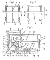
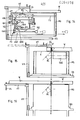
- FIG. 1 shows a plan view of a first embodiment of a sawing device according to the invention, and FIG. 2 also shows a plan view, but with the work table rotated through 90 °; 3 shows a side view of the sawing device; Fig. 4 is a front view and Fig. 5 is a view of the sawing device from the rear 6 and 7 are schematic side views of a further sawing device with a cable-operated lifting gear in the raised working position or in the lowered rest position; 8, 9 as well as FIGS.
- the work table 1 to 5 are formed by a work table 1, the saw unit 2 with the saw blade 3, the machine frame 4 supporting the work table 1, a fixed base frame 5 and a stop bar 6.
- the work table I or the - the work table supporting machine frame 4 is together with the saw unit 2 can be rotated about a vertical axis 7 relative to the fixed base frame 5 and can be locked in the desired positions relative to the base frame 5.
- the saw unit 2 or the saw blade 3 of the same can be adjusted in height relative to the work table 1 and can be moved in the horizontal direction in the machine frame 4.
- the stop bar 6 is connected directly to the base frame 5 via corresponding support rails 8 and 9.
- the work table 1 is rectangular in plan view, as can be seen in particular from FIGS. 1 and 2.
- the base frame 5 can expediently be square in plan view, it having proven expedient for reasons of stability to make the side length of the base frame 5 greater than the width of the work table, but less than the length of the work table 1.
- the vertical axis of rotation 7 is offset off-center against the stop bar 6 with respect to the longitudinal extent of the work table 1. However, this vertical axis of rotation 7 travels through the center of the base frame 5.
- abatweilrinEe 10 and 11 are provided coaxially with the vertical axis of rotation 7. These Abatützrings can also be used for precise angle adjustment if they have an angle mark and corresponding reference markings.
- the machine frame 4 supporting the work table 1 essentially consists of four support columns 12 which are arranged at the corners of the machine frame 4. These supporting columns 12 are connected to the bearing body 15 by means of corresponding connecting parts and struts 14 guided radially outward from the axis of rotation 7.
- the base frame 5 also expediently consists of a hanger body 16 and struts 17 which are guided in an etrahlon shape and end in feet 18.
- the work table 1 has a slot 19 on its longitudinal center line for the saw blade 3 to pass through.
- the arrangement of this saw bit 19 along the longitudinal center line results in an equally large support for the workpieces on both sides of the saw blade during cross cutting and There is enough space after both sots to also see broader workpieces or to cut them in the longitudinal direction.
- the Bägaaggregaa 2 is held on horizontal guide axes 20 within the machine seat 4.
- the height adjustment of the saw blade 3 or the entire suction unit 2 and the displacement of the suction unit 2 in the cutting direction can be done in various ways, both manually and mechanically.
- a manual adjustment can be carried out.
- the saw unit 2 is pivoted upwards about the axis 22, wroboi the saw blade 3 is guided over the surface of the work table 1. As the pulling lever 21 is pulled further, the saw unit is moved in the sonite direction within the machine tunnel 4, so that the cut can be carried out accordingly 24.
- This spring balancer 23 is tensioned accordingly when the saw unit 2 is pulled forward, the saw unit 2 falling back into its rest position after releasing the pull lever 21 and the spring balancer 23 bringing the saw unit back into the rear rest position.
- the like the pull lever 21 can be held in a certain position, so that the saw blade can be fixed at a desired extension height i E t .
- a display rod 25 is provided, which can be pivoted int with respect to the fixed part 51 together with the saw unit 2. It could then be fixed to it stahandeu Tesil 51 an English-speaking scale. be attached.
- a displaceable, but lockable stop can also be attached to this part of the standing part 51, which can be moved in a horizontal direction together with the sawing unit 2, in order thereby to limit the extension of the saw blade 3 when the saw unit 2 is pulled forward.
- the saw unit is additionally pivoted about a horizontal axis running parallel to the guide rails 20.
- the saw unit 2 is fastened to two flanges 26 and 27 arranged at a distance from one another.
- Arc-shaped slots 28 are provided in these flanges, into which the fastening screws 29 of the saw unit 2 engage. After loosening these fastening screws 29, a corresponding angular installation can be carried out, these fastening screws 29 then being tightened again.
- the stop bar 6 is connected directly to the base frame 5, specifically via support rails 8 and 9.
- the support rails 9 are conceivable in height on supports 30 which are connected directly to the base frame 5, for which purpose the shown embodiment examples of longitudinal bolts 31 are provided by corresponding fastening screws 32 are passed through.
- the mounting rails 9 are then adjusted in the horizontal direction bar, so that the Anshilagiciste 6 can be adjusted according to the required distance to the saw blade.
- the stop power 6 projects beyond the support rails 8 in the direction of the work table surface, so that a relatively precise closure to the work table. 1 can take place. This makes it possible to use the stop for correspondingly thin workpieces.
- the stop bar 6 has a cutout 35 for the passage of the saw blade 3 in the cutting direction.
- the stop bar 6 Due to the special construction of the stop bar 6 and the support rails 8 and 9, there is the possibility that the support rails 8 receiving the stop bars 6 can be lowered to the level of the work table height 1 outside the same.
- the stop power 6 is then turned through 180 °, so that the stop end then projects beyond the upper limit of the mounting rails 8.
- a corresponding extension of the work table is possible, which has a positive effect when relatively wide workpieces are to be separated in the longitudinal direction. So that an exact setting of the stop members is possible even in such a case, the stop bar is provided with a corresponding recess through which the support rails 3 can lead.
- the stop bar 6 is thus adjustable in the longitudinal direction of the support rails 8 and can be firmly stuck to them in the appropriate positions, this adjustability compared to the support brackets 8 also being given in the position of the stop bar shown in FIG. 3.
- the construction of the sawing device takes up very little height, so that this sawing device can be used as a table model. Due to the holes provided in the stand feet 18, it is also possible to add an additional base or individual feet here.
- the stop bar 6 is shown in the outermost position, the support rails 8 also being fully extended in the direction of the work table 1. It is of course possible here to set the stop bar 6 alone or together with the trassions 3 to any desired distance from the seat 19. 1 and 2 it can be seen that long workpieces are aligned in the same position with each type of processing by the measures according to the invention, especially since the stop bar 6 is connected to the fixed basic position 5 and therefore always has the same longitudinal alignment. Through a simple adjustability of the entire work table 2 or the machine frame 4 supporting the work table 2, a variety of possible uses can be created with such a sawing device.
- the work table can also be shortened accordingly, since there is basically the possibility that the saw blade dips into the workpiece from below. As a result, the full displacement length of the saw blade in the horizontal direction can be used.
- the exemplary embodiment shown is particularly for a worker machine suitable.
- Salobstverstädndlch the corresponding measures according to the invention can also be used with larger sowing weights by appropriate design changes, that is to say also with those in which the adjustment possibilities of the work table 1 and the saw unit 2 are carried out fully automatically.
- the basic principle then always remains the same, namely that there is a stop connected to the base frame, against which the entire work table including the saw unit is adjusted.
- the saw unit SAG is mounted on guides F1 within a supporting frame TG so as to be vertically movable in the sense of the infeed movement.
- the support frame tG 'in turn is mounted on the machine frame MG by means of guides F2 in the sense of a feed movement with respect to the work table 1 horizontally between the raised starting working position indicated in FIG. 6 and a final working position, not shown, shifted to the right.
- a hoist gear HGT with hoist rope ZS and several deflection pulleys U which are mounted on the support frame TG, causes the saw unit to be lifted from the lower rest position according to Fig.
- the restraint device RH with its tension spring acts not only on the support frame TG via a further tension cable ZS1 with its own deflecting roller Ul, but also on the vertical direction as a result of the deflection on top of the saw unit SAG.
- the spring-lifting energy store of the restraint device simultaneously forms a relief device which compensates for the weight of the saw unit to the intended extent, but not with a stroke-independent difference, because the restraint spring provides a stroke-dependent support force.
- a differential gear AGT in the form of a double-link toggle lever mechanism KNH, with which the actuator is coupled, takes the place of a lifting gear with a lifting force proportional to the actuating force, which is also constant with a constant actuating force.
- the saw unit SAG is pivotally mounted about a horizontal axis X by means of a link L and is connected to its own relief device EV, the latter having a torsion or winding spring FT as the lifting energy store.
- the effective transmission ratio of the differential is shown in FIGS. 8 and 9 as a product of the known power transmission function of a toggle lever mechanism with the cosine of the stroke position angle a of the handlebar L measured against the horizontal.
- This overall transmission ratio can be determined by suitable dimensioning and choice of the Movement angle ranges of the various links are easily dimensioned so that an approximately constant partial compensation of the angle-proportional change in the supporting force of the relief device EV is achieved.
- the actuator then has a substantially constant differential force during the lifting process overcome, which makes operation much easier, especially in the case of manual operation.
- a welcome simplification of this design is also the vertical guidance of the saw unit with the aid of a simple swivel bearing in the axis X.
- the arrangement according to FIGS. 8 and 9 can easily be used in an overall arrangement according to FIG. 6 instead of the vertical guidance and lifting gear there, whereby however, special restraint is to be provided using a simple tension spring.
- the lever-lifting movement guide of the saw unit can be configured by arranging further pairs of links in the sense of a parallelogram guide, whereby an annoying tilting movement of the saw unit during lifting is eliminated.
- the saw unit can also perform a precise vertical movement here if the stop (see ASL in FIG. 6) is designed as a single-acting vertical guide with which the saw unit is in contact during its vertical and any swiveling movement.
- the saw unit or the corresponding drive unit on the one hand and the saw blade on the other hand is pivotably mounted about a horizontal axis X, the latter in the entire pivoting range approximately above the common center of gravity of the saw unit and saw blade existing arrangement.
- the mounting of the saw unit SAG with its support frame TG on vertical and horizontal guides F1 and F2 essentially corresponds to the arrangement according to FIG. 6.
- the reference numerals for this and for other matching parts therefore correspond to the above illustration.
- a differential gear AGT is provided with a double lever member DHG, the lever arms HA1 and HA2 of which are arranged at an appropriately selected angle to one another.
- the lever arm HA1 engages, for example, via a roller-shaped transmission element at point P1 of the saw unit, while the lever arm HA2 is coupled at P2 to the horizontally movable actuator BG.
- the double link itself is pivotally mounted at P3 with a horizontal axis on the support frame TG.
- an overall transmission ratio of the differential gear can also be achieved here, which corresponds approximately linearly with respect to the movement or the horizontal movement of the actuating member BG during the lifting movement.
- This overall transmission ratio is evidently determined by the product of the vertical projection of the lever arm HA2 or the vertical projection of the lever arm HA1, ie by the product of the corresponding angle functions and lever arm lengths.
- a relief device can be designed in a simple manner, for example, as an orsion spring acting in the X axis.
- a retention device RH with a winding tension spring which holds the support frame TG at the stop ASL, ensures that the starting stop position of the saw unit according to FIG. 14 is maintained during the lifting movement.
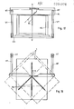
- FIGS. 14 to 18, in particular also shown in FIG. 18, indicate a pivotable arrangement of the saw unit with its machine frame MG about a vertical axis VV in relation to a base frame GG.
- the base frame is connected to vertical supports VT for a stop bar AL, which in turn is connected to the vertical supports VT via horizontal supports HT.
- the vertical supports are mounted in the manner indicated in terms of height with respect to the base frame (see FIGS. 15 and 16), while the horizontal supports are mounted horizontally displaceable at the upper ends of the vertical supports. This makes it possible to achieve a large number of working positions for the stop bar when machining different workpieces W, in particular also a support which is extended towards the rear for particularly extensive workpieces according to FIG. 16 :.
- the stop bar is to be used with its horizontal supports in a reversible position in the guides on the vertical supports and provided with appropriate stop elements on both sides of the horizontal supports.
- the stop elements on both sides can have different vertical dimensions, with which different workpiece thicknesses can be taken into account.
- the stop bar can easily be raised further from the lowered basic position according to FIGS. 15 and 17 and thus possibly also arranged on different sides of the saw blade.
- the latter as schematically indicated in FIGS. 15 to 17, is pivotally mounted in the usual way about a horizontal axis parallel to the plane of the sheet, for which purpose a corresponding joint arrangement is provided in the holder of the saw unit SAG (not shown).
- FIG. 18 shows the swiveling of the work table 1 with the machine frame MG without being impeded by the vertical supports VT connected to the base frame.
Landscapes
- Engineering & Computer Science (AREA)
- Mechanical Engineering (AREA)
- Life Sciences & Earth Sciences (AREA)
- Wood Science & Technology (AREA)
- Forests & Forestry (AREA)
- Sawing (AREA)
- Confectionery (AREA)
- Dicing (AREA)
Applications Claiming Priority (2)
| Application Number | Priority Date | Filing Date | Title |
|---|---|---|---|
| AT631880 | 1980-12-24 | ||
| AT6318/80 | 1980-12-24 |
Related Child Applications (1)
| Application Number | Title | Priority Date | Filing Date |
|---|---|---|---|
| EP84104154.4 Division-Into | 1984-04-12 |
Publications (2)
| Publication Number | Publication Date |
|---|---|
| EP0054978A1 true EP0054978A1 (fr) | 1982-06-30 |
| EP0054978B1 EP0054978B1 (fr) | 1985-04-24 |
Family
ID=3585096
Family Applications (2)
| Application Number | Title | Priority Date | Filing Date |
|---|---|---|---|
| EP81110785A Expired EP0054978B1 (fr) | 1980-12-24 | 1981-12-24 | Dispositif de sciage |
| EP84104154A Withdrawn EP0125503A2 (fr) | 1980-12-24 | 1981-12-24 | Dispositif à scier |
Family Applications After (1)
| Application Number | Title | Priority Date | Filing Date |
|---|---|---|---|
| EP84104154A Withdrawn EP0125503A2 (fr) | 1980-12-24 | 1981-12-24 | Dispositif à scier |
Country Status (3)
| Country | Link |
|---|---|
| EP (2) | EP0054978B1 (fr) |
| AT (1) | ATE12906T1 (fr) |
| DE (1) | DE3170214D1 (fr) |
Cited By (2)
| Publication number | Priority date | Publication date | Assignee | Title |
|---|---|---|---|---|
| DE202011101566U1 (de) * | 2011-05-30 | 2012-09-05 | Wilhelm Altendorf Gmbh & Co. Kg | Holzbearbeitungsmaschine mit Sägeblatt-Schnellabsenkung |
| CN120962424A (zh) * | 2025-10-17 | 2025-11-18 | 南通旭德科技有限公司 | 一种重力补偿的高精度工业加工用数控机床 |
Families Citing this family (1)
| Publication number | Priority date | Publication date | Assignee | Title |
|---|---|---|---|---|
| DE8605687U1 (de) * | 1986-03-01 | 1986-06-12 | Josef Scheppach Maschinenfabrik Gmbh & Co, 8873 Ichenhausen | Holzbearbeitungsmaschine |
Citations (17)
| Publication number | Priority date | Publication date | Assignee | Title |
|---|---|---|---|---|
| US1359394A (en) * | 1917-04-28 | 1920-11-16 | Jr James Marshall Leaver | Intermittent and oscillatory rotary cut-off saw-machine |
| US1584086A (en) * | 1922-12-11 | 1926-05-11 | Lester T Fonda | Sawing machine |
| US1796697A (en) * | 1930-03-31 | 1931-03-17 | Thomas F White | Woodworking machine |
| US1825104A (en) * | 1930-08-08 | 1931-09-29 | Charles A Staeheli | Saw table |
| DE807641C (de) * | 1948-10-02 | 1951-07-02 | Carl Fischer | Kreissaege mit pendelndem Saegeblatt |
| CH277404A (de) * | 1949-08-24 | 1951-08-31 | Mueller Max | Kettenstemm-Maschine, deren Antriebselektromotor durch einen im Maschinenfuss gelagerten, entgegen der Wirkung einer Feder verschwenkbaren Hebel abgestützt ist. |
| CH300371A (de) * | 1952-04-21 | 1954-07-31 | Soehne Jb Boegli | Doppelkreissäge. |
| US2719547A (en) * | 1952-03-01 | 1955-10-04 | Gjerde Arne | Universally adjustable underbench saw |
| US2786500A (en) * | 1954-03-26 | 1957-03-26 | Joseph G Unterfranz | Combination carrying case and table for portable power tool |
| US2792032A (en) * | 1955-09-30 | 1957-05-14 | John V Olsen | Swinging power saw |
| US2945516A (en) * | 1956-12-31 | 1960-07-19 | Yuba Cons Ind Inc | Tilting arbor table saw with coaxial control of elevation and tilt |
| US3139124A (en) * | 1962-09-28 | 1964-06-30 | William H B Hoff | Swingable mount for power saws |
| CH409356A (de) * | 1962-02-26 | 1966-03-15 | J Bruendler Arthur | Kreissäge |
| GB1161584A (en) * | 1966-02-04 | 1969-08-13 | Arrigo Pecchioli | Improvements in or relating to Copy Milling Machines |
| DE1528003A1 (de) * | 1965-03-25 | 1970-01-15 | Reich Maschf Gmbh Karl | Vorrichtung zum Bearbeiten von plattenfoermigen Werkstuecken |
| DE1628878A1 (de) * | 1967-03-07 | 1970-02-05 | Erwin Jenkner | Hub- und Senkeinrichtung des Kreissaegeblattes einer automatischen Untertischkreissaege |
| DE2903574A1 (de) * | 1978-03-22 | 1979-09-27 | Irion W & P | Kapp-kreissaege |
-
1981
- 1981-12-24 DE DE8181110785T patent/DE3170214D1/de not_active Expired
- 1981-12-24 AT AT81110785T patent/ATE12906T1/de active
- 1981-12-24 EP EP81110785A patent/EP0054978B1/fr not_active Expired
- 1981-12-24 EP EP84104154A patent/EP0125503A2/fr not_active Withdrawn
Patent Citations (17)
| Publication number | Priority date | Publication date | Assignee | Title |
|---|---|---|---|---|
| US1359394A (en) * | 1917-04-28 | 1920-11-16 | Jr James Marshall Leaver | Intermittent and oscillatory rotary cut-off saw-machine |
| US1584086A (en) * | 1922-12-11 | 1926-05-11 | Lester T Fonda | Sawing machine |
| US1796697A (en) * | 1930-03-31 | 1931-03-17 | Thomas F White | Woodworking machine |
| US1825104A (en) * | 1930-08-08 | 1931-09-29 | Charles A Staeheli | Saw table |
| DE807641C (de) * | 1948-10-02 | 1951-07-02 | Carl Fischer | Kreissaege mit pendelndem Saegeblatt |
| CH277404A (de) * | 1949-08-24 | 1951-08-31 | Mueller Max | Kettenstemm-Maschine, deren Antriebselektromotor durch einen im Maschinenfuss gelagerten, entgegen der Wirkung einer Feder verschwenkbaren Hebel abgestützt ist. |
| US2719547A (en) * | 1952-03-01 | 1955-10-04 | Gjerde Arne | Universally adjustable underbench saw |
| CH300371A (de) * | 1952-04-21 | 1954-07-31 | Soehne Jb Boegli | Doppelkreissäge. |
| US2786500A (en) * | 1954-03-26 | 1957-03-26 | Joseph G Unterfranz | Combination carrying case and table for portable power tool |
| US2792032A (en) * | 1955-09-30 | 1957-05-14 | John V Olsen | Swinging power saw |
| US2945516A (en) * | 1956-12-31 | 1960-07-19 | Yuba Cons Ind Inc | Tilting arbor table saw with coaxial control of elevation and tilt |
| CH409356A (de) * | 1962-02-26 | 1966-03-15 | J Bruendler Arthur | Kreissäge |
| US3139124A (en) * | 1962-09-28 | 1964-06-30 | William H B Hoff | Swingable mount for power saws |
| DE1528003A1 (de) * | 1965-03-25 | 1970-01-15 | Reich Maschf Gmbh Karl | Vorrichtung zum Bearbeiten von plattenfoermigen Werkstuecken |
| GB1161584A (en) * | 1966-02-04 | 1969-08-13 | Arrigo Pecchioli | Improvements in or relating to Copy Milling Machines |
| DE1628878A1 (de) * | 1967-03-07 | 1970-02-05 | Erwin Jenkner | Hub- und Senkeinrichtung des Kreissaegeblattes einer automatischen Untertischkreissaege |
| DE2903574A1 (de) * | 1978-03-22 | 1979-09-27 | Irion W & P | Kapp-kreissaege |
Cited By (2)
| Publication number | Priority date | Publication date | Assignee | Title |
|---|---|---|---|---|
| DE202011101566U1 (de) * | 2011-05-30 | 2012-09-05 | Wilhelm Altendorf Gmbh & Co. Kg | Holzbearbeitungsmaschine mit Sägeblatt-Schnellabsenkung |
| CN120962424A (zh) * | 2025-10-17 | 2025-11-18 | 南通旭德科技有限公司 | 一种重力补偿的高精度工业加工用数控机床 |
Also Published As
| Publication number | Publication date |
|---|---|
| ATE12906T1 (de) | 1985-05-15 |
| EP0054978B1 (fr) | 1985-04-24 |
| EP0125503A2 (fr) | 1984-11-21 |
| DE3170214D1 (en) | 1985-05-30 |
Similar Documents
| Publication | Publication Date | Title |
|---|---|---|
| DE69301513T2 (de) | Motorisiertes schwenkbares Werkzeug mit Tisch | |
| EP0188654B1 (fr) | Dispositif de suspension pour charges mobiles, notamment pour canalisations et objets similaires | |
| DE2915288C2 (de) | Kaltkreissäge mit einem schwenkbaren Sägeblattarm | |
| EP0706769A2 (fr) | Dispositif de réglage de la hauteur d'un plan de travail d'une table ou analogue | |
| DE2443373A1 (de) | Lochstanze oder knabberpresse mit werkzeugwechsler | |
| DE3413047A1 (de) | Messvorrichtung | |
| DE69301798T2 (de) | Schwenkbarer Tisch mit Motorwerkzeug | |
| EP0615807B1 (fr) | Scie de précision à table ayant une rigidité de torsion améliorée des éléments de structure | |
| EP3658311A1 (fr) | Installation de traitement d'éléments structuraux d'aéronef | |
| DE4004705C2 (fr) | ||
| DE9307192U1 (de) | Stationär betriebene Auslegerkreissäge | |
| EP0054978A1 (fr) | Dispositif de sciage | |
| DE20023378U1 (de) | Format-Säge | |
| DE2610774C3 (de) | Abkant- bzw. Biegebank für Bleche o.dgl | |
| DE4033037C2 (fr) | ||
| EP0090171A2 (fr) | Dispositif pour le mortaisage du bois, du bois composé et de matériaux similaires | |
| DE3400298A1 (de) | Sicherheitseinrichtung fuer elektronische bohrmaschinen | |
| DE3544058C2 (de) | Sägeeinrichtung zum Zuschneiden von Profilleisten o.dgl. | |
| EP0603496A1 (fr) | Guide à galets et dispositif de coulissement | |
| DE3727759A1 (de) | Vorrichtung zum heben und senken und/oder neigen von gegenstaenden, insbesondere einer tischplatte, einem zeichenbrett oder dergleichen | |
| EP0299155B1 (fr) | Scie circulaire à froid ayant un pivot de levier de lame de scie ajustable transversalement par rapport à la direction de chargement des pièces à travailler | |
| EP1008550B1 (fr) | Agencement mécanique pour limiter le mouvement de plate-formes de travail | |
| DE2227406A1 (de) | Fahrbare drehleiter | |
| DE102004030269B4 (de) | Tischkreissäge | |
| DE3542989C2 (fr) |
Legal Events
| Date | Code | Title | Description |
|---|---|---|---|
| PUAI | Public reference made under article 153(3) epc to a published international application that has entered the european phase |
Free format text: ORIGINAL CODE: 0009012 |
|
| AK | Designated contracting states |
Designated state(s): AT BE CH DE FR GB IT LI LU NL SE |
|
| 17P | Request for examination filed |
Effective date: 19821218 |
|
| ITF | It: translation for a ep patent filed | ||
| GRAA | (expected) grant |
Free format text: ORIGINAL CODE: 0009210 |
|
| AK | Designated contracting states |
Designated state(s): AT BE CH DE FR GB IT LI LU NL SE |
|
| PG25 | Lapsed in a contracting state [announced via postgrant information from national office to epo] |
Ref country code: NL Effective date: 19850424 Ref country code: BE Effective date: 19850424 |
|
| REF | Corresponds to: |
Ref document number: 12906 Country of ref document: AT Date of ref document: 19850515 Kind code of ref document: T |
|
| PG25 | Lapsed in a contracting state [announced via postgrant information from national office to epo] |
Ref country code: SE Effective date: 19850430 |
|
| REF | Corresponds to: |
Ref document number: 3170214 Country of ref document: DE Date of ref document: 19850530 |
|
| ET | Fr: translation filed | ||
| PG25 | Lapsed in a contracting state [announced via postgrant information from national office to epo] |
Ref country code: DE Effective date: 19850902 |
|
| NLV1 | Nl: lapsed or annulled due to failure to fulfill the requirements of art. 29p and 29m of the patents act | ||
| PG25 | Lapsed in a contracting state [announced via postgrant information from national office to epo] |
Ref country code: AT Effective date: 19851224 |
|
| PG25 | Lapsed in a contracting state [announced via postgrant information from national office to epo] |
Ref country code: LU Free format text: LAPSE BECAUSE OF NON-PAYMENT OF DUE FEES Effective date: 19851231 Ref country code: LI Effective date: 19851231 Ref country code: CH Effective date: 19851231 |
|
| PLBE | No opposition filed within time limit |
Free format text: ORIGINAL CODE: 0009261 |
|
| STAA | Information on the status of an ep patent application or granted ep patent |
Free format text: STATUS: NO OPPOSITION FILED WITHIN TIME LIMIT |
|
| 26N | No opposition filed | ||
| GBPC | Gb: european patent ceased through non-payment of renewal fee | ||
| PG25 | Lapsed in a contracting state [announced via postgrant information from national office to epo] |
Ref country code: FR Free format text: LAPSE BECAUSE OF NON-PAYMENT OF DUE FEES Effective date: 19860829 |
|
| REG | Reference to a national code |
Ref country code: CH Ref legal event code: PL |
|
| REG | Reference to a national code |
Ref country code: FR Ref legal event code: ST |
|
| PG25 | Lapsed in a contracting state [announced via postgrant information from national office to epo] |
Ref country code: GB Effective date: 19881121 |