EP0706769A2 - Dispositif de réglage de la hauteur d'un plan de travail d'une table ou analogue - Google Patents
Dispositif de réglage de la hauteur d'un plan de travail d'une table ou analogue Download PDFInfo
- Publication number
- EP0706769A2 EP0706769A2 EP95116005A EP95116005A EP0706769A2 EP 0706769 A2 EP0706769 A2 EP 0706769A2 EP 95116005 A EP95116005 A EP 95116005A EP 95116005 A EP95116005 A EP 95116005A EP 0706769 A2 EP0706769 A2 EP 0706769A2
- Authority
- EP
- European Patent Office
- Prior art keywords
- table top
- support frame
- parallel
- spring
- parallel link
- Prior art date
- Legal status (The legal status is an assumption and is not a legal conclusion. Google has not performed a legal analysis and makes no representation as to the accuracy of the status listed.)
- Withdrawn
Links
- 230000007246 mechanism Effects 0.000 claims description 9
- 230000006835 compression Effects 0.000 claims description 7
- 238000007906 compression Methods 0.000 claims description 7
- 230000008878 coupling Effects 0.000 claims description 4
- 238000010168 coupling process Methods 0.000 claims description 4
- 238000005859 coupling reaction Methods 0.000 claims description 4
- 230000000284 resting effect Effects 0.000 claims description 2
- 230000008901 benefit Effects 0.000 description 2
- 230000009467 reduction Effects 0.000 description 2
- 230000004308 accommodation Effects 0.000 description 1
- 230000006978 adaptation Effects 0.000 description 1
- 230000005540 biological transmission Effects 0.000 description 1
- 238000010276 construction Methods 0.000 description 1
- 230000001419 dependent effect Effects 0.000 description 1
- 230000004048 modification Effects 0.000 description 1
- 238000012986 modification Methods 0.000 description 1
- 238000004904 shortening Methods 0.000 description 1
Images


Classifications
-
- A—HUMAN NECESSITIES
- A47—FURNITURE; DOMESTIC ARTICLES OR APPLIANCES; COFFEE MILLS; SPICE MILLS; SUCTION CLEANERS IN GENERAL
- A47B—TABLES; DESKS; OFFICE FURNITURE; CABINETS; DRAWERS; GENERAL DETAILS OF FURNITURE
- A47B9/00—Tables with tops of variable height
-
- A—HUMAN NECESSITIES
- A47—FURNITURE; DOMESTIC ARTICLES OR APPLIANCES; COFFEE MILLS; SPICE MILLS; SUCTION CLEANERS IN GENERAL
- A47B—TABLES; DESKS; OFFICE FURNITURE; CABINETS; DRAWERS; GENERAL DETAILS OF FURNITURE
- A47B2200/00—General construction of tables or desks
- A47B2200/0035—Tables or desks with features relating to adjustability or folding
- A47B2200/005—Leg adjustment
- A47B2200/0056—Leg adjustment with a motor, e.g. an electric motor
Definitions
- the invention relates to a device for adjusting the working height of a table top or the like compared to a support frame with height locking means and parallel link guides, each having two parallel links and are arranged between the support frame and the table top or the like.
- the present invention has for its object to provide a device for adjusting the working height of a table top or the like, which allows a large height adjustment range, in which the height adjustment and subsequent locking can be done quickly and easily, and in which no walking of the table top or the like compared to the support frame in the plate level during the adjustment.
- This object is achieved according to the present invention in a device for adjusting the working height with two parallel linkages of the type mentioned in that the two parallel links on the one hand at two spaced, fixed articulation points on the support frame and on the other hand at two spaced articulation points one below the table top parallel to the plane the table top slidably guided guide element, the distance between the articulation points is smaller than the length of the parallel link, and that to fix the position of the table top in the horizontal plane relative to the support frame between the center of one of the parallel links and a fixed point on the table top a coupling link is arranged.
- the solution according to the invention has the great advantage that not only the task is fully accomplished, but that its structure is simple and cost-saving, and moreover, in a simple manner, a balance of the weight of the table top or the like, including objects or devices standing thereon possible is.
- two parallel link guides are preferably provided at a lateral distance from one another between the support frame and the table top or the like.
- the mutually corresponding parallel link and guide elements of the two parallel link guides are expediently connected to one another by traverses in order to avoid stability and tilting.
- a compensating tension spring is provided between the articulation points of the parallel link for each parallel link guide in such a way that the spring force acts in the lifting direction of the table top or the like.
- the compensating tension spring is preferably only designed for the weight compensation of the table top or the like, while a leg spring is provided for further weight compensation of objects, devices or the like resting on the table top in the region of the articulation points of the parallel links on the support frame, that is to say in the region of the lower articulation points.
- Both the compensating tension spring and the leg spring are preferably designed to be adjustable, on the one hand to set an initial basic position and, on the other hand, to take into account the different loading situations of the table top or the like.
- the height locking means for the device according to the invention are preferably designed as multi-disk brakes which lock the parallel links in the area of the upper articulation points. This is preferably done in that the multi-disc brake acts between the guide element and one of the parallel links.
- weight balancing arrangement for balancing the empty weight of the table top or for balancing objects placed thereon allows weight balancing only within certain limits. Further imbalances are usually only braked using the height locking device so that the table top does not move up or down when the weight changes.
- a particularly advantageous weight balancing device which allows sensitive, largely complete weight balancing over a wide range, is characterized according to an advantageous embodiment by a common balancing spring arrangement arranged transversely between the two parallel link guides in the supporting frame, with its two ends at a diagonal point of the parallel link guides attacks.
- This solution has the essential advantage that in a device with parallel link guides arranged on both sides of a support frame, only a single compensating spring arrangement is necessary, for which there is enough space to achieve large spring forces over a large spring stroke, because the transverse arrangement in the support frame allows one Accommodation in which a large-volume compensation spring does not interfere.
- the spring force of the compensating spring arrangement is preferably adjustable. This makes it possible to get one Weight compensation, for example, when the table top is unloaded or when the load is less. On the other hand, it is also possible to balance the weight of very heavy devices placed on the table top, for example devices with a weight of 50-80 kg.
- the force transmission between the compensating spring arrangement to the parallel link guides takes place via traction cables, which makes it possible to have the spring forces act exactly in the diagonal of the parallel link guides.
- Particularly compact conditions for the compensating spring arrangement result if it contains a compression spring, the ends of which are supported on linearly guided sliding elements, the traction cables being cross-coupled to the sliding elements.
- an adjustability of the spring force is particularly simple to carry out by providing a likewise linearly guided adjusting element whose distance from one of the sliding elements can be adjusted by a spindle and which is connected to one of the two pulling cables while the other pulling cable is connected to the other Sliding element is connected.
- the spindle drive expediently consists of a threaded spindle and a threaded bushing, the threaded spindle being mounted non-displaceably in the longitudinal direction on a guide rail connected to the table top, while the threaded bushing is coupled to the guide element.
- a further embodiment contains a spindle drive with an electric motor acting in the diagonal between two articulation points of the parallel links.
- this spindle drive serves at the same time as a height locking device, and weight compensation can usually be dispensed with.
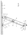
- FIGS. 2a and 2b which show more structural details, are somewhat more confusing.
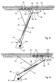
- a table top 11 or the like is to be continuously adjusted relative to a support frame 3 between a low height (FIG. 1b) and an extended position (FIG. 1a).
- Fig. 1b does not yet correspond to the lower end position, but this is shown in Fig. 2b.
- Two fixed articulation points or articulation axes 6a and 6b are arranged at a distance from one another on the support frame 3, and these articulation points 6a and 6b are coupled to two further articulation points 6c and 6d via parallel links 1 and 2.
- the upper articulation points 6c and 6d are arranged on a leg 4a of a guide element 4 which is guided so as to be displaceable parallel to the table top 11 in the plane of the table top.
- the parallel guidance is carried out by means of sliding pieces 4c arranged on a holder 4b in a Z-shaped guide rail 12.
- a coupling link 5 is provided, which is coupled at one end to a fixed articulation point 5 a on the table top 11 and at the other end to the center 5 b of the parallel link 1 is.
- a first isosceles triangle is formed between the articulation points 5a, 5b and 6a, while a second isosceles triangle is formed between the articulation points 5a, 5b and 6c, which ensures that when the articulation point 6a can be moved relative to the table top 11, the articulation point 5a and so that the table top 11 always occupies the same position with respect to the support frame 3 in the plane of the table top.
- a compensation tension spring 21 is provided between the articulation points 6a and 6d.
- the tensile force of this compensating tension spring 21 is adjustable in order to either adjust the compensation for an empty table top 11 or to take additional load on the table top 11 into account.
- a leg spring 22 is indicated in the region of the articulation point 6b, with which the load on the table top 11 is expediently compensated for in an adjustable manner.
- a clamping lever 15 is also indicated, with which a locking device for the adjusting device can be actuated in order to fix the position at any set height of the table top 11.
- the detailed structure of the locking device will be explained in detail later.
- Support frame in the present case consists of a bracket 3a, with which the entire device including parallel link guides and height locking means and attached table top 11 can be attached to a table base or the like or a cross member 10 of such a table frame.
- Fig. 2a shows that the height of the adjustment device is extremely low, and that the table top can be extended from this low position to the top position (see Fig. 2a).
- the entire parallel link mechanism is constructed as a largely closed unit, i.e. the two parallel links 1 and 2, which are only a relatively short distance apart, are designed as U-shaped profiles (see in particular the detailed illustration in Fig.
- the parallel links 1 and 2 of the parallel link guides of the overall mechanism lying next to one another are connected to one another by a crossbar 13, so that no tilting occurs during adjustment.
- the guide elements 4 are also connected to one another by a crossbar 14.
- the guide elements 4 are designed as U-profiles on both sides in order to ensure a stable mounting of the articulation points 6c and 6d.
- holders 4b are fastened which carry sliding pieces 4c at their ends (see also FIGS. 1a and 1b). These sliders 4c engage in the open area of the Z-shaped guide rails 12, which in turn are fastened to a corresponding support on which the table top 11 rests.
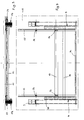
- the height locking means are constructed. They each consist of a multi-disc brake 17a or 17b, which are arranged in the region of the articulation points 6c and 6d.
- the disk packs are arranged in such a way that they fix the parallel link 1 with respect to one leg 4a of the guide element 4 in the braking state, so that the parallelogram of the parallel link guides can no longer deform.
- the articulation point or articulation axis 6c is constructed as a tube through which a threaded rod 23 is passed.
- the threaded rod 23 is fixed at the left end (in FIG. 5) by two nuts, while a clamping nut 24 is arranged at the right end is.
- the clamping lever 15 With the clamping nut 24, the clamping lever 15 is pivotally coupled, and by pivoting the clamping lever 15 about the axis of the threaded rod 23, the clamping nut 24 can be screwed onto the threaded rod 23 and thus the distance between the ends can be changed. As a result, the laminated cores of the multi-disc brakes 17a and 17b are clamped together in the braking position. Since the clamping lever 15 is arranged fairly close under the table top, the clamping nut 24 can normally only be rotated by 180 ° at a time. In the respective end position, however, the clamping lever can be pivoted about the axis of its pivot pin into the opposite position, so that clamping steps of 180 ° are possible in each case. This ensures that defined clamping positions for the multi-disc brakes 17a and 17b are achieved.
- the support frame 3 does not have to be a base frame, but it is also possible to screw the support frame 3 to a room wall or the like with a corresponding shortening of the table top 11.
- the sliding guide between the sliders 4c and the guide rail 12 can be designed differently, and it is also possible to provide other height locking means instead of the multi-disc brakes 17a and 17b.
- the weight compensation was carried out by a tension spring 21.
- a specific, further exemplary embodiment is to be described below.
- the compensating spring arrangement 21a shown in FIG. 7 consists of a sleeve 26 which is arranged transversely to the support frame 3, that is to say between the two parallel link guides, on a crossbar, in particular a cable duct.
- a compression spring 21b is arranged in the sleeve 26 between two sliding elements 27, 28 which can be displaced in the longitudinal direction of the sleeve 26.
- a traction cable 7 is fastened by means of a clamp 28a, which (seen in the drawing) is led out on the left side of the sleeve 26.
- a second traction cable 8 is fastened to an adjusting element 30 by means of clamping screws 30a and is led out from the right side (seen in the drawing) and connected to the traction cable 8 of FIG. 6.
- the adjusting element 30 is adjustable relative to the sliding element 27 by means of a threaded spindle 29, an actuating crank 29a being arranged on the threaded spindle.
- the two pull cables 7 and 8 engage - and this is only shown for the pull cable 8 in FIG. 6 - in the vicinity of the articulation point 6d of the parallel link guide, so that when the compression spring 21b is relaxed, the articulation point 6d is pulled diagonally to the articulation point 6a. so that a force for lifting the table top 11 is generated.
- the force of the compression spring 21b can be adjusted and thus the spring force exerted on the table top 11.
- the direction of the pull cables 7 and 8 takes place from the transverse direction of the compensating spring arrangement 21a in the longitudinal direction (direction of the parallel links 1, 2) via first deflecting rollers 18, while second deflecting rollers 19 ensure that the pull cable 7 or 8 engages approximately from the direction of the articulation point 6a, that is to say in the diagonal direction.
- the end of the pull cables 7, 8 is not connected to the articulation point 6d, but rather is shifted to the end of the parallel link 2 in the region of the articulation point.
- a compensating spring arrangement 21a with a compression spring was shown.
- a common tension spring in the transverse direction of the support frame 3 and to have the ends of the tension spring act directly on corresponding tension cables 7, 8.
- Such a compensating spring arrangement requires a greater overall length and cannot be easily adjusted in the spring force.
- the weight-balancing device is able to balance large table loads (for example up to 50-80 kg), there is also the risk that when such a load is removed, the table top 11 will move upwards with great force when the locking mechanism is released .
- the locking mechanism not only consists of a continuously acting, spring-loaded parking brake, but also contains an additional, spring-loaded locking mechanism, which contains a spring-loaded pin 15a and a large number of locking holes 15b in the guide rail 12 (only indicated in FIGS. 1a and 1b) .
- the latching mechanism 15a, 15b initially remains in engagement, only when a larger stroke is exerted by the actuating lever 15 is the latching mechanism also released, and the height of the table top 11 can then be adjusted.
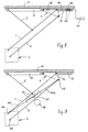
- FIG. 8 now shows a further embodiment of the present invention, which is constructed in the holder of the table top 11 relative to the support frame 3 in a manner similar to the embodiments described above. For this reason, similar parts are given the same reference numerals.
- the device according to FIG. 8 does not contain any height locking means in the form of a multi-disc brake, such as the embodiments according to FIGS. 3 to 5, but instead a spindle drive with a threaded spindle 40 and a threaded bush 42 is provided between the table top 11 and the guide element 4.
- the threaded spindle 40 is mounted in the guide rail 12 so that it cannot move in the axial direction, which is indicated by indicated stops 43 on the guide rail 12 and a stop bush 44 mounted between them, the stop bush 44 being connected to the threaded spindle 40.
- the guide element 4 can thus be moved relative to the guide rail 12 and thus the table top 11, whereby the table top 11 is raised or lowered by means of the parallel link guide (parallel link 1, 2) and the coupling link 5.
- the threaded spindle 40 can be driven either by means of a crank 41 by hand or by an electric motor (not shown) with a reduction gear. Since the spindle drive can be made self-locking, a further height locking device is not required, so that the table top 11 is securely locked in any position relative to the support frame 3.
- FIG. 9 now shows a further embodiment in which a spindle drive does not engage between the guide element 4 and the table top 11 or the guide rail 12, as in the exemplary embodiment according to FIG. 8, but in a diagonal of the parallel link guide.
- 9 shows an arrangement which acts between the articulation points 6a and 6d of the two parallel links 1, 2 and which consists of two counter-rotating threaded spindles 45a and 45b, counter-rotating threaded nuts 46 cooperating therewith, a gear 47 and an electric motor 48.
- the remaining function of the parallel link guide with the two parallel link 1, 2 works in the same manner as described in the above embodiments.
- the guide element 4 can be guided on the guide rail 12 either by sliding pieces or, as in FIGS. 8 and 9, in an indicated guide slot 59.
Landscapes
- Machine Tool Units (AREA)
- Workshop Equipment, Work Benches, Supports, Or Storage Means (AREA)
Applications Claiming Priority (4)
| Application Number | Priority Date | Filing Date | Title |
|---|---|---|---|
| DE19944436839 DE4436839A1 (de) | 1994-10-14 | 1994-10-14 | Vorrichtung zum Verstellen der Arbeitshöhe einer Tischplatte oder dergleichen |
| DE4436839 | 1994-10-14 | ||
| DE1995117825 DE19517825A1 (de) | 1995-05-18 | 1995-05-18 | Vorrichtung zum Verstellen der Arbeitshöhe einer Tischplatte oder dergleichen |
| DE19517825 | 1995-05-18 |
Publications (2)
| Publication Number | Publication Date |
|---|---|
| EP0706769A2 true EP0706769A2 (fr) | 1996-04-17 |
| EP0706769A3 EP0706769A3 (fr) | 2000-09-06 |
Family
ID=25941065
Family Applications (1)
| Application Number | Title | Priority Date | Filing Date |
|---|---|---|---|
| EP95116005A Withdrawn EP0706769A3 (fr) | 1994-10-14 | 1995-10-11 | Dispositif de réglage de la hauteur d'un plan de travail d'une table ou analogue |
Country Status (2)
| Country | Link |
|---|---|
| US (1) | US5649493A (fr) |
| EP (1) | EP0706769A3 (fr) |
Cited By (4)
| Publication number | Priority date | Publication date | Assignee | Title |
|---|---|---|---|---|
| CN106175094A (zh) * | 2016-08-31 | 2016-12-07 | 浙江安吉护童家具有限公司 | 可自由升降的桌面板角度升降器及学习桌 |
| US9668572B2 (en) | 2014-04-14 | 2017-06-06 | Ergotron, Inc. | Height adjustable desktop work surface |
| US10542817B2 (en) | 2015-09-24 | 2020-01-28 | Ergotron, Inc. | Height adjustable device |
| US10602840B2 (en) | 2015-10-08 | 2020-03-31 | Ergotron, Inc. | Height adjustable table |
Families Citing this family (24)
| Publication number | Priority date | Publication date | Assignee | Title |
|---|---|---|---|---|
| AU3026899A (en) * | 1998-04-14 | 1999-11-01 | Sis International A/S | A frame structure for a supporting member, such as a table top |
| GB2337692B (en) | 1998-05-20 | 2001-10-17 | Malcolm Cole Ltd | Ajustable leg table |
| US5979521A (en) * | 1999-01-22 | 1999-11-09 | Delta International Machinery Corp. | Adjustment mechanism |
| JP3859071B2 (ja) * | 2002-11-25 | 2006-12-20 | ジーイー・メディカル・システムズ・グローバル・テクノロジー・カンパニー・エルエルシー | 平行リンク型テーブルおよび断層画像撮影装置 |
| CZ13495U1 (cs) * | 2003-05-16 | 2003-07-14 | Pavel Truksa | Zařízení pro polohovou fixaci skládacích stavebnicových systémů |
| CA2736850C (fr) | 2010-04-12 | 2017-09-26 | Baral Holdings Corp. | Systeme de plan de travail a hauteur reglable |
| WO2013176690A1 (fr) | 2012-05-24 | 2013-11-28 | Gemmy Industries Corporation | Plateforme de bureau réglable |
| US20140144352A1 (en) * | 2012-11-24 | 2014-05-29 | Christopher John Roberts | Portable and adjustable desktop workstation |
| WO2016209513A1 (fr) * | 2015-06-24 | 2016-12-29 | Ergotron, Inc. | Surface de travail de bureau réglable en hauteur |
| JP6602953B2 (ja) * | 2015-09-18 | 2019-11-06 | 楽歌人体工学科技股▲分▼有限公司 | 昇降作業台 |
| CN105901923B (zh) * | 2016-06-03 | 2017-10-24 | 佛山市迪赛纳科技有限公司 | 升降机构及包含升降机构的升降工作台和工作台升降方法 |
| US10285496B2 (en) | 2016-06-03 | 2019-05-14 | Designa Inc. | Height adjustment mechanism and platform |
| DE102016112119B4 (de) * | 2016-07-01 | 2023-09-14 | Grammer Aktiengesellschaft | Federungsvorrichtung |
| USD841369S1 (en) | 2016-08-01 | 2019-02-26 | Designa Inc. | Height adjustment platform |
| CN206586583U (zh) * | 2016-10-21 | 2017-10-27 | 深圳米乔科技有限公司 | 一种升降桌 |
| US10111518B2 (en) | 2016-11-23 | 2018-10-30 | Knape & Vogt Manufacturing Company | Adjustable ergonomic workstation |
| US10258148B1 (en) | 2017-05-02 | 2019-04-16 | Brunswick Corporation | Convertible sit-to-stand desk |
| USD850172S1 (en) | 2017-05-08 | 2019-06-04 | Designa Inc. | Mobile height-adjustable work station |
| USD851852S1 (en) | 2017-05-08 | 2019-06-18 | Designa Inc. | Mobile height-adjustable work station |
| USD843137S1 (en) | 2017-08-21 | 2019-03-19 | Designa Inc. | Height adjustable workstation |
| DE102018126098A1 (de) * | 2018-10-19 | 2020-04-23 | Kesseböhmer Produktions GmbH & Co. KG | Höhenverstellbarer Tisch |
| CN109043813A (zh) * | 2018-10-23 | 2018-12-21 | 冠达星股份有限公司 | 高度可调节的电脑桌 |
| US11666143B2 (en) * | 2019-05-14 | 2023-06-06 | Fellowes Inc. | Multi-positional articulating ergonomic device with modular features |
| CN110301746A (zh) * | 2019-07-18 | 2019-10-08 | 广州典赞家具有限公司 | 一种便于调节使用的办公桌 |
Citations (1)
| Publication number | Priority date | Publication date | Assignee | Title |
|---|---|---|---|---|
| DE7640895U1 (fr) | 1976-12-29 | 1977-04-21 | Stapper, Johann, 5023 Weiden |
Family Cites Families (16)
| Publication number | Priority date | Publication date | Assignee | Title |
|---|---|---|---|---|
| US2124754A (en) * | 1936-05-27 | 1938-07-26 | Ternstedt Mfg Co | Seat adjuster |
| US2206788A (en) * | 1939-10-13 | 1940-07-02 | Meacham George | Elevating truck |
| CH259392A (de) * | 1948-05-15 | 1949-01-31 | Krayenbuehl Silvio | Vorrichtung an Tischen zur Veränderung der Tischplattenhöhe. |
| US2545515A (en) * | 1948-07-24 | 1951-03-20 | Le Febure Corp | Vertically adjustable table for office appliances |
| US2645538A (en) * | 1948-12-30 | 1953-07-14 | Wilson Jones Co | Posting stand |
| DE1405795A1 (de) * | 1960-10-03 | 1968-12-12 | Brendel Friedrich | Gefederter Fahrzeugsitztraeger geringer Bauhoehe |
| US3339906A (en) * | 1965-09-10 | 1967-09-05 | Persson Bror Gote | Resilient support for seats |
| DE2535042A1 (de) * | 1975-08-06 | 1977-02-24 | August Brede | Stufenlos hoehenverstellbarer tisch |
| US4018487A (en) * | 1976-03-25 | 1977-04-19 | Keystone Consolidated Industries, Inc. | Cam adjustment for tension spring of sewing machine head lifter mechanism |
| US4073240A (en) * | 1976-11-02 | 1978-02-14 | Fly Howard G | Portable animal hospital table |
| US4266747A (en) * | 1979-07-26 | 1981-05-12 | Positioning Devices, Incorporated | Equipoised articulated support arm |
| DE3037375A1 (de) * | 1980-10-03 | 1982-05-19 | VOKO - Franz Vogt & Co, 6301 Pohlheim | Hoehenverstellbarer objekttraeger |
| US4431153A (en) * | 1981-05-14 | 1984-02-14 | Mayline Company, Inc. | Rotary cam brake |
| GB2205230B (en) * | 1987-04-24 | 1990-06-06 | Cinnamon Limited J | Chair |
| JPH0438810Y2 (fr) * | 1987-04-28 | 1992-09-10 | ||
| DE4342016A1 (de) * | 1993-12-09 | 1995-06-14 | Oelschlaeger Entwicklungs Gmbh | Vorrichtung zum Verstellen der Höhe und/oder Neigung einer Tischplatte |
-
1995
- 1995-10-11 EP EP95116005A patent/EP0706769A3/fr not_active Withdrawn
- 1995-10-12 US US08/542,349 patent/US5649493A/en not_active Expired - Fee Related
Patent Citations (1)
| Publication number | Priority date | Publication date | Assignee | Title |
|---|---|---|---|---|
| DE7640895U1 (fr) | 1976-12-29 | 1977-04-21 | Stapper, Johann, 5023 Weiden |
Cited By (7)
| Publication number | Priority date | Publication date | Assignee | Title |
|---|---|---|---|---|
| US9668572B2 (en) | 2014-04-14 | 2017-06-06 | Ergotron, Inc. | Height adjustable desktop work surface |
| US10524565B2 (en) | 2014-04-14 | 2020-01-07 | Ergotron, Inc. | Height adjustable desktop work surface |
| US11033102B2 (en) | 2014-04-14 | 2021-06-15 | Ergotron, Inc. | Height adjustable desktop work surface |
| US10542817B2 (en) | 2015-09-24 | 2020-01-28 | Ergotron, Inc. | Height adjustable device |
| US10602840B2 (en) | 2015-10-08 | 2020-03-31 | Ergotron, Inc. | Height adjustable table |
| US11076688B2 (en) | 2015-10-08 | 2021-08-03 | Ergotron, Inc. | Height adjustable table |
| CN106175094A (zh) * | 2016-08-31 | 2016-12-07 | 浙江安吉护童家具有限公司 | 可自由升降的桌面板角度升降器及学习桌 |
Also Published As
| Publication number | Publication date |
|---|---|
| EP0706769A3 (fr) | 2000-09-06 |
| US5649493A (en) | 1997-07-22 |
Similar Documents
| Publication | Publication Date | Title |
|---|---|---|
| EP0706769A2 (fr) | Dispositif de réglage de la hauteur d'un plan de travail d'une table ou analogue | |
| EP0670123B1 (fr) | Table de travail à hauteur modifiable | |
| EP3568561B1 (fr) | Dispositif pour guider une porte coulissante ou une porte coulissante pliante sur un mur de meuble | |
| DE69323785T2 (de) | Motorgetriebene sitzverstellvorrichtung mit einem horizontalen schlitz | |
| DE3326735C2 (fr) | ||
| DE2844647C2 (de) | Längsverstellvorrichtung für einen Fahrzeugsitz, insbesondere einen Kraftfahrzeugsitz | |
| DE29822188U1 (de) | Höhenverstellbarer Arbeitstisch | |
| EP0508178A1 (fr) | Bras de support d'ordinateurs | |
| EP0089385A1 (fr) | Poste de conduite pour rouleau tandem | |
| EP0065036B1 (fr) | Table à dessus réglable | |
| DE29904356U1 (de) | Bettrost | |
| EP0496994B1 (fr) | Support | |
| DE2836134C2 (de) | Stufenlos höhenverstellbarer Arbeitstisch, insbesondere Zeichentisch | |
| DE3207177C2 (de) | Tisch mit einer in der Höhe und in der Neigung verstellbaren Tischplatte | |
| DE19517825A1 (de) | Vorrichtung zum Verstellen der Arbeitshöhe einer Tischplatte oder dergleichen | |
| EP0702915B1 (fr) | Ferrure pour la fixation réglable d'un panneau frontal | |
| EP0345421B1 (fr) | Plateforme pour scène de théatre à hauteur réglable | |
| DE3008626A1 (de) | Wagenheber | |
| DE3639216A1 (de) | Von hand hoehenverstellbarer podestbock | |
| DE102018125663B4 (de) | Lastausgleichsvorrichtung, Tisch und Arbeitstisch mit einer Lastausgleichsvorrichtung | |
| DE3929001A1 (de) | Einrichtung zur hoehenverstellung mit stetigem gewichtsausgleich | |
| DE19504910A1 (de) | Höhenverstellbarer Arbeitstisch | |
| DE4436839A1 (de) | Vorrichtung zum Verstellen der Arbeitshöhe einer Tischplatte oder dergleichen | |
| DE4342016A1 (de) | Vorrichtung zum Verstellen der Höhe und/oder Neigung einer Tischplatte | |
| EP0054978A1 (fr) | Dispositif de sciage |
Legal Events
| Date | Code | Title | Description |
|---|---|---|---|
| PUAI | Public reference made under article 153(3) epc to a published international application that has entered the european phase |
Free format text: ORIGINAL CODE: 0009012 |
|
| AK | Designated contracting states |
Kind code of ref document: A2 Designated state(s): CH DE GB LI NL SE |
|
| PUAL | Search report despatched |
Free format text: ORIGINAL CODE: 0009013 |
|
| AK | Designated contracting states |
Kind code of ref document: A3 Designated state(s): CH DE GB LI NL SE |
|
| 17P | Request for examination filed |
Effective date: 20010306 |
|
| 17Q | First examination report despatched |
Effective date: 20010510 |
|
| STAA | Information on the status of an ep patent application or granted ep patent |
Free format text: STATUS: THE APPLICATION IS DEEMED TO BE WITHDRAWN |
|
| 18D | Application deemed to be withdrawn |
Effective date: 20011221 |