EP0055204B1 - Procédé et dispositif pour la détermination locale du pouvoir réducteur des gaz dégagés au niveau supérieur de la charge de fours industriels - Google Patents
Procédé et dispositif pour la détermination locale du pouvoir réducteur des gaz dégagés au niveau supérieur de la charge de fours industriels Download PDFInfo
- Publication number
- EP0055204B1 EP0055204B1 EP81630075A EP81630075A EP0055204B1 EP 0055204 B1 EP0055204 B1 EP 0055204B1 EP 81630075 A EP81630075 A EP 81630075A EP 81630075 A EP81630075 A EP 81630075A EP 0055204 B1 EP0055204 B1 EP 0055204B1
- Authority
- EP
- European Patent Office
- Prior art keywords
- charge
- unit
- measuring
- computer
- image
- Prior art date
- Legal status (The legal status is an assumption and is not a legal conclusion. Google has not performed a legal analysis and makes no representation as to the accuracy of the status listed.)
- Expired
Links
Images
Classifications
-
- G—PHYSICS
- G01—MEASURING; TESTING
- G01J—MEASUREMENT OF INTENSITY, VELOCITY, SPECTRAL CONTENT, POLARISATION, PHASE OR PULSE CHARACTERISTICS OF INFRARED, VISIBLE OR ULTRAVIOLET LIGHT; COLORIMETRY; RADIATION PYROMETRY
- G01J5/00—Radiation pyrometry, e.g. infrared or optical thermometry
- G01J5/0014—Radiation pyrometry, e.g. infrared or optical thermometry for sensing the radiation from gases, flames
-
- C—CHEMISTRY; METALLURGY
- C21—METALLURGY OF IRON
- C21B—MANUFACTURE OF IRON OR STEEL
- C21B7/00—Blast furnaces
- C21B7/24—Test rods or other checking devices
-
- G—PHYSICS
- G01—MEASURING; TESTING
- G01J—MEASUREMENT OF INTENSITY, VELOCITY, SPECTRAL CONTENT, POLARISATION, PHASE OR PULSE CHARACTERISTICS OF INFRARED, VISIBLE OR ULTRAVIOLET LIGHT; COLORIMETRY; RADIATION PYROMETRY
- G01J5/00—Radiation pyrometry, e.g. infrared or optical thermometry
- G01J5/0044—Furnaces, ovens, kilns
-
- G—PHYSICS
- G01—MEASURING; TESTING
- G01J—MEASUREMENT OF INTENSITY, VELOCITY, SPECTRAL CONTENT, POLARISATION, PHASE OR PULSE CHARACTERISTICS OF INFRARED, VISIBLE OR ULTRAVIOLET LIGHT; COLORIMETRY; RADIATION PYROMETRY
- G01J5/00—Radiation pyrometry, e.g. infrared or optical thermometry
- G01J5/02—Constructional details
- G01J5/04—Casings
- G01J5/041—Mountings in enclosures or in a particular environment
-
- G—PHYSICS
- G01—MEASURING; TESTING
- G01J—MEASUREMENT OF INTENSITY, VELOCITY, SPECTRAL CONTENT, POLARISATION, PHASE OR PULSE CHARACTERISTICS OF INFRARED, VISIBLE OR ULTRAVIOLET LIGHT; COLORIMETRY; RADIATION PYROMETRY
- G01J5/00—Radiation pyrometry, e.g. infrared or optical thermometry
- G01J5/02—Constructional details
- G01J5/04—Casings
- G01J5/047—Mobile mounting; Scanning arrangements
-
- G—PHYSICS
- G01—MEASURING; TESTING
- G01J—MEASUREMENT OF INTENSITY, VELOCITY, SPECTRAL CONTENT, POLARISATION, PHASE OR PULSE CHARACTERISTICS OF INFRARED, VISIBLE OR ULTRAVIOLET LIGHT; COLORIMETRY; RADIATION PYROMETRY
- G01J5/00—Radiation pyrometry, e.g. infrared or optical thermometry
- G01J5/02—Constructional details
- G01J5/08—Optical arrangements
-
- G—PHYSICS
- G01—MEASURING; TESTING
- G01J—MEASUREMENT OF INTENSITY, VELOCITY, SPECTRAL CONTENT, POLARISATION, PHASE OR PULSE CHARACTERISTICS OF INFRARED, VISIBLE OR ULTRAVIOLET LIGHT; COLORIMETRY; RADIATION PYROMETRY
- G01J5/00—Radiation pyrometry, e.g. infrared or optical thermometry
- G01J5/02—Constructional details
- G01J5/08—Optical arrangements
- G01J5/0801—Means for wavelength selection or discrimination
- G01J5/0802—Optical filters
-
- G—PHYSICS
- G01—MEASURING; TESTING
- G01J—MEASUREMENT OF INTENSITY, VELOCITY, SPECTRAL CONTENT, POLARISATION, PHASE OR PULSE CHARACTERISTICS OF INFRARED, VISIBLE OR ULTRAVIOLET LIGHT; COLORIMETRY; RADIATION PYROMETRY
- G01J5/00—Radiation pyrometry, e.g. infrared or optical thermometry
- G01J5/02—Constructional details
- G01J5/08—Optical arrangements
- G01J5/0803—Arrangements for time-dependent attenuation of radiation signals
- G01J5/0804—Shutters
-
- G—PHYSICS
- G01—MEASURING; TESTING
- G01J—MEASUREMENT OF INTENSITY, VELOCITY, SPECTRAL CONTENT, POLARISATION, PHASE OR PULSE CHARACTERISTICS OF INFRARED, VISIBLE OR ULTRAVIOLET LIGHT; COLORIMETRY; RADIATION PYROMETRY
- G01J5/00—Radiation pyrometry, e.g. infrared or optical thermometry
- G01J2005/0077—Imaging
-
- Y—GENERAL TAGGING OF NEW TECHNOLOGICAL DEVELOPMENTS; GENERAL TAGGING OF CROSS-SECTIONAL TECHNOLOGIES SPANNING OVER SEVERAL SECTIONS OF THE IPC; TECHNICAL SUBJECTS COVERED BY FORMER USPC CROSS-REFERENCE ART COLLECTIONS [XRACs] AND DIGESTS
- Y02—TECHNOLOGIES OR APPLICATIONS FOR MITIGATION OR ADAPTATION AGAINST CLIMATE CHANGE
- Y02P—CLIMATE CHANGE MITIGATION TECHNOLOGIES IN THE PRODUCTION OR PROCESSING OF GOODS
- Y02P10/00—Technologies related to metal processing
- Y02P10/10—Reduction of greenhouse gas [GHG] emissions
- Y02P10/143—Reduction of greenhouse gas [GHG] emissions of methane [CH4]
Definitions
- the present invention relates to a method and a device for the local determination of the reducing power of gases released at the upper level of the load of industrial furnaces, in particular blast furnaces.
- the operation of a blast furnace is optimal when its load drops regularly and when its fuel consumption is reduced to the minimum possible. These two conditions depend on the one hand on the distribution of the reducing gases across the charge and on the other hand on the optimal exploitation of their reducing power.
- Such an intervention may consist, for example, of a judicious distribution of the materials placed in the oven, according to their degree of reducibility, over the surface of the load.
- the object of the present invention was therefore to propose a rapid and reliable method for the local determination of the reducing power of the gases released at the top of the charge and this continuously and at any location on the upper surface of the charge.
- a total energy image of the area of the top of the load is continuously acquired, by measuring at a multitude of detection points which cover the range whole of the radiation emitted in a determined band of the spectral range, eg between 1 and 6 pm, which is converted in turn said total energy image into a specific image, by isolating at each detection point the radiation emitted in the specific domain for the compounds C0 2 , CO, H 2 and CH 4 , which are calculated from the measured intensities of the respective concentrations of the said compounds and which the desired reducing power is determined for each detection point.
- the idea which is the basis of the present invention consists in exploiting the possibilities offered by the analysis technique by measuring the energy intensity of the radiation emitted, by the various chemical compounds, a technique well known in itself, and in combining the latter with the image acquisition technique, in this case energetic images which, converted into digital images, provide the metallurgist with significant measurement results which can be translated into the desired parameters. It is above all the fact of being able to acquire the desired results as profiles or as distributions, which enhances the interest presented by the process according to the invention.
- a first embodiment of the method provides that the total energy image is converted into a specific image, by isolating the specific radiation to a given compound by elimination, that is to say that a filtering is carried out. which eliminates radiation whose origin is a given compound, eg C0 2 .
- an energy image is obtained which provides the distribution of the radiation intensity of all the compounds present, apart from C0 2 .
- a second embodiment provides that the total energy image is converted into a specific image by eliminating the energy originating from the background alone and by retaining only the energy originating from the specific compound, therefore eg that of C0 2 .
- the device necessary for implementing the method according to the invention comprises in particular a unit (1) for detecting radiation energy, provided either with a multitude of individual sensors, or with an optically scanning single-detector system. mechanical, which unit (1) is protected by an isolation valve (2).
- the unit (1) is arranged outside the wall of the roof of the furnace so as to scan the upper total surface of the load. Between the detection unit (1) and the valve (2) is a module (3) which includes specific energy filters for the elimination of spectral domains specific to C0 2 , CO, H 2 and CH 4 .
- the detection unit (1) is connected to a signal processing unit (5) which also records the measurement results which it receives from devices measuring respectively the geometric level (6) of the load, the emissivity (7) of the charge, the temperature (8) of the charge and the degree of dust emission (9).
- the measurement of the geometrical level (6) of the load can be carried out by a conventional device for determining the level in a closed enclosure, as the applicant has described, for example in his patent application LU 82830.
- the emissivity (7) can be recorded by any unit of measurement of energy intensity, such as for example by a unit similar to unit (1), which is part of the installation according to the invention.
- the emissivity of the charge itself is located on a spectral range different from that where the radiations of the gases are located.
- the range in question must be wide enough to encompass the spectral domains specific to the various materials placed in the oven.
- the signal processing unit (5) is obviously a computer provided with the programs necessary to carry out the various conversions and the calculations of the individual local concentrations in specific gases and to provide on a display screen comprehensive images showing the distribution of n ' any of the gaseous compounds above the charge area, respectively the distribution of the reducing power.
- a filtration module (3) manual or automatic, with the help of which absorbing filters can be inserted between the camera (1) and the radiation source.
- C0 2 , or CO, or CH 4 , or even H 2 are preferably band pass filters with fairly narrow limits.
- the camera (1) is connected to the unit (5) for processing the received signals, a computer which takes care of the various conversions and which receives for this purpose the signals from ancillary instruments for measuring the level or the geometric profile (6 ) the charge, the emission of its energy intensity (7), its temperature (8) and the degree of dust emission (9).
- This unit (11) is connected to a distribution installation (12) which can rotate around its axis, respectively pivot, so that it is possible, using the distributor (12), to distribute the materials to be put in the oven determined at the top of the load.
- the computer (5) can provide the instructions necessary to proceed with the aid of the distributor (12) to the judicious distribution of the materials according to their degree of reducibility and to contribute to the smooth running of the oven.
Landscapes
- General Physics & Mathematics (AREA)
- Spectroscopy & Molecular Physics (AREA)
- Physics & Mathematics (AREA)
- Chemical & Material Sciences (AREA)
- Engineering & Computer Science (AREA)
- Materials Engineering (AREA)
- Manufacturing & Machinery (AREA)
- Metallurgy (AREA)
- Organic Chemistry (AREA)
- Radiation Pyrometers (AREA)
- Investigating Or Analysing Materials By Optical Means (AREA)
- Blast Furnaces (AREA)
- Waste-Gas Treatment And Other Accessory Devices For Furnaces (AREA)
Description
- La présente invention concerne un procédé et un dispositif pour la détermination locale du pouvoir réducteur des gaz dégagés au niveau supérieur de la charge de fours industriels, notamment de hauts-fourneaux.
- La marche d'un haut-fourneau est optimale lorsque sa charge descend de manière régulière et lorsque sa consommation en combustible est réduite au minimum possible. Ces deux conditions dépendent d'une part de la répartition des gaz réducteurs à travers la charge et d'autre part de l'exploitation optimale de leur pouvoir réducteur.
- Pour pouvoir intervenir en vue d'une amélioration voire optimisation de l'exploitation du pouvoir réducteur des gaz, il est nécessaire d'être renseigné, de préférence en continu, sur le profil chimique de la phase gazeuse qui se situe aux abords immédiats du sommet de la charge. Ainsi un renseignement telque par exemple le fait qu'il y a dégagement préférentiel du CO au centre du sommet de la charge, peut prendre aux yeux de l'homme de l'art une signification précise qui le conduira à intervenir d'une manière appropriée.
- Une telle intervention peut consister par exemple en une répartition judicieuse des matières enfournées, suivant leur degré de réductibilité, sur la surface de la charge.
- Il est connu de déterminer le profil chimique de la phase gazeuse au sommet de la charge en prélevant à l'aide de sondes mobiles des échantillons de gaz dont on détermine la constitution suivant une quelconque technique d'analyse. Il existe en effet des sondes spéciales conçues pour effectuer un balayage aussi poussé que possible de l'espace au-dessus du sommet de la charge. Or ces sondes sont exposées à des températures élevées ainsi qu'à des sollicitations mécaniques; en plus la technique décrite constitue évidemment une procédure d'analyse qui se déroule pas à pas, si bien que le nombre des prélèvements qui est utilement le plus élevé possible, se trouve tributaire du rendement de l'outillage analytique mis en oeuvre.
- Un progrès notable a été réalisé dans le sens de l'augmentation de la vitesse et du nombre des points de détection, par un procédé qui prévoit de déterminer le profil thermique du sommet de la charge et de mettre en corrélation la température locale mesurée, avec la composition des gaz à cet endroit et ceci à l'aide de graphes d'étalonnage établis au préalable, par exemple par une méthode semblable à celle qui a été décrite plus haut. Néanmoins cette méthode d'analyse par technique infrarouge n'est qu'une méthode indirecte dans le présente contexte et la corrélation entre les mesures recueillies et les renseignements recherchés n'est pas univoque, si bien que les résultats obtenus par cette voie ne sont pas assez fiables pour permettre au métallurgiste d'intervenir d'une manière efficace.
- Le but de la présente invention était donc de proposer un procédé rapide et fiable pour la détermination locale du pouvoir réducteur des gaz dégagés au sommet de la charge et ceci en continu et à tout endroit de la surface supérieure de la charge.
- Ce but est atteint par le procédé suivant l'invention qui est caractérisé en ce que l'on acquiert en continu une image énergétique totale de l'aire du sommet de la charge, en mesurant en une multitude de points de détection qui couvrent la plage entière du rayonnement émis dans une bande déterminée du domaine spectral, p.ex. entre 1 et 6 pm, que l'on convertit tour à tour ladite image énergétique totale en une image spécifique, en isolant en chaque point de détection le rayonnement émis dans le domaine spécifique aux composés C02, CO, H2 et CH4, que l'on calcule à partir des intensités mesurées les concentrations respectives des dits composés et que l'on détermine, pour chaque point de détection le pouvoir réducteur recherché.
- L'idée qui est à la base de la présente invention consiste à exploiter les possibilités offertes par la technique d'analyse par mesure de l'intensité énergétique du rayonnement émis, par les différents composés chimiques, technique bien connue en soi, et de combiner cette dernière avec la technique d'acquisition d'images, en l'occurence d'images énergétiques qui, converties en images numériques, mettant à la disposition du métallurgiste des résultats de mesure significatifs qui se laissent traduire en les paramètres désirés. C'est surtout le fait de pouvoir acquérir les résultats désirés en tant que profils ou en tant que distributions, qui rehausse l'intérêt que présente le procédé suivant l'invention.
- Une première forme d'exécution du procédé prévoit que l'on convertit l'image énergétique totale en une image spécifique, en isolant le rayonnement spécifique à un composé donné par élimination, c'est-à-dire que l'on effectue un filtrage qui élimine le rayonnement dont l'origine est un composé donné, p.ex. le C02. On obtient à la fin de ce pas une image énergétique qui fournit la distribution de l'intensité de rayonnement de la totalité des composés présents, à part le C02. Bien qu'une telle image ne présente en tant que telle qu'un intérêt secondaire, elle est d'une importance capitale pour ce qui est des techniques d'étalonnage qui sont indispensables en vue de déterminer les énergies résiduelles ou de fond ainsi que les effets inter-éléments resp. inter-molécules.
- Une deuxième forme d'exécution prévoit que l'on convertit l'image énergétique totale en une image spécifique en éliminant l'énergie originaire du fond seul et en ne retenant que l'énergie originaire du composé spécifique donc p.ex. celle du C02.
- Que l'on mette en oeuvre la première forme d'exécution du procédé suivant l'invention ou la deuxième ou encore de préférence les deux à la fois, on aura recours à de diverses techniques connues de traitement correctif des valeurs mesurées.
- Il y a lieu de relever toutefois que l'on établit des courbes d'étalonnage mettant en corrélation d'une part les intensités énergétiques mesurées et d'autre part les températures et que l'on corrigera ces corrélations pour chaque composé à l'égard des autres composés présents et du fond solide constitué par la charge qui émet du rayonnement.
- Il est également important de déterminer et de tenir compte des influences perturbatrices dûes aux poussières et des variations de l'intensité mesurée, dûes à la variation de la hauteur du sommet de la charge.
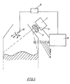
- Le dispositif nécessaire à la mise en oeuvre du procédé suivant l'invention comprend notamment une unité (1) de détection de l'énergie de radiation, dotée soit d'une multitude de capteurs individuels, soit d'un système monodétecteur à balayage opto-mécanique, laquelle unité (1) est protégée par une vanne (2) d'isolation. L'unité (1) est disposée à l'extérieur de la paroi de la voûte du four de manière à scruter la surface totale supérieure de la charge. Entre l'unité (1) de détection et la vanne (2) se trouve un module (3) qui comporte les filtres énergétiques spécifiques pour l'élimination des domaines spectraux propres au C02, au CO, au H2 et au CH4. L'unité (1) de détection est reliée à une unité (5) de traitement des signaux captés qui enregistre également les résultats de mesure quilui parviennent de la part de dispositifs de mesure respectivement du niveau géométrique (6) de la charge, de l'émissivité (7) de la charge, de la température (8) de la charge et du degré d'émission de poussières (9).
- Ainsi la mesure du niveau géométrique (6) de la charge peut être effectuée par un dispositif classique de détermination de niveau dans une enceinte close, tel que le déposant l'a décrit p.ex. dans sa demande de brevet LU 82830. L'émissivité (7) peut être enregistrée par une quelconque unité de mesure de l'intensité énergétique, comme p.ex. par une unité semblable à l'unité (1), qui fait partie de l'installation suivant l'invention.
- Il est évident que l'émissivité de la charge elle-même se situe sur une plage spectrale différente de celle où se situent les rayonnements des gaz. La plage en question doit être suffisamment large pour englober les domaines spectraux propres aux diverses matières enfournées.
- Pour la mesure de la température (8), on utilisera de préférence un pyromètre à tête balayeuse, donc également un instrument classique et on surveillera l'émission de poussières (9) à l'aide d'un néphélémètre approprié ou encore par une simple caméra vidéo.
- L'unité (5) de traitement des signaux est évidemment un ordinateur doté des programmes nécessaires pour effectuer les différentes conversions et les calculs des concentrations individuelles locales en gaz spécifiques et pour fournir sur un écran de visualisation des images compréhensives montrant la distribution de n'importe lequel des composés gazeux au-dessus de l'aire de la charge, respectivement la distribution du pouvoir réducteur.
- D'autres caractéristiques et avantages ressortiront de la descriprions de dessin schématique qui représente de manière non-limitative une forme d'exécution possible du dispositif suivant l'invention.
- On distingue l'unité (1) de détection qui est fixée à l'extérieur de la paroi de la voûte du four et qui est protégé par une vanne (2) d'isolation. Entre la vanne (2) et l'unité (1) se trouve un module de filtration (3), manuel ou automatique, à l'aide duquel on peut intercaler entre la caméra (1) et la source de rayonnement, des filtres absorbant dans le domaine spectrale, soit du C02, soit du CO, soit du CH4, soit encore du H2. Il s'agit de préférence de filtres passe-bande à limite assez étroite.
- La caméra (1) est reliée à l'unité (5) de traitement des signaux captés, un ordinateur qui se charge des différentes conversions et qui reçoit à ces fin les signaux issus des instruments ancillaires de mesure du niveau ou du profil géométrique (6) de la charge, de l'émission de son intensité énergétique (7), de sa température (8) et du degré d'émission des poussières (9).
- Les modes de conversion, des calculs de correction etc. sont aléatoires dans le sens qu'ils dépendent des commodités offertes par l'instrumentation mise en oeuvre, ainsi que des modes de travail préférés par les analystes.
- On peut aussi prévoir, suivant une forme d'exécution particulièrement avantageuse, une unité (11) de régulation qui reçoit ses directives de la part de l'ordinateur (5) central. Cette unité (11) est reliée à une installation (12) de distribution qui peut tourner autour de son axe, respectivement pivoter, si bien que l'on peut à l'aide du distributeur (12) répartir les matières à enfourner sur des plages déterminées au sommet de la charge.
- Ainsi l'ordinateur (5) peut fournir les consignes nécessaires pour procéder à l'aide du distributeur (12) à la répartition judicieuse des matières suivant leur degré de réductibilité et contribuer à la bonne marche du four.
Claims (9)
Applications Claiming Priority (2)
| Application Number | Priority Date | Filing Date | Title |
|---|---|---|---|
| LU83035A LU83035A1 (fr) | 1980-12-24 | 1980-12-24 | Procede et dispositif pour la determination locale du pouvoir reducteur des gaz degages au niveau superieur de la charge de fours industriels |
| LU83035 | 1980-12-24 |
Publications (2)
| Publication Number | Publication Date |
|---|---|
| EP0055204A1 EP0055204A1 (fr) | 1982-06-30 |
| EP0055204B1 true EP0055204B1 (fr) | 1985-01-23 |
Family
ID=19729550
Family Applications (1)
| Application Number | Title | Priority Date | Filing Date |
|---|---|---|---|
| EP81630075A Expired EP0055204B1 (fr) | 1980-12-24 | 1981-11-16 | Procédé et dispositif pour la détermination locale du pouvoir réducteur des gaz dégagés au niveau supérieur de la charge de fours industriels |
Country Status (7)
| Country | Link |
|---|---|
| US (1) | US4434368A (fr) |
| EP (1) | EP0055204B1 (fr) |
| JP (1) | JPS57133338A (fr) |
| AU (1) | AU7882881A (fr) |
| CA (1) | CA1185657A (fr) |
| DE (1) | DE3168541D1 (fr) |
| LU (1) | LU83035A1 (fr) |
Families Citing this family (3)
| Publication number | Priority date | Publication date | Assignee | Title |
|---|---|---|---|---|
| IL190757A (en) * | 2008-04-09 | 2013-03-24 | Rafael Advanced Defense Sys | Method for remote spectral analysis of gas plumes |
| US8052920B2 (en) * | 2009-04-28 | 2011-11-08 | China Steel Corporation | Apparatus for observing interior of a blast furnace system |
| CN112389977A (zh) * | 2020-11-04 | 2021-02-23 | 马鞍山钢铁股份有限公司 | 一种高炉槽下自动看料装置及看料方法 |
Family Cites Families (13)
| Publication number | Priority date | Publication date | Assignee | Title |
|---|---|---|---|---|
| FR1195029A (fr) * | 1957-04-24 | 1959-11-13 | Deutsche Edelstahlwerke Ag | Procédé et dispositif pour l'analyse de masses en fusion, notamment d'acier, à l'intérieur même des fours de fusion |
| FR1239816A (fr) * | 1959-02-09 | 1960-08-26 | Cockerill Ougree Sa | Procédé de mesure de la température d'un corps au moyen d'un pyromètre à radiation |
| FR1302668A (fr) * | 1961-08-03 | 1962-08-31 | Procédé d'analyse et de contrôle des flammes et des systèmes plasmatiques | |
| DE1533829B1 (de) * | 1967-02-06 | 1971-08-05 | Dango & Dienenthal Kg | Sonde zur gas und moellerprobenentnahme und oder temperatur sowie gasdruckmessung bei schachtoefen insbesondere hoch oefen |
| FR1537314A (fr) * | 1967-09-11 | 1968-08-23 | Centre Nat Rech Metall | Procédé pour contrôler le fonctionnement d'un four à cuve |
| SE334485B (fr) * | 1968-04-11 | 1971-04-26 | Aga Ab | |
| JPS4823762B1 (fr) | 1968-08-08 | 1973-07-16 | ||
| LU74579A1 (fr) | 1976-03-17 | 1976-09-01 | ||
| BE841671A (fr) * | 1976-05-10 | 1976-09-01 | Procede d'observation de la surface d'un corps. | |
| DE2632484A1 (de) * | 1976-07-19 | 1978-01-26 | Innotec Oy | Detektionsmittel fuer temperatur-, mengen-, standorts- und konfigurationssteuerung von werkstoffen in einem prozessofen |
| FR2447967A1 (fr) | 1979-01-31 | 1980-08-29 | Siderurgie Fse Inst Rech | Procede et dispositif de determination en continu du profil des charges dans un haut fourneau |
| LU81158A1 (fr) | 1979-04-13 | 1979-06-19 | Wurth Paul Sa | Dispositif de montage d'une sonde radar pour fours a cuve |
| LU81859A1 (fr) | 1979-11-07 | 1981-06-04 | Arbed | Procede de conditionnement de la scorie au cours de l'affinage d'un bain de metal |
-
1980
- 1980-12-24 LU LU83035A patent/LU83035A1/fr unknown
-
1981
- 1981-11-16 EP EP81630075A patent/EP0055204B1/fr not_active Expired
- 1981-11-16 DE DE8181630075T patent/DE3168541D1/de not_active Expired
- 1981-11-24 CA CA000390749A patent/CA1185657A/fr not_active Expired
- 1981-12-22 US US06/333,260 patent/US4434368A/en not_active Expired - Fee Related
- 1981-12-22 JP JP56207966A patent/JPS57133338A/ja active Pending
- 1981-12-23 AU AU78828/81A patent/AU7882881A/en not_active Abandoned
Also Published As
| Publication number | Publication date |
|---|---|
| JPS57133338A (en) | 1982-08-18 |
| DE3168541D1 (en) | 1985-03-07 |
| US4434368A (en) | 1984-02-28 |
| AU7882881A (en) | 1982-07-01 |
| CA1185657A (fr) | 1985-04-16 |
| LU83035A1 (fr) | 1982-07-07 |
| EP0055204A1 (fr) | 1982-06-30 |
Similar Documents
| Publication | Publication Date | Title |
|---|---|---|
| US5038040A (en) | Soil test apparatus | |
| CN101641586B (zh) | 远程光学气体检测装置 | |
| US7847935B2 (en) | Method and apparatus for gas concentration quantitative analysis | |
| JP2006030032A (ja) | ガス中の不純物定量方法及び装置 | |
| WO2016129033A1 (fr) | Spectrophotomètre à canaux multiples et procédé de traitement de données pour spectrophotomètre à canaux multiples | |
| CA1185657A (fr) | Procede et dispositif pour la determination locale du pouvoir reducteur des gaz degages au niveau superieur de la charge de fours industriels | |
| EP0648330A1 (fr) | Appareil et procedes d'analyse raman | |
| CN120254162B (zh) | 一种基于光谱和火焰成像的生物质燃烧原位测量方法 | |
| USH1925H (en) | Apparatus and method for monitoring steel decarburization by remote flame emission spatial imaging spectroscopy | |
| Sładek et al. | Measurements of surface temperature distributions on coal dust particles | |
| FR2524130A1 (fr) | Procede pour detecter l'etat de fonctionnement de tambours tournants tels que des fours tubulaires tournants, et appareil pour la mesure sans contact de la temperature superficielle de tels tambours | |
| US4730940A (en) | Device for pyrometric temperature measurement | |
| Irie et al. | SKYNET | |
| KR101172012B1 (ko) | 컬러 필터 어레이를 사용하는 분광 분석 장치 | |
| Ruzankina et al. | Raman lidar with for geoecological monitoring | |
| JP7598021B2 (ja) | ダスト発生速度評価装置及びダスト発生速度評価方法 | |
| CN117849065A (zh) | 针对外延硅片近表面缺陷的无损定性检测装置及方法 | |
| JP2012108038A (ja) | 排ガスの分析方法及び排ガスの排出制御方法 | |
| FR2564970A1 (fr) | Dispositif de detection spectroradiometrique de la flamme et des parois d'un four et procede pour sa mise en oeuvre | |
| US4355231A (en) | Remote analysis using thermal radiation | |
| Maeda et al. | Optical sensing technique for in situ determination of gas components at elevated temperature by infrared spectroscopy | |
| Bin et al. | Study on Measurement System of Cement Cooler Clinker's Temperature Field | |
| JP2004271537A (ja) | 溶融スラグの温度計測方法 | |
| JP2001249049A (ja) | 溶融スラグの温度計測方法 | |
| RU56630U1 (ru) | Лазерно-искровой спектрометр |
Legal Events
| Date | Code | Title | Description |
|---|---|---|---|
| PUAI | Public reference made under article 153(3) epc to a published international application that has entered the european phase |
Free format text: ORIGINAL CODE: 0009012 |
|
| AK | Designated contracting states |
Designated state(s): BE CH DE FR GB IT NL SE |
|
| 17P | Request for examination filed |
Effective date: 19821119 |
|
| GRAA | (expected) grant |
Free format text: ORIGINAL CODE: 0009210 |
|
| AK | Designated contracting states |
Designated state(s): BE CH DE FR GB IT LI NL SE |
|
| PG25 | Lapsed in a contracting state [announced via postgrant information from national office to epo] |
Ref country code: SE Effective date: 19850123 Ref country code: NL Effective date: 19850123 Ref country code: IT Free format text: LAPSE BECAUSE OF FAILURE TO SUBMIT A TRANSLATION OF THE DESCRIPTION OR TO PAY THE FEE WITHIN THE PRESCRIBED TIME-LIMIT;WARNING: LAPSES OF ITALIAN PATENTS WITH EFFECTIVE DATE BEFORE 2007 MAY HAVE OCCURRED AT ANY TIME BEFORE 2007. THE CORRECT EFFECTIVE DATE MAY BE DIFFERENT FROM THE ONE RECORDED. Effective date: 19850123 |
|
| REF | Corresponds to: |
Ref document number: 3168541 Country of ref document: DE Date of ref document: 19850307 |
|
| NLV1 | Nl: lapsed or annulled due to failure to fulfill the requirements of art. 29p and 29m of the patents act | ||
| PLBE | No opposition filed within time limit |
Free format text: ORIGINAL CODE: 0009261 |
|
| STAA | Information on the status of an ep patent application or granted ep patent |
Free format text: STATUS: NO OPPOSITION FILED WITHIN TIME LIMIT |
|
| 26N | No opposition filed | ||
| PG25 | Lapsed in a contracting state [announced via postgrant information from national office to epo] |
Ref country code: LI Effective date: 19881130 Ref country code: CH Effective date: 19881130 |
|
| PGFP | Annual fee paid to national office [announced via postgrant information from national office to epo] |
Ref country code: DE Payment date: 19881230 Year of fee payment: 8 |
|
| REG | Reference to a national code |
Ref country code: CH Ref legal event code: PL |
|
| PG25 | Lapsed in a contracting state [announced via postgrant information from national office to epo] |
Ref country code: GB Effective date: 19891116 |
|
| PG25 | Lapsed in a contracting state [announced via postgrant information from national office to epo] |
Ref country code: BE Effective date: 19891130 |
|
| BERE | Be: lapsed |
Owner name: ARBED S.A. Effective date: 19891130 |
|
| GBPC | Gb: european patent ceased through non-payment of renewal fee | ||
| PG25 | Lapsed in a contracting state [announced via postgrant information from national office to epo] |
Ref country code: FR Effective date: 19900731 |
|
| PG25 | Lapsed in a contracting state [announced via postgrant information from national office to epo] |
Ref country code: DE Effective date: 19900801 |
|
| REG | Reference to a national code |
Ref country code: FR Ref legal event code: ST |