EP0055312A2 - Elément de résistance d'une jauge à essence disposée verticalement et sa structure de support - Google Patents
Elément de résistance d'une jauge à essence disposée verticalement et sa structure de support Download PDFInfo
- Publication number
- EP0055312A2 EP0055312A2 EP80304759A EP80304759A EP0055312A2 EP 0055312 A2 EP0055312 A2 EP 0055312A2 EP 80304759 A EP80304759 A EP 80304759A EP 80304759 A EP80304759 A EP 80304759A EP 0055312 A2 EP0055312 A2 EP 0055312A2
- Authority
- EP
- European Patent Office
- Prior art keywords
- resistance body
- resistance
- base material
- vertically set
- fuel gauge
- Prior art date
- Legal status (The legal status is an assumption and is not a legal conclusion. Google has not performed a legal analysis and makes no representation as to the accuracy of the status listed.)
- Withdrawn
Links
- 239000000446 fuel Substances 0.000 title claims abstract description 70
- 230000008859 change Effects 0.000 claims abstract description 21
- 229910052751 metal Inorganic materials 0.000 claims abstract description 19
- 239000002184 metal Substances 0.000 claims abstract description 19
- 239000000463 material Substances 0.000 claims description 36
- 229910052782 aluminium Inorganic materials 0.000 claims description 15
- XAGFODPZIPBFFR-UHFFFAOYSA-N aluminium Chemical compound [Al] XAGFODPZIPBFFR-UHFFFAOYSA-N 0.000 claims description 15
- XEEYBQQBJWHFJM-UHFFFAOYSA-N Iron Chemical compound [Fe] XEEYBQQBJWHFJM-UHFFFAOYSA-N 0.000 claims description 10
- 230000003647 oxidation Effects 0.000 claims description 6
- 238000007254 oxidation reaction Methods 0.000 claims description 6
- 239000011248 coating agent Substances 0.000 claims description 5
- 238000000576 coating method Methods 0.000 claims description 5
- 238000009434 installation Methods 0.000 claims description 5
- 229910052742 iron Inorganic materials 0.000 claims description 5
- 229910001220 stainless steel Inorganic materials 0.000 claims description 4
- 239000010935 stainless steel Substances 0.000 claims description 4
- 239000011347 resin Substances 0.000 claims description 2
- 229920005989 resin Polymers 0.000 claims description 2
- 239000002828 fuel tank Substances 0.000 abstract description 10
- 238000007796 conventional method Methods 0.000 description 4
- 238000005260 corrosion Methods 0.000 description 4
- 230000007797 corrosion Effects 0.000 description 4
- 230000003014 reinforcing effect Effects 0.000 description 4
- 238000006073 displacement reaction Methods 0.000 description 3
- 238000004891 communication Methods 0.000 description 2
- 238000005530 etching Methods 0.000 description 2
- 150000007524 organic acids Chemical class 0.000 description 2
- 235000005985 organic acids Nutrition 0.000 description 2
- 239000005011 phenolic resin Substances 0.000 description 2
- XLYOFNOQVPJJNP-UHFFFAOYSA-N water Substances O XLYOFNOQVPJJNP-UHFFFAOYSA-N 0.000 description 2
- 230000009471 action Effects 0.000 description 1
- 230000000772 anti-erosive effect Effects 0.000 description 1
- 239000011230 binding agent Substances 0.000 description 1
- 238000006243 chemical reaction Methods 0.000 description 1
- 238000010276 construction Methods 0.000 description 1
- 238000013016 damping Methods 0.000 description 1
- 230000002708 enhancing effect Effects 0.000 description 1
- 239000011888 foil Substances 0.000 description 1
- 239000003502 gasoline Substances 0.000 description 1
- 230000001771 impaired effect Effects 0.000 description 1
- 238000003780 insertion Methods 0.000 description 1
- 230000037431 insertion Effects 0.000 description 1
- 238000009413 insulation Methods 0.000 description 1
- 238000004519 manufacturing process Methods 0.000 description 1
- 238000005259 measurement Methods 0.000 description 1
- 238000012986 modification Methods 0.000 description 1
- 230000004048 modification Effects 0.000 description 1
- 230000001502 supplementing effect Effects 0.000 description 1
Images

Classifications
-
- G—PHYSICS
- G01—MEASURING; TESTING
- G01F—MEASURING VOLUME, VOLUME FLOW, MASS FLOW OR LIQUID LEVEL; METERING BY VOLUME
- G01F23/00—Indicating or measuring liquid level or level of fluent solid material, e.g. indicating in terms of volume or indicating by means of an alarm
- G01F23/30—Indicating or measuring liquid level or level of fluent solid material, e.g. indicating in terms of volume or indicating by means of an alarm by floats
- G01F23/64—Indicating or measuring liquid level or level of fluent solid material, e.g. indicating in terms of volume or indicating by means of an alarm by floats of the free float type without mechanical transmission elements
- G01F23/68—Indicating or measuring liquid level or level of fluent solid material, e.g. indicating in terms of volume or indicating by means of an alarm by floats of the free float type without mechanical transmission elements using electrically actuated indicating means
Definitions
- This invention relates to a fuel gauge for use in vehicles and more particularly, to a resistance body of a vertically set fuel gauge and a support structure thereof.
- the conventional method consists mainly in using a float adapted to move up and down according to a change in the height of fuel surface, converting the displacement of the float to a circular motion of an electric contact point at the end of an arm connected to the float,, taking out the change in the height of fuel surface as an electric signal of said contact point sliding in a coil resistance body, thereby permitting said electric signal to indicate the remaining amount of fuel by means of a bimetal or coil-type receiver unit.
- such conventional method has several drawbacks such as an unsatisfactory accuracy of the coil resistance body itself, a short range of sliding movement, low degree of absolute accuracy for the displacement of fuel surface. Moreover, since the float is connected to one end of said arm, an ample spacing is required for installation of the fuel gauge, and when the fuel tank is of a transformed shape, there occurs no linear change in resistance value for the remaining amount of fuel.
- the structure of such a vertically set fuel gauge consists of an upper lid attached to a fuel tank, a fuel suction pipe either or not piercing the lid for communication with the inside of the fuel tank, a metal for installing a terminal and a resistance body in a direction vertical to fuel ; . surface in the fuel tank.
- the resistance body is formed of an aluminum base plate having its surface treated by anodic oxidation or a base plate of paper impregnated with phenol resin having a conductive metal foil of high specific resistance applied either to,one surface or both surfaces thereof, thus forming a suitable resistance pattern by etching.
- this resistance body Around this resistance body are provided a float adapted to move up and down following a change in the height.of fuel surface, a contact member attached to the float and adapted to contact the resistance body for detecting a change in resistance value, an external casing designed to protect said elements and formed with orifices for damping a sudden change in the height of fuel surface and a bottom plate for holding at least the lower end of the resistance body of the structural members of the fuel gauge at the bottom of the external casing.
- an electric signal as a change in resistance value is transmitted to a direct read-out meter or differential coil-type meter to indicate the amount of fuel in an analog or manual manner, and said electric signal is treated by A-D conversion to indicate the amount of fuel in a digital manner.
- the resistance body is easily formed with a resistance pattern by etching or similar treatment whereby it is rendered possible to'enhance absolute accuracy of the resistance pattern in a simple manner and to make the resistance pattern conform to a transformed shape of the fuel tank, thus ensuring a linear 'relationship between the amount of fuel and resistance pattern and moreover, since the resistance body can be provided in slender form, it is easy to enhance a decomposed function of change in the height of fuel surface and besides, owing to the action of orifices of the external casing, it is also possible to prevent an abrupt change in the height of fuel surface which may arise from swinging movement of the vehicle. Consequently, it is possible to apply a system of high accuracy to an indication meter, which is characteristic of vertically arranged fuel gauges of this kind.
- this kind of fuel gauge can ensure appreciably high accuracy for indicating fuel amount in the fuel tank, as compared with the conventional method but there still remains the following problem as shown in Fig. 1 of the accompanying drawings, namely, the resistance body 1 is provided, for example, with a reinforcing plate 2 in the back surface and the lower end of the plate 2 is fixed by means of a metal fitting 4 either at the internal bottom of the external casing 3 or at the other bottom thereof. .
- numeral 5 designates a metal fitting for securing the upper end of the resistance body or .reinforcing plate 2 to the inside-of the upper lid 6
- numeral 7 designates a terminal attached to said upper lid 6 for communication of the resistance body and an outside indicator meter (not shown )
- numerals 8 and 9 designate a float and a contact member respectively.
- the resistance body is arranged vertically in the external casing 3 through the upper lid 6, the arrangements require such operation as screw-fixing of the upper and lower ends of the resistance body 1, metal fittings 4 and 5, rivet-checking or fastening in combination with a number of parts provided in the external casing 3 for purposes of positioning the resistance body so that the assembling operation will become so much complicated thus largely disturbing the efficiency of such operations in all.
- a metal plate of aluminum or the like as the base material for the resistance body 14
- at least one surface thereof is provided with a coating 15 treated by anodic oxidation for insulating purposes and the required pattern 16 is fixed onto the surface of said coating.
- a large size base material is subjected to the aforesaid insulating treatment and a large number of resistance patterns 16 are formed at a time and finally cut to the required shape.
- the aluminum material as the base will be exposed at its lateral cut-off surfaces.
- the resistance body 14 under such condition is incorporated in a vertically set fuel gauge, the lateral'surfaces 17 of the material directly exposed are liable to be eroded by organic acids or water contained in fuel such as gasoline and simultaneously, there occurs the promotion of galvanic corrosion between the resistance pattern 16 and the base material with the result that the resistance pattern or base is impaired rapidly in terms of a factor for losing its reliability.
- One object of the present invention is to provide a resistance body for use in a vertically set fuel gauge and a support structure thereof, quite new and much improved over the prior art by eliminating all aforesaid problems and drawbacks involved in the conventional fuel measurement as explained hereinbefore.
- the.present invention which relates to a vertically set fuel gauge wherein there are provided a float movable up and down following a change in the height of fuel surface in a fuel tank and a contact member attached to said float for detecting a change in the height of fuel surface as an electric signal of resistance change while the contact member is held in contact with the resistance.
- a resistance body of a vertically set fuel gauge which is characterized by the fact'that the base material of the resistance body is formed of a metal plate which can become insulated by an insulating treatment.
- said resistance body consists of an aluminum plate having one surface thereof treated by anodic oxidation to become insulated, said insulation treated surface being formed with a resistance circuit pattern necessary for detecting a change in the height of fuel surface.
- this type of resistance body it is also possible to provide insulating layers on both surfaces of an aluminum plate as a base material and to form said resistance circuit pattern on one of said insulating layers and an earth circuit pattern on the other surface respectively. From the viepoint of improving - the durability of said resistance . body, it is desirable to coat both lateral surfaces of said aluminum plate with an insulating protection film.
- a structure of resistance body using a stainless steel plate or iron plate as the base material for the resistance body, in order to ensure mechanical strength of the resistance body, at a satisfactory level, thereby forming the required circuit pattern on one surface thereof after insulating treatment and utilizing the other surface thereof for an earth circuit as it is. Since this type of resistance body ensures high mechanical strength by itself, it becomes possible to make its thickness preferably small so that said possibility will contribute very much to compactness of a vertically set fuel gauge.
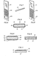
- the resistance body 10 is formed of a metal base such as an aluminum plate, stainless steel plate or iron plate, and after the metal base is subjected to a surface-insulating treatment, the required resistance pattern is provided on said insulated surface thereby simplifying the parts of said resistance body 10 itself on one hand, and on the other hand, the lower end of said resistance body 10 is caused to project outwardly from the bottom integral with the external casing 3 or from a bottom separately formed, and then said projecting portion is supported at the bottom 11 of the external casing, for example, by means of a plate spring 12.
- like numerals in Fig. 1 designate like parts of the same structure in Fig. 3.
- the plate spring 12 is secured to the bottom 11 of the external casing while inserting it in the hole 10B formed in the lower end of the resistance body 10, thus finishing the fixing and assembling operation of the resistance body in a simple manner.
- the resistance pattern 10A for attachment to the resistance body 10 up to its portion corresponding to the position of the bottom 11 of the external casing.
- the angular hole 10B for insertion of the plate spring 12 can be previously formed so as to be positioned at the end portion of the resistance body.
- a round hole 10C may be formed at the lower end of the resistance body, as shown in Fig. 6 and Fig.
- the resistance body 10 can be secured to the bottom of the external casing by means of a pin 13 for engagement with said round hole 10C.
- both said means serve to fix the resistance body 10 by an almost one-touch operation, the labor of assembling the fuel gauge may be reduced to a large extent.
- the resistance body 10 of sufficient strength is secured in place in such a manner as its lower end is pulled outwardly from outside the bottom of the external casing so that backlash of the resistance body 10 after the assembling operation or its loosening tendency due to outer vibrations can be eliminated satisfactorily, thereby contributing very much to improvements in measuring accuracy.
- the assembling operation of the resistance body in a vertically set fuel gauge can be carried out at the same time with other parts so that the present invention is well suited to improvements in the assembling operation as well as to enhancement of accuracy to a large extent along with the small number of parts for use in the fuel gauge, this ensuring extremely high practicability.
- a metal base 18 such as an aluminum plate
- like numerals in Fig. 8 designate like parts in Fig. 2.
- numeral 18 indicates a metal base such as an aluminum plate
- numeral 19 a pattern as an earth circuit as it is in the back surface of the resistance body.
- a protection film 20 to be formed at both lateral surfaces of the resistance body can be formed of a base treated by anodic oxidation in cases where a film of resin is intended or an aluminum plate is used as a base material. Consequently, the metal base 18 is perfectly insulated and coated with an oxidized insulating film 15 and the protection film 20 formed at the lateral surfaces over the whole circumference so that it becomes possible to prevent the corrosion of the metal base due to organic acids or water in fuel and the occurrence of galvanic corrosion, thus enhancing the reliability of the resistance body over long periods of time in use.
- the resistance body of this preferred embodiment when it is formed of a base material such as an aluminum plate of mechanically high strength, not only the surface of the base material but also, especially, its lateral surfaces can be covered with an insulating protection film so that it becomes possible to enhance the durability of the resistance body remarkably thereby further improving the reliability of the vertically set fuel gauge itself.
- the resistance body for detecting the displacement of fuel surface as an electric signal of a change in resistance value is to be formed of the base material of aluminum plate as shown in Figs. 2 and 9, a film 15 treated by anodic oxidation is formed on both surfaces of said base material and the resistance pattern 16 is attached to one surface thereof and an earth circuit 19 is attached to the other surface.
- aluminum material of no sufficient mechanical.strength the necessity of.coating exposed lateral surfaces 17 with an insulating protection film from the viepoint of preventing corrosion of the resistance body and an electric contact and the necessity of applying the required patterns 16 and 19 to both surfaces of the base material 18 individually.
- a suitable reinforcing metal plate 22 is applied to the back surface of the resistance body with a view to supplementing its strength so that said plate 22 can serve as an earth circuit surface.
- a float and a contact member are difficult to constitute.
- a base material 23 consisting of a stainless steel plate or iron plate of mechanically strength, and an insulating layer 24 is formed on one surface of said base material and the required resistance pattern is applied thereto through a binder 25 and then the other surface of the base material 23 is adapted to serve as an earth circuit surface 27 directly.
- the base material 23 is formed of a stainless steet plate, its surface corresponding to the earth circuit surface 27 has only to be finished like a mirror surface. If an iron plate is used in place of a stainless steet plate, its surface has only to be plated with chrominum of anti-erosive and wear-resisting properties.
Landscapes
- Physics & Mathematics (AREA)
- Fluid Mechanics (AREA)
- General Physics & Mathematics (AREA)
- Level Indicators Using A Float (AREA)
- Measurement Of Levels Of Liquids Or Fluent Solid Materials (AREA)
- Cooling, Air Intake And Gas Exhaust, And Fuel Tank Arrangements In Propulsion Units (AREA)
Priority Applications (1)
| Application Number | Priority Date | Filing Date | Title |
|---|---|---|---|
| EP80304759A EP0055312A3 (fr) | 1980-12-30 | 1980-12-30 | Elément de résistance d'une jauge à essence disposée verticalement et sa structure de support |
Applications Claiming Priority (1)
| Application Number | Priority Date | Filing Date | Title |
|---|---|---|---|
| EP80304759A EP0055312A3 (fr) | 1980-12-30 | 1980-12-30 | Elément de résistance d'une jauge à essence disposée verticalement et sa structure de support |
Publications (2)
| Publication Number | Publication Date |
|---|---|
| EP0055312A2 true EP0055312A2 (fr) | 1982-07-07 |
| EP0055312A3 EP0055312A3 (fr) | 1983-05-18 |
Family
ID=8187345
Family Applications (1)
| Application Number | Title | Priority Date | Filing Date |
|---|---|---|---|
| EP80304759A Withdrawn EP0055312A3 (fr) | 1980-12-30 | 1980-12-30 | Elément de résistance d'une jauge à essence disposée verticalement et sa structure de support |
Country Status (1)
| Country | Link |
|---|---|
| EP (1) | EP0055312A3 (fr) |
Cited By (12)
| Publication number | Priority date | Publication date | Assignee | Title |
|---|---|---|---|---|
| FR2503861A1 (fr) * | 1981-04-08 | 1982-10-15 | Jaeger Iberica | Perfectionnements au dispositif emetteur d'un signal electrique et de niveau de liquide dans des reservoirs de combustible |
| FR2534375A1 (fr) * | 1982-10-08 | 1984-04-13 | Jaeger Iberica | Dispositif emetteur d'un signal electrique correspondant a un niveau de liquide |
| FR2538544A1 (fr) * | 1982-12-24 | 1984-06-29 | Jaeger | Capteur de niveau tubulaire pour vehicule automobile |
| EP0168211A1 (fr) * | 1984-07-06 | 1986-01-15 | Ing. C. Olivetti & C., S.p.A. | Dispositif pour détecter le niveau d'un liquide dans un réservoir |
| EP0179220A1 (fr) * | 1984-10-25 | 1986-04-30 | VDO Adolf Schindling AG | Appareil pour mesurer le niveau d'un liquide dans un réservoir |
| FR2632415A1 (fr) * | 1988-06-03 | 1989-12-08 | Jaeger | Capteur potentiometrique de position |
| US4920798A (en) * | 1988-11-17 | 1990-05-01 | Stewart Warner Instrument Corporation | Liquid level sender with linear float |
| US5524487A (en) * | 1994-04-19 | 1996-06-11 | Liu; Paul | Level measuring device with an armless float |
| ES2101618A1 (es) * | 1994-03-01 | 1997-07-01 | Selles Leo Leonelli | Aforador perfeccionado. |
| US8640918B2 (en) | 2004-03-31 | 2014-02-04 | Ch&I Technologies, Inc. | Refillable material transfer system |
| US8684238B2 (en) | 2008-04-21 | 2014-04-01 | C.H.&I. Technologies, Inc. | Aerosol refill cartridge |
| US10221059B2 (en) | 2004-03-31 | 2019-03-05 | Ch&I Technologies, Inc. | Refillable material transfer system |
Family Cites Families (7)
| Publication number | Priority date | Publication date | Assignee | Title |
|---|---|---|---|---|
| CH248945A (de) * | 1943-09-29 | 1947-05-31 | Philips Nv | Elektrischer Widerstand, bei dem eine Widerstandsschicht auf einen Metallträger aufgebracht ist. |
| GB876978A (en) * | 1959-06-30 | 1961-09-06 | Lucas Industries Ltd | Rheostats |
| US3246518A (en) * | 1961-12-13 | 1966-04-19 | Liquid Levels Lectronics Inc | Tank gauge system and level responsive device therefor |
| US3113282A (en) * | 1962-10-16 | 1963-12-03 | Gen Motors Corp | Plastic housed level indicator sending units |
| DE1548903B1 (de) * | 1965-12-02 | 1970-05-06 | Bertram Fab Ernst & Wilhelm | Geraet zum Messen einer in einem Behaelter befindlichen Fluessigkeit |
| US3601744A (en) * | 1969-07-14 | 1971-08-24 | Vishay Intertechnology Inc | Variable resistor with strain-reducing attachment means for the substrate |
| FR2257898A1 (en) * | 1974-01-10 | 1975-08-08 | Monteux Et Cie Maurice | Float type fuel gauge for a vehicle - has float guided by vert. shaft and moving over rheostat coil |
-
1980
- 1980-12-30 EP EP80304759A patent/EP0055312A3/fr not_active Withdrawn
Cited By (15)
| Publication number | Priority date | Publication date | Assignee | Title |
|---|---|---|---|---|
| FR2503861A1 (fr) * | 1981-04-08 | 1982-10-15 | Jaeger Iberica | Perfectionnements au dispositif emetteur d'un signal electrique et de niveau de liquide dans des reservoirs de combustible |
| FR2534375A1 (fr) * | 1982-10-08 | 1984-04-13 | Jaeger Iberica | Dispositif emetteur d'un signal electrique correspondant a un niveau de liquide |
| FR2538544A1 (fr) * | 1982-12-24 | 1984-06-29 | Jaeger | Capteur de niveau tubulaire pour vehicule automobile |
| GB2133887A (en) * | 1982-12-24 | 1984-08-01 | Jaeger | Liquid level probe |
| US4702107A (en) * | 1984-07-06 | 1987-10-27 | Ing. C. Olivetti & C., S.P.A. | Device for detecting the level of a liquid contained in a tank |
| EP0168211A1 (fr) * | 1984-07-06 | 1986-01-15 | Ing. C. Olivetti & C., S.p.A. | Dispositif pour détecter le niveau d'un liquide dans un réservoir |
| EP0179220A1 (fr) * | 1984-10-25 | 1986-04-30 | VDO Adolf Schindling AG | Appareil pour mesurer le niveau d'un liquide dans un réservoir |
| FR2632415A1 (fr) * | 1988-06-03 | 1989-12-08 | Jaeger | Capteur potentiometrique de position |
| US4920798A (en) * | 1988-11-17 | 1990-05-01 | Stewart Warner Instrument Corporation | Liquid level sender with linear float |
| EP0369260A3 (fr) * | 1988-11-17 | 1991-02-20 | Stewart Warner Corporation | Transmetteur de niveau de liquide à flotteur linéaire |
| ES2101618A1 (es) * | 1994-03-01 | 1997-07-01 | Selles Leo Leonelli | Aforador perfeccionado. |
| US5524487A (en) * | 1994-04-19 | 1996-06-11 | Liu; Paul | Level measuring device with an armless float |
| US8640918B2 (en) | 2004-03-31 | 2014-02-04 | Ch&I Technologies, Inc. | Refillable material transfer system |
| US10221059B2 (en) | 2004-03-31 | 2019-03-05 | Ch&I Technologies, Inc. | Refillable material transfer system |
| US8684238B2 (en) | 2008-04-21 | 2014-04-01 | C.H.&I. Technologies, Inc. | Aerosol refill cartridge |
Also Published As
| Publication number | Publication date |
|---|---|
| EP0055312A3 (fr) | 1983-05-18 |
Similar Documents
| Publication | Publication Date | Title |
|---|---|---|
| US20040221647A1 (en) | Liquid level sending unit with flexible sensor board | |
| US7530269B2 (en) | Fuel level sensor | |
| US6389892B1 (en) | Liquid level detection device and method of manufacturing conductor electrode used therefor | |
| JP5152679B2 (ja) | 液面検出装置 | |
| US4827769A (en) | Fuel level sensor with buried conductor | |
| US4920798A (en) | Liquid level sender with linear float | |
| US6851315B2 (en) | Hermetic fuel level sender | |
| US20100269586A1 (en) | Sensor for inductive measure of fluid level | |
| EP0409458B1 (fr) | Palpeur de niveau d'un fluide à ultrasons | |
| GB2157001A (en) | Weighing machine | |
| US5021737A (en) | Proximity sensor resistant to axial and torsional forces | |
| KR20120102632A (ko) | 액면 검출 장치 | |
| US4227410A (en) | Attitude compensating indicator | |
| EP0038894A2 (fr) | Dispositif de mesure de niveau de combustible liquide | |
| US4358956A (en) | Liquid level indicator | |
| JPH0110897Y2 (fr) | ||
| US4744247A (en) | Device for electrical measurement of the level of a liquid in a fuel tank | |
| KR0152593B1 (ko) | 회전 커넥터 | |
| JP2003004508A (ja) | 液面レベルセンサ | |
| JP2003004506A (ja) | 液面レベルセンサ | |
| GB2096862A (en) | Electromagnetic transducer | |
| JPH06147955A (ja) | 静電容量式レベルセンサ | |
| EP0262264A1 (fr) | Instrument indicateur | |
| JPS6331011Y2 (fr) | ||
| GB2086053A (en) | Sensing device |
Legal Events
| Date | Code | Title | Description |
|---|---|---|---|
| PUAI | Public reference made under article 153(3) epc to a published international application that has entered the european phase |
Free format text: ORIGINAL CODE: 0009012 |
|
| AK | Designated contracting states |
Designated state(s): DE FR GB IT SE |
|
| PUAL | Search report despatched |
Free format text: ORIGINAL CODE: 0009013 |
|
| AK | Designated contracting states |
Designated state(s): DE FR GB IT SE |
|
| 17P | Request for examination filed |
Effective date: 19830408 |
|
| STAA | Information on the status of an ep patent application or granted ep patent |
Free format text: STATUS: THE APPLICATION IS DEEMED TO BE WITHDRAWN |
|
| 18D | Application deemed to be withdrawn |
Effective date: 19840927 |
|
| RIN1 | Information on inventor provided before grant (corrected) |
Inventor name: TANAKA, YASUYUKI |