EP0055406A1 - Procédé pour la production d'éléments de prothèses en graphite pyrolytique - Google Patents
Procédé pour la production d'éléments de prothèses en graphite pyrolytique Download PDFInfo
- Publication number
- EP0055406A1 EP0055406A1 EP81110242A EP81110242A EP0055406A1 EP 0055406 A1 EP0055406 A1 EP 0055406A1 EP 81110242 A EP81110242 A EP 81110242A EP 81110242 A EP81110242 A EP 81110242A EP 0055406 A1 EP0055406 A1 EP 0055406A1
- Authority
- EP
- European Patent Office
- Prior art keywords
- pyrocarbon
- substrate
- accordance
- deposition
- making
- Prior art date
- Legal status (The legal status is an assumption and is not a legal conclusion. Google has not performed a legal analysis and makes no representation as to the accuracy of the status listed.)
- Granted
Links
- 238000004519 manufacturing process Methods 0.000 title claims description 9
- 239000000758 substrate Substances 0.000 claims abstract description 65
- OKTJSMMVPCPJKN-UHFFFAOYSA-N Carbon Chemical compound [C] OKTJSMMVPCPJKN-UHFFFAOYSA-N 0.000 claims abstract description 23
- 210000003709 heart valve Anatomy 0.000 claims abstract description 20
- 230000008021 deposition Effects 0.000 claims description 22
- 238000000034 method Methods 0.000 claims description 20
- 239000000463 material Substances 0.000 claims description 18
- ATUOYWHBWRKTHZ-UHFFFAOYSA-N Propane Chemical compound CCC ATUOYWHBWRKTHZ-UHFFFAOYSA-N 0.000 claims description 8
- 239000002245 particle Substances 0.000 claims description 5
- 238000005299 abrasion Methods 0.000 claims description 4
- 239000001294 propane Substances 0.000 claims description 4
- 229910052710 silicon Inorganic materials 0.000 claims description 4
- 239000010703 silicon Substances 0.000 claims description 4
- 229910021383 artificial graphite Inorganic materials 0.000 claims description 3
- 229910052799 carbon Inorganic materials 0.000 claims description 3
- 229930195733 hydrocarbon Natural products 0.000 claims description 3
- 150000002430 hydrocarbons Chemical class 0.000 claims description 3
- 239000004215 Carbon black (E152) Substances 0.000 claims description 2
- 239000003701 inert diluent Substances 0.000 claims description 2
- 238000000354 decomposition reaction Methods 0.000 claims 2
- 238000010438 heat treatment Methods 0.000 claims 2
- 229910002804 graphite Inorganic materials 0.000 abstract description 19
- 239000010439 graphite Substances 0.000 abstract description 19
- 238000003754 machining Methods 0.000 abstract description 19
- 239000011248 coating agent Substances 0.000 abstract description 13
- 238000000576 coating method Methods 0.000 abstract description 13
- 238000005498 polishing Methods 0.000 abstract description 5
- 239000002296 pyrolytic carbon Substances 0.000 description 8
- 230000015572 biosynthetic process Effects 0.000 description 7
- XKRFYHLGVUSROY-UHFFFAOYSA-N Argon Chemical compound [Ar] XKRFYHLGVUSROY-UHFFFAOYSA-N 0.000 description 6
- 239000002131 composite material Substances 0.000 description 6
- 239000007789 gas Substances 0.000 description 5
- 239000000203 mixture Substances 0.000 description 4
- HBMJWWWQQXIZIP-UHFFFAOYSA-N silicon carbide Chemical compound [Si+]#[C-] HBMJWWWQQXIZIP-UHFFFAOYSA-N 0.000 description 4
- 229910010271 silicon carbide Inorganic materials 0.000 description 4
- 229910052786 argon Inorganic materials 0.000 description 3
- 238000001816 cooling Methods 0.000 description 3
- UIIMBOGNXHQVGW-UHFFFAOYSA-M Sodium bicarbonate Chemical compound [Na+].OC([O-])=O UIIMBOGNXHQVGW-UHFFFAOYSA-M 0.000 description 2
- QAOWNCQODCNURD-UHFFFAOYSA-N Sulfuric acid Chemical compound OS(O)(=O)=O QAOWNCQODCNURD-UHFFFAOYSA-N 0.000 description 2
- 238000005275 alloying Methods 0.000 description 2
- 238000005137 deposition process Methods 0.000 description 2
- 210000005069 ears Anatomy 0.000 description 2
- 230000000694 effects Effects 0.000 description 2
- 238000009434 installation Methods 0.000 description 2
- 238000005259 measurement Methods 0.000 description 2
- 238000012544 monitoring process Methods 0.000 description 2
- 230000002093 peripheral effect Effects 0.000 description 2
- 238000000926 separation method Methods 0.000 description 2
- 239000000126 substance Substances 0.000 description 2
- GRYLNZFGIOXLOG-UHFFFAOYSA-N Nitric acid Chemical compound O[N+]([O-])=O GRYLNZFGIOXLOG-UHFFFAOYSA-N 0.000 description 1
- UIIMBOGNXHQVGW-DEQYMQKBSA-M Sodium bicarbonate-14C Chemical compound [Na+].O[14C]([O-])=O UIIMBOGNXHQVGW-DEQYMQKBSA-M 0.000 description 1
- 230000004308 accommodation Effects 0.000 description 1
- 230000002411 adverse Effects 0.000 description 1
- HSFWRNGVRCDJHI-UHFFFAOYSA-N alpha-acetylene Natural products C#C HSFWRNGVRCDJHI-UHFFFAOYSA-N 0.000 description 1
- 235000015241 bacon Nutrition 0.000 description 1
- 239000008280 blood Substances 0.000 description 1
- 210000004369 blood Anatomy 0.000 description 1
- 230000017531 blood circulation Effects 0.000 description 1
- 238000005336 cracking Methods 0.000 description 1
- 230000006378 damage Effects 0.000 description 1
- 230000003247 decreasing effect Effects 0.000 description 1
- 238000013461 design Methods 0.000 description 1
- 229910003460 diamond Inorganic materials 0.000 description 1
- 239000010432 diamond Substances 0.000 description 1
- 239000003085 diluting agent Substances 0.000 description 1
- FCSCTLGIPUOGOC-UHFFFAOYSA-N disilver;oxido-(oxido(dioxo)chromio)oxy-dioxochromium Chemical compound [Ag+].[Ag+].[O-][Cr](=O)(=O)O[Cr]([O-])(=O)=O FCSCTLGIPUOGOC-UHFFFAOYSA-N 0.000 description 1
- 238000004090 dissolution Methods 0.000 description 1
- 230000008030 elimination Effects 0.000 description 1
- 238000003379 elimination reaction Methods 0.000 description 1
- 125000002534 ethynyl group Chemical group [H]C#C* 0.000 description 1
- 230000001747 exhibiting effect Effects 0.000 description 1
- 239000008246 gaseous mixture Substances 0.000 description 1
- 239000001307 helium Substances 0.000 description 1
- 229910052734 helium Inorganic materials 0.000 description 1
- SWQJXJOGLNCZEY-UHFFFAOYSA-N helium atom Chemical compound [He] SWQJXJOGLNCZEY-UHFFFAOYSA-N 0.000 description 1
- 239000007943 implant Substances 0.000 description 1
- 230000013011 mating Effects 0.000 description 1
- 239000005055 methyl trichlorosilane Substances 0.000 description 1
- JLUFWMXJHAVVNN-UHFFFAOYSA-N methyltrichlorosilane Chemical compound C[Si](Cl)(Cl)Cl JLUFWMXJHAVVNN-UHFFFAOYSA-N 0.000 description 1
- 238000012986 modification Methods 0.000 description 1
- 230000004048 modification Effects 0.000 description 1
- 229910017604 nitric acid Inorganic materials 0.000 description 1
- RVTZCBVAJQQJTK-UHFFFAOYSA-N oxygen(2-);zirconium(4+) Chemical compound [O-2].[O-2].[Zr+4] RVTZCBVAJQQJTK-UHFFFAOYSA-N 0.000 description 1
- QQONPFPTGQHPMA-UHFFFAOYSA-N propylene Natural products CC=C QQONPFPTGQHPMA-UHFFFAOYSA-N 0.000 description 1
- 125000004805 propylene group Chemical group [H]C([H])([H])C([H])([*:1])C([H])([H])[*:2] 0.000 description 1
- 238000005488 sandblasting Methods 0.000 description 1
- 238000007493 shaping process Methods 0.000 description 1
- 229910000030 sodium bicarbonate Inorganic materials 0.000 description 1
- 235000017557 sodium bicarbonate Nutrition 0.000 description 1
- 238000011144 upstream manufacturing Methods 0.000 description 1
- 239000011800 void material Substances 0.000 description 1
- 229910001928 zirconium oxide Inorganic materials 0.000 description 1
Images
Classifications
-
- A—HUMAN NECESSITIES
- A61—MEDICAL OR VETERINARY SCIENCE; HYGIENE
- A61F—FILTERS IMPLANTABLE INTO BLOOD VESSELS; PROSTHESES; DEVICES PROVIDING PATENCY TO, OR PREVENTING COLLAPSING OF, TUBULAR STRUCTURES OF THE BODY, e.g. STENTS; ORTHOPAEDIC, NURSING OR CONTRACEPTIVE DEVICES; FOMENTATION; TREATMENT OR PROTECTION OF EYES OR EARS; BANDAGES, DRESSINGS OR ABSORBENT PADS; FIRST-AID KITS
- A61F2/00—Filters implantable into blood vessels; Prostheses, i.e. artificial substitutes or replacements for parts of the body; Appliances for connecting them with the body; Devices providing patency to, or preventing collapsing of, tubular structures of the body, e.g. stents
- A61F2/02—Prostheses implantable into the body
- A61F2/24—Heart valves ; Vascular valves, e.g. venous valves; Heart implants, e.g. passive devices for improving the function of the native valve or the heart muscle; Transmyocardial revascularisation [TMR] devices; Valves implantable in the body
- A61F2/2403—Heart valves ; Vascular valves, e.g. venous valves; Heart implants, e.g. passive devices for improving the function of the native valve or the heart muscle; Transmyocardial revascularisation [TMR] devices; Valves implantable in the body with pivoting rigid closure members
-
- A—HUMAN NECESSITIES
- A61—MEDICAL OR VETERINARY SCIENCE; HYGIENE
- A61F—FILTERS IMPLANTABLE INTO BLOOD VESSELS; PROSTHESES; DEVICES PROVIDING PATENCY TO, OR PREVENTING COLLAPSING OF, TUBULAR STRUCTURES OF THE BODY, e.g. STENTS; ORTHOPAEDIC, NURSING OR CONTRACEPTIVE DEVICES; FOMENTATION; TREATMENT OR PROTECTION OF EYES OR EARS; BANDAGES, DRESSINGS OR ABSORBENT PADS; FIRST-AID KITS
- A61F2/00—Filters implantable into blood vessels; Prostheses, i.e. artificial substitutes or replacements for parts of the body; Appliances for connecting them with the body; Devices providing patency to, or preventing collapsing of, tubular structures of the body, e.g. stents
- A61F2/02—Prostheses implantable into the body
- A61F2/24—Heart valves ; Vascular valves, e.g. venous valves; Heart implants, e.g. passive devices for improving the function of the native valve or the heart muscle; Transmyocardial revascularisation [TMR] devices; Valves implantable in the body
- A61F2/2409—Support rings therefor, e.g. for connecting valves to tissue
-
- A—HUMAN NECESSITIES
- A61—MEDICAL OR VETERINARY SCIENCE; HYGIENE
- A61L—METHODS OR APPARATUS FOR STERILISING MATERIALS OR OBJECTS IN GENERAL; DISINFECTION, STERILISATION OR DEODORISATION OF AIR; CHEMICAL ASPECTS OF BANDAGES, DRESSINGS, ABSORBENT PADS OR SURGICAL ARTICLES; MATERIALS FOR BANDAGES, DRESSINGS, ABSORBENT PADS OR SURGICAL ARTICLES
- A61L27/00—Materials for grafts or prostheses or for coating grafts or prostheses
- A61L27/02—Inorganic materials
- A61L27/08—Carbon ; Graphite
-
- C—CHEMISTRY; METALLURGY
- C04—CEMENTS; CONCRETE; ARTIFICIAL STONE; CERAMICS; REFRACTORIES
- C04B—LIME, MAGNESIA; SLAG; CEMENTS; COMPOSITIONS THEREOF, e.g. MORTARS, CONCRETE OR LIKE BUILDING MATERIALS; ARTIFICIAL STONE; CERAMICS; REFRACTORIES; TREATMENT OF NATURAL STONE
- C04B35/00—Shaped ceramic products characterised by their composition; Ceramics compositions; Processing powders of inorganic compounds preparatory to the manufacturing of ceramic products
- C04B35/515—Shaped ceramic products characterised by their composition; Ceramics compositions; Processing powders of inorganic compounds preparatory to the manufacturing of ceramic products based on non-oxide ceramics
- C04B35/52—Shaped ceramic products characterised by their composition; Ceramics compositions; Processing powders of inorganic compounds preparatory to the manufacturing of ceramic products based on non-oxide ceramics based on carbon, e.g. graphite
-
- A—HUMAN NECESSITIES
- A61—MEDICAL OR VETERINARY SCIENCE; HYGIENE
- A61F—FILTERS IMPLANTABLE INTO BLOOD VESSELS; PROSTHESES; DEVICES PROVIDING PATENCY TO, OR PREVENTING COLLAPSING OF, TUBULAR STRUCTURES OF THE BODY, e.g. STENTS; ORTHOPAEDIC, NURSING OR CONTRACEPTIVE DEVICES; FOMENTATION; TREATMENT OR PROTECTION OF EYES OR EARS; BANDAGES, DRESSINGS OR ABSORBENT PADS; FIRST-AID KITS
- A61F2310/00—Prostheses classified in A61F2/28 or A61F2/30 - A61F2/44 being constructed from or coated with a particular material
- A61F2310/00005—The prosthesis being constructed from a particular material
- A61F2310/00161—Carbon; Graphite
Definitions
- Pyrolytic carbon or pyrocarbon is formed by thermally decomposing gaseous hydrocarbons or other carbon-containing substances in vaporous form so that a substrate in the deposition region becomes coated.
- U.S. Patent No, 3,138,434 shows the formation of a simple anisotropic pyrocarbon article designed for use as a nose cone or the like wherein a mandrel of appropriate shape is coated completely about its exterior surface and subsequently cut in half and separated from the pyrocarbon deposit to create a pair of nose cones. Reentrant angles on the substrate are employed such as to provide for easy separation of the pyrocarbon article from the underlying substrate.
- U.S. Patent No. 3,399,969 teaches the formation of massive deposits of isotropic pyrolytic carbon. In most instances, these pyrocarbon deposits were intended for permanent use as a part of a composite article, and thus the achievement of a strong bond between the pyrocarbon layer and the underlying substrate was considered to be of significant importance.
- isotropic pyrolytic carbon has the further important characteristic of exhibiting excellent wear resistance.
- this important characteristic of pyrocarbon in an implanted prosthetic device might be considered a disadvantage in its fabrication because pyrocarbon is hard and difficult to machine, and prosthetic devices, particularly heart valves, must be machined to close tolerances to assure their continuing to function in the intended manner over the lifetime of the patient.
- heart valves having an annular valve body and one or more relatively moveable valve members have been assembled either by stretching the valve body or compressing the valve members.
- graphite substrates covered with Pyrolite are structurally strong and have reasonable flexibility, occasionally breakage may occur during the assembly process.
- annular valve bodies of substantially totally pyrocarbon thinner yet strong orifice rings are provided which are inherently more flexible and capable of withstanding greater deformation or stretching without breakage during assembly.
- Still another advantage arises from the fact that, when a thin pyrocarbon coating (e.g., 0.006 inch) was earlier employed on a substrate, following its precise machining to create the heart valve component, it was necessary to subject the component to X-ray monitoring in order to determine the precise position of the substrate. This enables a determination to be made whether there is the minimum required pyrocarbon thickness present in the final component at specific locations where potential wear will be the greatest. Clearly, this is no longer a problem when the component is manufactured from all pyrocarbon.
- a thin pyrocarbon coating e.g., 0.006 inch
- Isotropic, artificial graphite sold under the tradename POCO serves as an appropriate removable substrate which is relatively easily machinable as compared to pyrocarbon. Accordingly, depending upon the type of object one wishes to make, the mirror image of the more complicated surface is machined in a piece of POCO graphite of appropriate size. Thereafter, the POCO graphite substrate is loaded into a suitable pyrocarbon coating device wherein a layer of pyrocarbon of the desired thickness is deposited as generally taught in U.S. Patent No. 3,399,969, issued September 3, 1968 to Jack C. Bokros et al.
- a heart valve body By appropriately shaping the substrate, a heart valve body can be produced which will require only a minimum of further machining.
- an annular valve body having a complex interior surface and top and bottom faces can be deposited upon a mirror image substrate so that only the least critical outer face need thereafter be machined.
- the pyrocarbon which is produced is, of course, very important inasmuch as, without a substrate in the resultant object, it is the sole structural member and must produce the durability and strength needed in the object itself. It is known in the art to control the deposition process by selection of-gases, proportion of diluent, selection of temperature, bed size and coating rate, as taught in the aforementioned U.S. patent, to create pyrocarbon having the desired physical characteristics. In this respect, the pyrocarbon deposited should be isotropic in form, having a BAF of not greater than about 1.5, and should have a density of at least 70% of maximum theoretical density.
- the Bacon Anisotropy Factor (BAF) is an accepted measure of preferred orientation of the layer planes in the carbon structure.
- the isotropic pyrolytic carbon may be deposited having a fairly broad range of apparent crystallite sizes; however, it is preferred that the crystallite size be between about 10°A. and about 100°A. Such pyrocarbon will have a hardness of greater than about 200 (DPH-50 gram load).
- alloying of the pyrocarbon with silicon carbide in a minor amount increases the structural strength without decreasing the biocompatibility of the material, and preferably the pyrocarbon is deposited in a manner so as to contain between about 5 and about 20 weight percent silicon, based upon total amount of silicon plus carbon in the material
- pyrocarbon is intended to include pyrolytic carbon containing a minor percentage of silicon carbide or a similar carbide alloying material.
- the deposition process is normally carried out at a temperature between about 1200°C. and 1500°C., although higher temperatures could be employed if desired.
- the deposition is generally carried out using a mixture of an inert diluent, such as helium or argon, and a carbonaceous gas, usually a hydrocarbon.
- a suitable coating atmosphere might be about 30 volume percent propane and 70 volume percent argon.
- propane a mixture of acetylene and propylene might be used instead of propane.
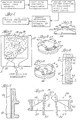
- Coating is carried out in a suitable deposition furnace 11 such as that illustrated in FIGURE 2.
- Articles 13 to be coated are levitated or suspended in an enclosure 15 that is heated by suitable peripheral heater arrangement 17.
- a fluidizing flow of gas is fed in through a supply conduit 19 at the bottom of the furnace and through a multi-apertured diffuser plate 21 to spread the flow of gas uniformly upward throughout the enclosure.
- the substrates or the articles 13 being coated can be suspended by thin wires or the like from an upper region within the furnace so that they are located within the pyrocarbon deposition region.
- the requisite amount of deposition surface area is provided in the pyrocarbon deposition region by an associated bed 23 of small particles, such as zirconium oxide or silicon carbide particles between about 2 to 500 microns in diameter, as also taught in the aforementioned U.S. patent.
- the coating conditions are adjusted so as to achieve a satisfactory rate of deposition, i.e. not greater than about 1000 microns per hour, of pyrocarbon which will have the desired physical characteristics previously mentioned.
- the substrate should have appropriate chemical-and physical characteristics so as to rende'r it compatible with these coating conditions and so as to also be relatively easily removable following the completion of the pyrocarbon deposition step.
- Isotropic artificial graphite is the preferred sustrate material, such as that which is sold under the tradename POCO, and preferably the isotropy of the substrate should measure not greater than about 1.1 BAF.
- the substrate In addition to being stable at the pyrocarbon deposition temperature, the substrate should have a coefficient of thermal expansion(CTE) between about 6 and about 9 x 10 -6° C. Such a CTE will match or slightly exceed that of the pyrocarbon being deposited so that there should be no difficulty with the possibility of cracking the pyrocarbon during cooling of the coated substrate from the relatively high coating temperature to ambient.
- the deposition of pyrocarbon is carried out for a sufficient length of time to build up a deposit of the desired thickness, which should be at least about 1/4 mm. but which will often be greater depending upon the particular object being formed.
- the thickness of the pyrocarbon deposit may typically be in the range from about 3/4mm. to about 1.5mm.
- the excess pyrocarbon which was deposited on the associated surfaces of the substrate may be removed by a rough grinding process leaving a pyrocarbon deposit which resembles that of the ultimate object, and a major portion of the substrate may also be removed, by boring, grinding or the like.
- the portions of the substrate reasonably distant from the interface where the pyrocarbon deposit began are removable by operations which need not be held to close tolerance.
- the remainder of the substrate is removed or eliminated or dissolved using a process that does not chemically or physically affect the pyrocarbon.
- chemical dissolution of POCO graphite may take place using the mixture of hot silver dichromate and sulfuric acid; alternatively, it can be removed electrolytically in a bath of nitric acid without adversely affecting the pyrocarbon.
- the pyrocarbon is deposited under conditions such that it has a hardness greater than about 200 as measured on the diamond pyramid hardness(DPH) scale using a 50-gram load.
- Pyrocarbon of such a hardness will resist abrasion by a suitable grit of substantially lesser hardness (such as sodium bicarbonate or grits of the type used in certain polishing operations which will erode away the remains of the POCO graphite substrate.
- the abrasion process actually exerts some polishing effect upon the pyrocarbon which readies its surface for ultimate use as a part of a prosthetic device.
- the pyrocarbon surface of the object that is opposite that which forms adjacent the machined surface of the substrate is finally fashioned or finish-ground.
- This opposite surface is chosen so that it is a relatively noncritical surface having relatively greater tolerances, e.g. one which may be susceptible to fairly simple semi-automatic grinding.
- the outer surface is preferably chosen to be the opposite surface which generally requires only the formation of a groove for the accommodation of a suturing ring or the like.
- FIGURES 3 and 7 illustrate the different stages which may occur in the formation of an orifice ring or valve body 31 of an artificial heart valve 33 of the type shown in cross-section in FIGURE 8.
- the orifice ring 31 is an annular body having a groove 35 in its outer surface for the acceptance of a suturing ring and having a generally cylindrical inner surface 37 which defines an axial passageway of generally circular cross-section.
- a pair of standards 39 are formed in upstanding relationship to the major portion of the upper surface of the annular body 31, and each standard includes a flat inner face 41 wherein there are formed a pair of depressions 43 which receive correspondingly shaped ears that protrude from opposite sides of a pair of relatively flat leaflets 45.
- the depressions 43 are generally triangular or pie-shaped with the lower vertex defining the eccentric pivot axis of one of the leaflets and the upper arcuate edge guiding the pivoting movement of the leaflets 45 between the open and closed portions.
- the passageway through the valve body 31 below the leaflets is of slightly larger diameter than the passageway above the leaflets (on the upstream side).
- a pair of arcuate seats 49 are formed having a downstream facing curved surface which mates with the.curved edge of the leaflets.
- the interior surface 37 of the valve body 31 requires a fair amount of machining, and in a precision-made device, such as a heart valve for installation in a human patient, very close tolerances must be held. It has been found that, not only can a major portion of the machining of the hard pyrocarbon material be avoided, but a thinner, improved heart valve body can be created by forming the object substantially entirely of pyrocarbon using a method which includes the initial step of appropriately machining the mirror image in a suitable substrate material.
- FIGURE 3 Illustrated in FIGURE 3 is a short generally cylindrical disc 51 having two upstanding appendages 53 that may be employed to form an orifice ring in accordance with this improved method.
- the outer surface of the cylinder 51 will constitute the deposition surface for formation of the interior surface at the orifice ring.
- the flat bottom surface of the orifice ring is machined into the cylinder as a flat flange 55 at the bottom of a groove extending 360° about the surface.
- the top surface is formed by a similar flange 57 which is interrupted in the regions of the two appendages 53 where the standards are to be formed.
- the mirror image of the interior surface 37 of the valve body is also machined in the outer surface of the disc 51 which includes the counterparts 59 of the downstream-facing arcuate ledges 49 serving as the seats for each of the leaflets in the closed position and the flat faces 41.
- the depressions 43 in the flat faces take the form of pie-shaped projections 61 which extend outward from the flat diametrically opposed surfaces.
- This relatively small object of machined POCO graphite which may be about 22 to 25mm. in diameter and about 4 to 5mm. high in'the region other than that of the standards, is coated with pyrocarbon in a suitable coating furnace for a time sufficient to create a deposit of pyrocarbon having an average thickness of about 1mm.
- a deposition temperature of about l400°C. and using a mixture of about 30 percent propane and 70 percent argon, the pyrocarbon deposited will have a density of about 1.8 grams/cm. 3 .
- the pyrocarbon is alloyed with silicon carbide, which increases its strength and hardness, and methyltrichlorosilane may be added to the gaseous mixture to produce such alloyed pyrocarbon having a density of about 2 g/cm 3 and having a hardness just above 250 (DPH-50 gram load).
- methyltrichlorosilane may be added to the gaseous mixture to produce such alloyed pyrocarbon having a density of about 2 g/cm 3 and having a hardness just above 250 (DPH-50 gram load).
- the presence of the bed of small particles assures an isotropy of not greater than 1.1 BAF.
- a coating rate of about 5 microns per minute is achieved so that the total time of deposition may be about 200 minutes.
- the pyrocarbon-coated substrate may have the general appearance shown in FIGURE 4 with the outer surface being completely enveloped in dense pyrocarbon.
- the center of the substrate can be bored out leaving a thin layer 65, i.e. about a millimeter thick of the graphite substrate interior of the diametrically opposed flat surfaces of the standards as illustrated in FIGURES 5 and 6.
- the pyrocarbon'and graphite lying more than one-quarter millimeter below the bottom surface can be removed, as by grinding to about the line x-x in FIGURE 6.
- the region above the upper surface and also above the standards (as indicated by line y-y) can also be removed.
- the composite object as illustrated in FIGURE 5, has a natural configuration in its outer surface, generally as a result.of the location of top and bottom flanges 57,55, of a peripheral groove in the region where the groove 35 of the suture ring is desired, thus minimizing the amount of machining necessary to finish the.groove.
- the remainder of the graphite substrate is removed by transferring the object to a device for the sand-blasting or abrading of objects, using a suitable grit such as sodium bicarbonate, which has a hardness substantially less than the hardness of the pyrocarbon.
- a suitable grit such as sodium bicarbonate, which has a hardness substantially less than the hardness of the pyrocarbon.
- the removal of the remainder of the original graphite substrate by the grit also effects a prepolishing of the surfaces upon which the pyrocarbon was deposited, and the complex interior surface and the upper and lower surfaces of the valve body 31 are essentially ready for a finish polishing operation.
- Minimal machining is necessary along the circumference of the upper and lower edges of the orifice-ring and in the region of the groove for the suture ring, and upon its completion and finish polishing, the fabrication of the orifice ring 31 is complete.
- the resultant all-pyrocarbon orifice ring 31 is substantially thinner in profile than one made from a composite of a substrate plus pyrocarbon, and accordingly a slightly larger central flow passageway is provided in a heart valve 33 of a given exterior diameter which reduces the overall resistance to the flow of blood therethrough.
- the all-pyrocarbon nature provides elasticity greater than that of a composite object and thus allows for easier installation of the leaflets 45'into the depressions 43 in the standards, and it also permits greater flexibility of design of mating components in prosthetic devices in general. It of course eliminates substantially all of the precision grinding of pyrocarbon and obviates the need for X-ray monitoring to assure minimum pyrocarbon thicknesses are present at certain locations on 'the orifice ring.
Landscapes
- Health & Medical Sciences (AREA)
- Engineering & Computer Science (AREA)
- Chemical & Material Sciences (AREA)
- Cardiology (AREA)
- Veterinary Medicine (AREA)
- Oral & Maxillofacial Surgery (AREA)
- Transplantation (AREA)
- Life Sciences & Earth Sciences (AREA)
- Animal Behavior & Ethology (AREA)
- General Health & Medical Sciences (AREA)
- Public Health (AREA)
- Biomedical Technology (AREA)
- Ceramic Engineering (AREA)
- Vascular Medicine (AREA)
- Heart & Thoracic Surgery (AREA)
- Inorganic Chemistry (AREA)
- Dermatology (AREA)
- Medicinal Chemistry (AREA)
- Manufacturing & Machinery (AREA)
- Epidemiology (AREA)
- Materials Engineering (AREA)
- Structural Engineering (AREA)
- Organic Chemistry (AREA)
- Prostheses (AREA)
- Carbon And Carbon Compounds (AREA)
- External Artificial Organs (AREA)
- Materials For Medical Uses (AREA)
Applications Claiming Priority (2)
| Application Number | Priority Date | Filing Date | Title |
|---|---|---|---|
| US22068180A | 1980-12-29 | 1980-12-29 | |
| US220681 | 1980-12-29 |
Publications (2)
| Publication Number | Publication Date |
|---|---|
| EP0055406A1 true EP0055406A1 (fr) | 1982-07-07 |
| EP0055406B1 EP0055406B1 (fr) | 1985-03-27 |
Family
ID=22824531
Family Applications (1)
| Application Number | Title | Priority Date | Filing Date |
|---|---|---|---|
| EP19810110242 Expired EP0055406B1 (fr) | 1980-12-29 | 1981-12-07 | Procédé pour la production d'éléments de prothèses en graphite pyrolytique |
Country Status (4)
| Country | Link |
|---|---|
| EP (1) | EP0055406B1 (fr) |
| JP (1) | JPS57170811A (fr) |
| DE (1) | DE3169607D1 (fr) |
| SG (1) | SG13188G (fr) |
Cited By (13)
| Publication number | Priority date | Publication date | Assignee | Title |
|---|---|---|---|---|
| EP0300512A2 (fr) | 1984-09-24 | 1989-01-25 | Carbomedics Inc. | Prothèse de valvule du coeur |
| DE3902856A1 (de) * | 1989-02-01 | 1990-08-02 | Braun Melsungen Ag | Pyro-kohlenstoff enthaltender formkoerper, seine herstellung und verwendung |
| WO1990008518A1 (fr) * | 1989-01-26 | 1990-08-09 | Cardio Carbon Company Limited | Prothese de valve de coeur |
| US5147590A (en) * | 1990-05-02 | 1992-09-15 | Siemens Aktiengesellschaft | Method of making the electrode |
| FR2680967A1 (fr) * | 1991-09-06 | 1993-03-12 | Commissariat Energie Atomique | Prothese articulaire digitale pour articulations metacarpophalangiennes et interphalangiennes. |
| US5262104A (en) * | 1992-08-25 | 1993-11-16 | Carbon Implants, Inc. | Manufacture of improved pyrolytic carbon structures |
| US5328713A (en) * | 1993-03-16 | 1994-07-12 | Carbon Implants, Inc. | Precise regulation of fluidized bed weight in pyrolytically coating substrates |
| US5336259A (en) * | 1993-02-05 | 1994-08-09 | Carbon Implants, Inc. | Assembly of heart valve by installing occluder in annular value body |
| WO1996007771A1 (fr) * | 1994-09-08 | 1996-03-14 | Medtronic Carbon Implants, Inc. | Procede de depot de revetements de pyrocarbone dans un lit fluidise |
| US6274191B1 (en) | 1994-03-07 | 2001-08-14 | Medtronic, Inc. | Precise regulation of pyrocarbon coating |
| US6596084B1 (en) | 1999-05-20 | 2003-07-22 | Medicalcv, Inc. | Pyrolytic carbon coating apparatus having feed gas actuator |
| CN100406376C (zh) * | 2005-11-25 | 2008-07-30 | 中国科学院金属研究所 | 一种热解碳球的制备方法 |
| US9254349B2 (en) | 2009-02-09 | 2016-02-09 | St. Jude Medical, Inc. | Enhancing biocompatibility of a medical device |
Families Citing this family (1)
| Publication number | Priority date | Publication date | Assignee | Title |
|---|---|---|---|---|
| WO2012050837A1 (fr) | 2010-09-29 | 2012-04-19 | Zimmer, Inc. | Implants en carbone pyrolytique ayant un composant de fixation poreux et procédés de fabrication associés |
Citations (7)
| Publication number | Priority date | Publication date | Assignee | Title |
|---|---|---|---|---|
| US3138434A (en) * | 1961-04-26 | 1964-06-23 | Gen Electric | Deposition method of forming a pyrolytic graphite article |
| US3399969A (en) * | 1966-02-10 | 1968-09-03 | Gulf General Atomic Inc | Deposition of massive pyrolytic carbon |
| US3410746A (en) * | 1964-03-12 | 1968-11-12 | Space Age Materials Corp | Grain-oriented pyrolytic graphite forms and method of making same |
| US3457042A (en) * | 1966-12-02 | 1969-07-22 | Gen Electric | Deposition of pyrolytic material |
| FR2104563A5 (fr) * | 1970-08-21 | 1972-04-14 | Susquehanna Corp | |
| US4178639A (en) * | 1978-04-06 | 1979-12-18 | Carbomedics, Inc. | Two-leaflet heart valve |
| US4276132A (en) * | 1978-01-19 | 1981-06-30 | Shiley Incorporated | Electro-chemically machined ring and strut structure for prosthetic heart valves |
-
1981
- 1981-12-07 DE DE8181110242T patent/DE3169607D1/de not_active Expired
- 1981-12-07 EP EP19810110242 patent/EP0055406B1/fr not_active Expired
- 1981-12-29 JP JP56216129A patent/JPS57170811A/ja active Granted
-
1988
- 1988-02-29 SG SG13188A patent/SG13188G/en unknown
Patent Citations (7)
| Publication number | Priority date | Publication date | Assignee | Title |
|---|---|---|---|---|
| US3138434A (en) * | 1961-04-26 | 1964-06-23 | Gen Electric | Deposition method of forming a pyrolytic graphite article |
| US3410746A (en) * | 1964-03-12 | 1968-11-12 | Space Age Materials Corp | Grain-oriented pyrolytic graphite forms and method of making same |
| US3399969A (en) * | 1966-02-10 | 1968-09-03 | Gulf General Atomic Inc | Deposition of massive pyrolytic carbon |
| US3457042A (en) * | 1966-12-02 | 1969-07-22 | Gen Electric | Deposition of pyrolytic material |
| FR2104563A5 (fr) * | 1970-08-21 | 1972-04-14 | Susquehanna Corp | |
| US4276132A (en) * | 1978-01-19 | 1981-06-30 | Shiley Incorporated | Electro-chemically machined ring and strut structure for prosthetic heart valves |
| US4178639A (en) * | 1978-04-06 | 1979-12-18 | Carbomedics, Inc. | Two-leaflet heart valve |
Cited By (18)
| Publication number | Priority date | Publication date | Assignee | Title |
|---|---|---|---|---|
| EP0300512A2 (fr) | 1984-09-24 | 1989-01-25 | Carbomedics Inc. | Prothèse de valvule du coeur |
| WO1990008518A1 (fr) * | 1989-01-26 | 1990-08-09 | Cardio Carbon Company Limited | Prothese de valve de coeur |
| AU636130B2 (en) * | 1989-01-26 | 1993-04-22 | Cardio Carbon Company Limited | A heart valve prosthesis |
| US5236448A (en) * | 1989-01-26 | 1993-08-17 | Cardio Carbon Company Ltd. | Heart valve prosthesis |
| DE3902856A1 (de) * | 1989-02-01 | 1990-08-02 | Braun Melsungen Ag | Pyro-kohlenstoff enthaltender formkoerper, seine herstellung und verwendung |
| US5147590A (en) * | 1990-05-02 | 1992-09-15 | Siemens Aktiengesellschaft | Method of making the electrode |
| US5458647A (en) * | 1991-09-06 | 1995-10-17 | Commissariat A L'energie Atomique | Finger joint prosthesis for metacarpophalangeal and interphalangeal joints |
| FR2680967A1 (fr) * | 1991-09-06 | 1993-03-12 | Commissariat Energie Atomique | Prothese articulaire digitale pour articulations metacarpophalangiennes et interphalangiennes. |
| WO1993004644A1 (fr) * | 1991-09-06 | 1993-03-18 | Commissariat A L'energie Atomique | Prothese articulaire digitale pour articulations metacarpophalangiennes et interphalangiennes |
| US5262104A (en) * | 1992-08-25 | 1993-11-16 | Carbon Implants, Inc. | Manufacture of improved pyrolytic carbon structures |
| US5336259A (en) * | 1993-02-05 | 1994-08-09 | Carbon Implants, Inc. | Assembly of heart valve by installing occluder in annular value body |
| US5328713A (en) * | 1993-03-16 | 1994-07-12 | Carbon Implants, Inc. | Precise regulation of fluidized bed weight in pyrolytically coating substrates |
| US6274191B1 (en) | 1994-03-07 | 2001-08-14 | Medtronic, Inc. | Precise regulation of pyrocarbon coating |
| WO1996007771A1 (fr) * | 1994-09-08 | 1996-03-14 | Medtronic Carbon Implants, Inc. | Procede de depot de revetements de pyrocarbone dans un lit fluidise |
| US5514410A (en) * | 1994-09-08 | 1996-05-07 | Carbon Implants, Inc. | Pyrocarbon and process for depositing pyrocarbon coatings |
| US6596084B1 (en) | 1999-05-20 | 2003-07-22 | Medicalcv, Inc. | Pyrolytic carbon coating apparatus having feed gas actuator |
| CN100406376C (zh) * | 2005-11-25 | 2008-07-30 | 中国科学院金属研究所 | 一种热解碳球的制备方法 |
| US9254349B2 (en) | 2009-02-09 | 2016-02-09 | St. Jude Medical, Inc. | Enhancing biocompatibility of a medical device |
Also Published As
| Publication number | Publication date |
|---|---|
| JPS57170811A (en) | 1982-10-21 |
| SG13188G (en) | 1988-07-08 |
| JPH0314763B2 (fr) | 1991-02-27 |
| EP0055406B1 (fr) | 1985-03-27 |
| DE3169607D1 (en) | 1985-05-02 |
Similar Documents
| Publication | Publication Date | Title |
|---|---|---|
| EP0055406B1 (fr) | Procédé pour la production d'éléments de prothèses en graphite pyrolytique | |
| US4349498A (en) | Radio-opaque markers for pyrolytic carbon prosthetic members | |
| EP0702536B1 (fr) | Prothese avec une surface a circonvolutions | |
| US4038703A (en) | Prosthetic devices having a region of controlled porosity | |
| US5263986A (en) | Sintered coatings for implantable prostheses | |
| US3579645A (en) | Cardiac valve occluder having a density approximately equal to blood | |
| US3677795A (en) | Method of making a prosthetic device | |
| US4822355A (en) | Heart valve assembly | |
| US4126924A (en) | Socket and joint prostheses | |
| US5405389A (en) | Sintered coatings for implantable prostheses | |
| US4017911A (en) | Heart valve with a sintered porous surface | |
| JP4491076B2 (ja) | ジルコニウム合金の表面酸化法及びこの方法による製品 | |
| US4483678A (en) | Dental implant for attachment of artificial tooth | |
| US4542539A (en) | Surgical implant having a graded porous coating | |
| US3877080A (en) | Acicular silicon carbide dispersion in pyrolytic graphite matrix for use in biomedical implants | |
| US20040122515A1 (en) | Prosthetic valves and methods of manufacturing | |
| EP1237586B1 (fr) | Materiaux composites carbone pyrolytique et carbure de metal/de metalloide | |
| JP2004536226A (ja) | ジルコニウムおよびジルコニウム合金の表面酸化方法と結果として生じる生産品 | |
| JPH09501860A (ja) | 人工補装具の大腿骨ステム | |
| CN105377193A (zh) | 高耐久性心脏瓣膜 | |
| EP1806155B9 (fr) | Procédé de fabrication d'un composant d'implant médical et tel composant. | |
| US5262104A (en) | Manufacture of improved pyrolytic carbon structures | |
| AU4953690A (en) | A heart valve prosthesis | |
| EP0265533A1 (fr) | Dispositif de valvule cardiaque | |
| EP1808186B1 (fr) | Composant d'un implant médical et son procédé de préparation |
Legal Events
| Date | Code | Title | Description |
|---|---|---|---|
| PUAI | Public reference made under article 153(3) epc to a published international application that has entered the european phase |
Free format text: ORIGINAL CODE: 0009012 |
|
| AK | Designated contracting states |
Designated state(s): DE FR GB IT |
|
| 17P | Request for examination filed |
Effective date: 19830104 |
|
| ITF | It: translation for a ep patent filed | ||
| GRAA | (expected) grant |
Free format text: ORIGINAL CODE: 0009210 |
|
| AK | Designated contracting states |
Designated state(s): DE FR GB IT |
|
| REF | Corresponds to: |
Ref document number: 3169607 Country of ref document: DE Date of ref document: 19850502 |
|
| ET | Fr: translation filed | ||
| PLBE | No opposition filed within time limit |
Free format text: ORIGINAL CODE: 0009261 |
|
| STAA | Information on the status of an ep patent application or granted ep patent |
Free format text: STATUS: NO OPPOSITION FILED WITHIN TIME LIMIT |
|
| 26N | No opposition filed | ||
| ITTA | It: last paid annual fee | ||
| PGFP | Annual fee paid to national office [announced via postgrant information from national office to epo] |
Ref country code: FR Payment date: 20001117 Year of fee payment: 20 |
|
| PGFP | Annual fee paid to national office [announced via postgrant information from national office to epo] |
Ref country code: GB Payment date: 20001121 Year of fee payment: 20 |
|
| PGFP | Annual fee paid to national office [announced via postgrant information from national office to epo] |
Ref country code: DE Payment date: 20001122 Year of fee payment: 20 |
|
| PG25 | Lapsed in a contracting state [announced via postgrant information from national office to epo] |
Ref country code: GB Free format text: LAPSE BECAUSE OF EXPIRATION OF PROTECTION Effective date: 20011206 |
|
| REG | Reference to a national code |
Ref country code: GB Ref legal event code: PE20 Effective date: 20011206 |