EP0055435A2 - Method of reducing springback in mechanically pressed sheet materials - II - Google Patents
Method of reducing springback in mechanically pressed sheet materials - II Download PDFInfo
- Publication number
- EP0055435A2 EP0055435A2 EP19810110579 EP81110579A EP0055435A2 EP 0055435 A2 EP0055435 A2 EP 0055435A2 EP 19810110579 EP19810110579 EP 19810110579 EP 81110579 A EP81110579 A EP 81110579A EP 0055435 A2 EP0055435 A2 EP 0055435A2
- Authority
- EP
- European Patent Office
- Prior art keywords
- striking
- bend
- springback
- male
- female
- Prior art date
- Legal status (The legal status is an assumption and is not a legal conclusion. Google has not performed a legal analysis and makes no representation as to the accuracy of the status listed.)
- Withdrawn
Links
- 239000000463 material Substances 0.000 title claims abstract description 57
- 238000000034 method Methods 0.000 title claims abstract description 43
- 238000005452 bending Methods 0.000 claims description 35
- 229910052751 metal Inorganic materials 0.000 claims description 34
- 239000002184 metal Substances 0.000 claims description 34
- 238000000465 moulding Methods 0.000 claims description 26
- 230000009471 action Effects 0.000 claims description 22
- 229910000831 Steel Inorganic materials 0.000 claims description 19
- 239000010959 steel Substances 0.000 claims description 19
- 238000003825 pressing Methods 0.000 claims description 15
- 230000009467 reduction Effects 0.000 claims description 6
- 238000000926 separation method Methods 0.000 claims description 6
- 229910045601 alloy Inorganic materials 0.000 claims description 5
- 239000000956 alloy Substances 0.000 claims description 5
- 230000000694 effects Effects 0.000 claims description 4
- 230000000750 progressive effect Effects 0.000 claims description 2
- 229910000851 Alloy steel Inorganic materials 0.000 claims 2
- 238000004519 manufacturing process Methods 0.000 description 5
- 229910052782 aluminium Inorganic materials 0.000 description 4
- 229910052799 carbon Inorganic materials 0.000 description 3
- 230000006835 compression Effects 0.000 description 3
- 238000007906 compression Methods 0.000 description 3
- 230000003247 decreasing effect Effects 0.000 description 3
- 230000007246 mechanism Effects 0.000 description 3
- 150000002739 metals Chemical class 0.000 description 3
- 230000008569 process Effects 0.000 description 3
- XAGFODPZIPBFFR-UHFFFAOYSA-N aluminium Chemical compound [Al] XAGFODPZIPBFFR-UHFFFAOYSA-N 0.000 description 2
- 230000015572 biosynthetic process Effects 0.000 description 2
- 230000008859 change Effects 0.000 description 2
- 230000002508 compound effect Effects 0.000 description 2
- 230000007423 decrease Effects 0.000 description 2
- 239000007769 metal material Substances 0.000 description 2
- 239000000203 mixture Substances 0.000 description 2
- 239000000126 substance Substances 0.000 description 2
- OKTJSMMVPCPJKN-UHFFFAOYSA-N Carbon Chemical compound [C] OKTJSMMVPCPJKN-UHFFFAOYSA-N 0.000 description 1
- RYGMFSIKBFXOCR-UHFFFAOYSA-N Copper Chemical compound [Cu] RYGMFSIKBFXOCR-UHFFFAOYSA-N 0.000 description 1
- 229910000922 High-strength low-alloy steel Inorganic materials 0.000 description 1
- FYYHWMGAXLPEAU-UHFFFAOYSA-N Magnesium Chemical compound [Mg] FYYHWMGAXLPEAU-UHFFFAOYSA-N 0.000 description 1
- 238000013459 approach Methods 0.000 description 1
- 239000002131 composite material Substances 0.000 description 1
- 229910052802 copper Inorganic materials 0.000 description 1
- 239000010949 copper Substances 0.000 description 1
- 230000001351 cycling effect Effects 0.000 description 1
- 230000001419 dependent effect Effects 0.000 description 1
- 239000000314 lubricant Substances 0.000 description 1
- 229910052749 magnesium Inorganic materials 0.000 description 1
- 239000011777 magnesium Substances 0.000 description 1
- 238000002844 melting Methods 0.000 description 1
- 230000008018 melting Effects 0.000 description 1
- 239000010705 motor oil Substances 0.000 description 1
- 230000035515 penetration Effects 0.000 description 1
- 238000013001 point bending Methods 0.000 description 1
- 239000007787 solid Substances 0.000 description 1
- 238000005482 strain hardening Methods 0.000 description 1
Images


Classifications
-
- B—PERFORMING OPERATIONS; TRANSPORTING
- B21—MECHANICAL METAL-WORKING WITHOUT ESSENTIALLY REMOVING MATERIAL; PUNCHING METAL
- B21D—WORKING OR PROCESSING OF SHEET METAL OR METAL TUBES, RODS OR PROFILES WITHOUT ESSENTIALLY REMOVING MATERIAL; PUNCHING METAL
- B21D11/00—Bending not restricted to forms of material mentioned in only one of groups B21D5/00, B21D7/00, B21D9/00; Bending not provided for in groups B21D5/00 - B21D9/00; Twisting
- B21D11/20—Bending sheet metal, not otherwise provided for
-
- B—PERFORMING OPERATIONS; TRANSPORTING
- B21—MECHANICAL METAL-WORKING WITHOUT ESSENTIALLY REMOVING MATERIAL; PUNCHING METAL
- B21D—WORKING OR PROCESSING OF SHEET METAL OR METAL TUBES, RODS OR PROFILES WITHOUT ESSENTIALLY REMOVING MATERIAL; PUNCHING METAL
- B21D5/00—Bending sheet metal along straight lines, e.g. to form simple curves
- B21D5/01—Bending sheet metal along straight lines, e.g. to form simple curves between rams and anvils or abutments
Definitions
- Springback is a phenomenon always present in the bending of metal. Bending operations for sheet metal are typically carried out by the use of presses broadly classified by the source of power as hydraulic or mechanical. Certain alternatives are available when using hydraulic presses to control springback, within tolerable limits, because of the lower strain rate involved. However, more efficient and rapid production can be achieved with mechanical presses which use higher strain rates resulting from high speed ram movement.
- Springback is the natural tendency of the material to revert to its original shape after the bending force has been removed. It has been generally believed heretofore that the springback is proportional to a certain group of parameters which include the bending radius, the thickness of the product material and the hardness of the material. It has been conventional for tool designers to correct such springback by (a) overcompensating through an overbend whereby the product will relax to a shape that is more precisely desired upon relief of the bending force, or (b) restriking the material in the same die at the same bend point to encourage the material to more closely conform to the desired die configuration.
- the invention is a method of mechanically deforming sheet material to eliminate or substantially reduce the apparent springback of the material, irrespective of a variance of material properties, chemical composition, thickness of the material and speed of the deforming member.
- the invention uses progressive pressing of sheet material at adjacent but spaced bend radii to achieve this result. Residual springback from the first striking action subtracts from the springback of the second striking action to significantly reduce the resultant springback in the product.
- the method comprises (a) striking together male and female forming members through a first increment of travel to firstly bend the sheet material placed therebetween about at least a first locus to define a first deformed sheet material member having a positive springback angle, and (b) striking together male and female forming members through a second increment of travel to secondly bend said first deformed sheet material member about at least a second locus spaced from said first locus a distance to provide a reduced resultant springback angle.
- One mode employs repeated striking movements to separately provide the first and second bending; each female member and male member is changed in cross-sectional size for the second striking movement to create the spacing needed between the first and second bend radii.
- Such change may be an enlargement or reduction because the second bend radius can be located to either side of the first bend radius but within a controlled spacing, preferably of 0.5 to 6. 4 mm.
- the gap can be in a wide range for the first striking action, preferably about 1.5 x 2.0 times the thickness of the material.
- the gap for the second striking increment is optimally equal to the thickness of the material and operably in a range of 1.0-1.5 times the thickness of the material. It has been found desirable to limit the corner radius of said members to about the thickness of the material.
- Another mode is to form the female die with tapered walls and to carry out the first and second bending as part of a continuous pressing motion.
- bending of the sheet material at a first locus would occur during the initial increment of travel of the male member into the tapered female member and the second or subsequent bendings would occur as the male member moves through additional increments of travel down along the tapered walls of the female member, creating bending at different loci.
- bending will occur about a plurality of loci as the male die is moved during a single striking action to mate with the female member.
- Springback is always present in a bending operation performed on sheet materials that have an elongation of at least 1.5% and have a melting temperature at least twice the temperature at which pressing occurs. Springback cannot be theoretically eliminated since there is little one can do to alter the Young's modulus of a material.
- the types of sheet metal materials that respond to the method of this invention include all sheet materials that accept a permanent bend as a result of its elongation and solid structure during pressing. This invention is particularly useful for sheet metals such as mild steels (cold rolled, low carbon, hereinafter CRLC), high strength, low alloy steels (hereinafter HSLA), and alloys of aluminum, magnesium and copper.
- a mechanical press is the machine used for most cold working operations of sheet metal material.
- Such press consists of a machine frame supporting a bed and a ram, a source of power, and a mechanism to cause the ram to move in line with and at right angles to the bed.
- a press in and of itself is not sufficient as a production machine, but must be equipped with tools commonly called punch and molding members which together are designed for certain specific operations and forming contour.
- a male punch member is carried by the ram and is moved in a downward direction to contact the upper surface of the sheet metal lying on a female molding member. The male punch member moves the sheet metal out of its normally flat plane against the contour of the female molding member requiring deep penetration of the male punch member into an opening of the female molding member, forming such complex sections as a U-shape or hat section.
- Presses can be'conveniently classified into two broad types, including hydraulic and mechanical presses.
- Mechanical presses are desirable, particularly in the automotive industry, because of the improved speed of cycling and thereby greater production.
- Mechanical presses that are associated with the method of this invention can have a variety of mechanical means for applying power to the ram such as through a crank, a cam, an eccentric, a power screw, a rack and pinion, a knuckle joint, a toggle, and even pneumatic means.
- This invention has discovered that by deforming sheet metal with a press at two spaced bend loci (or bend radii), the resultant springback can be substantially reduced and optimally eliminated.
- the prerequisite for this achievement is the existence of two bend corners which are spaced apart a small distance typically not easily observable, but in some cases observable.
- the relative locations of the two corners is not a limitation.
- This invention achieves such result by way of a mechanical press using typically a male punch member and a female molding member. After a first bending action is completed at a first bend locus, one or both of the members is changed in shape or size to bend the sheet metal at a closely spaced second bend locus.
- the increments of travel to create both bending actions may be part of a common striking action or may be separated and repeated striking actions.
- This invention is of particular significance to the pressing of sheet metal by mechanical means as opposed to hydraulic presses. Deformation in a mechanical press is carried out with considerable energy which exerts a strong influence on springback in the formation of complex shapes.
- the term epsilon which is related to the Young's modulus of materials, controls the springback. As the press speed or strain rate is increased, the overall stress/strain curve is displaced toward higher stress levels. Thus, for a given bending geometry, elastic strain or springback increases with increasing press speed.
- the present invention has particular significance with respect to high strength steel. Excessive springback is encountered in production parts made of high strength steels because of the compound effect of high strength and high mechanical press speed.
- the first step of the method comprises pressing or striking together, through a first increment, complimentary shaped male punch member 11 and a female molding member 12 with a flat sheet metal panel 10 therebetween.
- the female molding member has an opening 13 with a mouth 13a provided with rounded edge.
- the opening may be variously shaped such as a slot or other regular geometric configuration.
- the male punch member has a body with a substantially flat bottom face 14 provided with rounded edges 14a at opposite sides.
- the transverse width 15 of face 14 is designed to be slightly smaller than the width 16 of opening 13, producing a residual die gap 17 after allowance is made for the thickness 18 of the sheet metal panel.
- the speed of striking is preferably in excess of 5.08 m/min optimally 9. 15 m/min.
- the striking action bends the sheet metal at least at a pair of bend loci identified as A.
- the male punch member 11 is designed to form an overall U-shaped configuration in the sheet metal in cooperation with the female molding member 12.
- the preferred range of bending at locus A is 45-95°.
- the sidewalls 19 of the U are to be desirably parallel after deformation; however, springback from the first bending action causes the sidewalls to be canted outwardly an angle e.
- the sheet metal form resulting from the first increment of striking action may have a crown or curvilinear section 20 formed at the base of the U, between the first bend loci A.
- This curvilinear section is due to the 4-point bending moment applied to section 28.
- the sidewalls 24 possess a nonparallel condition because of springback about locus A.
- the curvilinear section may be avoided by maintaining a positive counter pressure through a counterpad operated inside the female molding member.
- the second step ( Figure 4b) of the process is to strike the members 11 and 12 together through a second increment of travel with the first bent sheet metal therebetween (having bends at loci A).
- This step is preferably carried out by restriking the members, using a different sized male punch member and using different sized female molding member responding to the change in size of the male member.
- the sheet metal is secondly bent at a pair of bend loci B, each spaced a small distance from a bend locus A.
- the transverse dimension of the male punch member is changed preferably by 0. 5 to 6. 35 mm when working with most sheet metals.
- a smaller male punch member was employed.
- the pairs of bend loci B were thus located inside the pair of bend loci A.
- use of an enlarged male punch member will also be successful.
- the springback angle 6 B is reduced by the residual springback e l resulting from the flattening of the original bend at A during the formation of the new bend at B.
- the die gap (the separation between the side wall of the male punch member and the side wall of the female molding cavity, said walls being parallel to the direction of striking) has some effect in controlling the amount of resultant springback when the male or female member is increased in size for the second striking increment.
- the bottom die gap during restrike becomes controlling with respect to minimizing resultant springback.
- Bottom die gap is the distance between the bottom wall or face of the male punch member and the upper face or wall of the counterpad used as part of the female molding member, the walls being transverse to the direction of pressing.
- pressing and striking is defined to mean the bending of sheet metal involving only very limited metal flow, usually restricted at the bend to one side of the sheet being subjected to tension, the other side, of course, being subjected to compression.
- This phenomenon of bending is to be distinguished from drawing, where the entire cross-section of the sheet metal or member to be shaped is subjected to forces that exceed the elastic limit and thereby permit plastic flow of the metal throughout the entire cross-section.
- the male punch member 11 was shaped to have a width between corner radii 14a of about 25.4mm, a length along its face of about 127 mm, and a height along the line of movement of about 76.2 mm .
- the corner radii 14a of the male punch member was 3.18 mm .
- the female molding member 12 had an opening 13 complimentary in shape to the male member allowing it to pass thereinto.
- the edge radii 13a of the mouth entrance to opening 13 was about 6. 35 mm.
- the members when struck together formed a U-shaped cross-section in the sheet metal member having 90° angles at its bend loci.
- the die gap was set at varying widths by changing backup shims supporting the split halves of the female molding member.
- a single action mechanical press was used to carry the members.
- the press ram had an average calculated punch speed of 0.15 in/sec.
- SAE 30 motor oil was coated on the sheet metal to function as a lubricant during pressing. Springback was measured; the overall experimental error due to variation of sheet metal properties was estimated to be about + 1/2 degree.
- Sheet metal pressings were first made using only a single striking action in accordance with the prior art.
- the die gap (defined to mean the distance between the sidewalls 20 of the male punch member and the sidewall of the opening in the female molding member, when mated) and the pressure applied to a counterpad 21 (see Figure 5) were varied in the hope of substantially reducing springback.
- springback decreases with increasing counterpad pressure to a plateau.
- the plateau varied according to sheet material and die gap.
- the plateau started at about 2. 5 bar at the 0. 89 mm die gap and about 4. 2 bar at the 1. 27 mm die gap.
- For the HSLA material it was about 3.5 bar at the 0. 89 mm die gap and about 1.
- springback could not be eliminated by a variation in counterpad pressure. Also, as shown in Figure 8, springback could not be eliminated by a variation in die gap for HSLA steels and substantially so for AKDQ steels.
- Sheet metal pressings were then made using the method of Figure 4 whereby a smaller male punch member was used during a restrike action.
- a first pressing was carried out using a male punch with a transverse dimension of 29.5 mm at a die die gap of 1. 25 mm.
- the measured wall inclination was 9° for HSLA and 3° 55' for AKDQ steel channels.
- the channels were restruck with a narrower punch having a transverse dimension of 25.4 mm at varying die gaps, see Figure 9.
- Springback decreased initially with increasing restrike die gap and reached a minimum at a die gap of about 1. 9 mm in AKDQ steel, but was less in HSLA 110 steel channels (about 1. 4 mm).
- the second bending or restrike action was carried out using an oversized male punch member.
- the starting channels were preformed with a male punch having a transverse dimension of 25.4 mm at a die gap of 1.25 mm.
- the width of punch used for restrike was 29.5 mm.
- Figure 10 shows the observed springback as a function of restrike bottom die gap.
- Figure 6 Still another mode for carrying out the method is shown in Figure 6, which comprises the use of a tapered female molding member. Only a single striking action is necessary for this mode, but the concept of a double bend or plural bend technique is still employed.
- the arrangement of progressively performing a series of bends with one striking operation is graphically represented in tandem in Figure 6. If a line is drawn tangent to the corners of the female molding dies 31 and 32, the resulting configuration is a single female molding member with a tapered wall 33 having an inclination angle as indicated. Resultant springback is reduced by such tapered die.
- the effect of die gap on springback in female molding members having a wall inclination of 3° and 5° is shown in Figures 13 and 14.
Landscapes
- Engineering & Computer Science (AREA)
- Mechanical Engineering (AREA)
- Bending Of Plates, Rods, And Pipes (AREA)
Abstract
A method is disclosed for mechanically deforming sheet material to substantially reduce the resultant springback. The sheet material is pressed through a first increment to bend the material at a first locus, and is then pressed through a second increment to bend the material at a second locus spaced a small predetermined distance from the first locus.
Description
- Springback is a phenomenon always present in the bending of metal. Bending operations for sheet metal are typically carried out by the use of presses broadly classified by the source of power as hydraulic or mechanical. Certain alternatives are available when using hydraulic presses to control springback, within tolerable limits, because of the lower strain rate involved. However, more efficient and rapid production can be achieved with mechanical presses which use higher strain rates resulting from high speed ram movement.
- The final shape of sheet metal parts formed by mechanical press bending depends importantly upon the control of springback. Springback is the natural tendency of the material to revert to its original shape after the bending force has been removed. It has been generally believed heretofore that the springback is proportional to a certain group of parameters which include the bending radius, the thickness of the product material and the hardness of the material. It has been conventional for tool designers to correct such springback by (a) overcompensating through an overbend whereby the product will relax to a shape that is more precisely desired upon relief of the bending force, or (b) restriking the material in the same die at the same bend point to encourage the material to more closely conform to the desired die configuration. To facilitate overcompensation, tables of data resulting from incremental changes in springback with variances in the material thickness, hardness and bend radius have been generated. However, due to the numerous variables that seemingly affect mechanical press springback, such tables of data have been limited to simple bends, as in a V-shape.
- In spite of these approaches, springback still remains a problem for pressed mild steels. With the advent of high strength, low alloy steels having yield strengths in excess of 3515 bar in relatively thin sections, the problem has become more pronounced. It has been found that projecting and compensating for springback, based upon various physical characteristics of the material, does not work. It appears that the compound effect of higher material strength and typically higher mechanical press speeds, to form the material, cause considerably greater springback than that which is often encountered in production parts made of conventional sheet metal.
- The invention is a method of mechanically deforming sheet material to eliminate or substantially reduce the apparent springback of the material, irrespective of a variance of material properties, chemical composition, thickness of the material and speed of the deforming member. The invention uses progressive pressing of sheet material at adjacent but spaced bend radii to achieve this result. Residual springback from the first striking action subtracts from the springback of the second striking action to significantly reduce the resultant springback in the product.
- The method comprises (a) striking together male and female forming members through a first increment of travel to firstly bend the sheet material placed therebetween about at least a first locus to define a first deformed sheet material member having a positive springback angle, and (b) striking together male and female forming members through a second increment of travel to secondly bend said first deformed sheet material member about at least a second locus spaced from said first locus a distance to provide a reduced resultant springback angle.
- Several modes of providing reduced or zero resultant springback can be used in accordance with this method. One mode employs repeated striking movements to separately provide the first and second bending; each female member and male member is changed in cross-sectional size for the second striking movement to create the spacing needed between the first and second bend radii. Such change may be an enlargement or reduction because the second bend radius can be located to either side of the first bend radius but within a controlled spacing, preferably of 0.5 to 6. 4 mm.
- It is advantageous to control the gap between the male punch member and the female member during each striking increment to control the amount of resultant springback. The gap can be in a wide range for the first striking action, preferably about 1.5 x 2.0 times the thickness of the material. The gap for the second striking increment is optimally equal to the thickness of the material and operably in a range of 1.0-1.5 times the thickness of the material. It has been found desirable to limit the corner radius of said members to about the thickness of the material.
- Another mode is to form the female die with tapered walls and to carry out the first and second bending as part of a continuous pressing motion. Thus, bending of the sheet material at a first locus would occur during the initial increment of travel of the male member into the tapered female member and the second or subsequent bendings would occur as the male member moves through additional increments of travel down along the tapered walls of the female member, creating bending at different loci. In effect, bending will occur about a plurality of loci as the male die is moved during a single striking action to mate with the female member.
-
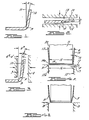
- Figures 1-3 illustrate diagramatically and sequentially the phenomena employed by this invention;
- Figures 4a-4b illustrate the sequential steps for a preferred method of this invention wherein the male punch member is reduced in size for the second striking action;
- Figures 5a-5b illustrate diagramatically sequences of another mode, wherein the female molding member is reduced in size for the second striking action;
- Figure 6 is still another diagramatic view illustrating still another mode of the inventive method herein wherein a single striking step is employed with a tapered female molding member;
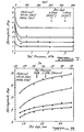
- Figures 7 and 8. are graphical illustrations showing the variation of springback in certain steel sheet materials using the single strike method of the prior art as a function of pad pressure and die gap respectively.
- Figure 9 is a graphical illustration of the variation of springback with a variation in the restrike die gap for the method mode depicted in Figures 4a and 4b;
- Figure 10 is a graphical illustration of springback as function of bottom die gap.
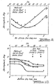
- Figures 11 and 12 are graphical illustrations depicting the variation of springback with die gap for the method mode of Figures 5a and 5b;
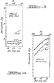
- Figures 13 and 14 are graphical illustrations of the variation of springback with die gap, for the respective materials indicated, when employing the method mode of Figure 6.
- Springback is always present in a bending operation performed on sheet materials that have an elongation of at least 1.5% and have a melting temperature at least twice the temperature at which pressing occurs. Springback cannot be theoretically eliminated since there is little one can do to alter the Young's modulus of a material. The types of sheet metal materials that respond to the method of this invention include all sheet materials that accept a permanent bend as a result of its elongation and solid structure during pressing. This invention is particularly useful for sheet metals such as mild steels (cold rolled, low carbon, hereinafter CRLC), high strength, low alloy steels (hereinafter HSLA), and alloys of aluminum, magnesium and copper.
- This invention has discovered that if the sheet material is deformed at two bend loci (or bend radii), the resultant springback will be substantially reduced and optimally eliminated. The prerequisite for this achievement is the existence of two bend corners in the material applied sequentially. The relative location of the two corners is not a limitation. That is to say, the second bend radius or locus can be located relatively inwardly or outwardly of the first bend locus to achieve the reduction in resultant springback.
- When forming such materials with the use of a mechanical press, it has been found that the conventional mechanisms to compensate or allow for springback are not reliable or effective when working with higher speed presses and higher strength material such as HSLA material having a tensile strength greater than 3515 bar.
- A mechanical press is the machine used for most cold working operations of sheet metal material. Such press consists of a machine frame supporting a bed and a ram, a source of power, and a mechanism to cause the ram to move in line with and at right angles to the bed. A press in and of itself is not sufficient as a production machine, but must be equipped with tools commonly called punch and molding members which together are designed for certain specific operations and forming contour. Typically, as used in the examples of this invention, a male punch member is carried by the ram and is moved in a downward direction to contact the upper surface of the sheet metal lying on a female molding member. The male punch member moves the sheet metal out of its normally flat plane against the contour of the female molding member requiring deep penetration of the male punch member into an opening of the female molding member, forming such complex sections as a U-shape or hat section.
- Presses can be'conveniently classified into two broad types, including hydraulic and mechanical presses. Mechanical presses are desirable, particularly in the automotive industry, because of the improved speed of cycling and thereby greater production. Mechanical presses that are associated with the method of this invention can have a variety of mechanical means for applying power to the ram such as through a crank, a cam, an eccentric, a power screw, a rack and pinion, a knuckle joint, a toggle, and even pneumatic means.
- This invention has discovered that by deforming sheet metal with a press at two spaced bend loci (or bend radii), the resultant springback can be substantially reduced and optimally eliminated. The prerequisite for this achievement is the existence of two bend corners which are spaced apart a small distance typically not easily observable, but in some cases observable. The relative locations of the two corners is not a limitation. This invention achieves such result by way of a mechanical press using typically a male punch member and a female molding member. After a first bending action is completed at a first bend locus, one or both of the members is changed in shape or size to bend the sheet metal at a closely spaced second bend locus. The increments of travel to create both bending actions may be part of a common striking action or may be separated and repeated striking actions.
- Turning to Figure 1, an illustration is given of why the resultant springback is reduced in bending of sheet materials. The elastic strain introduced in each bending operation with this method is significant, one strain being offset against the other strain to control springback. In Figure 1, after a bend is made at a locus A, the
free sidewall 10 of such bend is slanted from the desiredupright plane 11 due to springback. Since the die used to form the bend was designed to form a right angle, the elastic nature of the material has withdrawn thefree sidewall 10 back through an angle of theta (e). If, as shown in Figure 2, the bend is compressed fully between twoparallel blocks free sidewall 10 will be pressed to a flat configuration (or approaching flatness) when the bend B is formed; this is symbolized by dies 8 and 9 moving together. The inclination of thefree wall 10 will have a resultant springback which is the composite of new springback 9B (created by bending at B) counteracted by the residual springback el. This assumes the separation distance between the two bend loci A and B is not significantly noticeable. Thus, the invention herein is a mechanism by which the original springback angle can be converted into a residual springback that works opposite to a subsequent springback increment eB. This reduces the resultant springback significantly (eB - e' ). - This invention is of particular significance to the pressing of sheet metal by mechanical means as opposed to hydraulic presses. Deformation in a mechanical press is carried out with considerable energy which exerts a strong influence on springback in the formation of complex shapes. The term epsilon, which is related to the Young's modulus of materials, controls the springback. As the press speed or strain rate is increased, the overall stress/strain curve is displaced toward higher stress levels. Thus, for a given bending geometry, elastic strain or springback increases with increasing press speed. In addition, the present invention has particular significance with respect to high strength steel. Excessive springback is encountered in production parts made of high strength steels because of the compound effect of high strength and high mechanical press speed.
- A preferred mode for carrying out the inventive method herein is illustrated in Figures 4a and 4b. The first step of the method comprises pressing or striking together, through a first increment, complimentary shaped
male punch member 11 and afemale molding member 12 with a flatsheet metal panel 10 therebetween. The female molding member has anopening 13 with a mouth 13a provided with rounded edge. The opening may be variously shaped such as a slot or other regular geometric configuration. The male punch member has a body with a substantially flatbottom face 14 provided with rounded edges 14a at opposite sides. Thetransverse width 15 offace 14 is designed to be slightly smaller than thewidth 16 ofopening 13, producing aresidual die gap 17 after allowance is made for the thickness 18 of the sheet metal panel. The speed of striking is preferably in excess of 5.08 m/min optimally 9. 15 m/min. - The striking action (see Figure 4a) bends the sheet metal at least at a pair of bend loci identified as A. The
male punch member 11 is designed to form an overall U-shaped configuration in the sheet metal in cooperation with thefemale molding member 12. The preferred range of bending at locus A is 45-95°. The sidewalls 19 of the U are to be desirably parallel after deformation; however, springback from the first bending action causes the sidewalls to be canted outwardly an angle e. - The sheet metal form resulting from the first increment of striking action may have a crown or
curvilinear section 20 formed at the base of the U, between the first bend loci A. This curvilinear section is due to the 4-point bending moment applied to section 28. The sidewalls 24 possess a nonparallel condition because of springback about locus A. The curvilinear section may be avoided by maintaining a positive counter pressure through a counterpad operated inside the female molding member. - The second step (Figure 4b) of the process is to strike the
members - The transverse dimension of the male punch member is changed preferably by 0. 5 to 6. 35 mm when working with most sheet metals. For the embodiment of Figure 4, a smaller male punch member was employed. The pairs of bend loci B were thus located inside the pair of bend loci A. However, use of an enlarged male punch member will also be successful. The
springback angle 6B is reduced by the residual springback el resulting from the flattening of the original bend at A during the formation of the new bend at B. - The die gap (the separation between the side wall of the male punch member and the side wall of the female molding cavity, said walls being parallel to the direction of striking) has some effect in controlling the amount of resultant springback when the male or female member is increased in size for the second striking increment. However, when the male or female member is decreased in size (reduced transverse dimension for the molding cavity or punch body), the bottom die gap during restrike becomes controlling with respect to minimizing resultant springback. Bottom die gap is the distance between the bottom wall or face of the male punch member and the upper face or wall of the counterpad used as part of the female molding member, the walls being transverse to the direction of pressing.
- For purposes of this invention, pressing and striking is defined to mean the bending of sheet metal involving only very limited metal flow, usually restricted at the bend to one side of the sheet being subjected to tension, the other side, of course, being subjected to compression. This phenomenon of bending is to be distinguished from drawing, where the entire cross-section of the sheet metal or member to be shaped is subjected to forces that exceed the elastic limit and thereby permit plastic flow of the metal throughout the entire cross-section.
- Test results that confirm the usefulness of the described method of Figure 4 are shown in Figures 7-10. Two types of sheet metal were subjected to U-channel bending operations in a mechanical press. One type was an aluminum killed, deep drawn steel (AKDQ) having a nominal chemistry by weight percent of about .07% C, .23% Mn, <.02% P, .018% S, and .06% Al; another type was high strength, low alloy (HSLA) having a nominal chemistry of .09% C, .05% Mn, .011% P, .016% S, .08% Al and .23% Ti. Both sheet metals were .031" thick (.8 mm).
- The
male punch member 11 was shaped to have a width between corner radii 14a of about 25.4mm, a length along its face of about 127 mm, and a height along the line of movement of about 76.2 mm . The corner radii 14a of the male punch member was 3.18 mm . Thefemale molding member 12 had anopening 13 complimentary in shape to the male member allowing it to pass thereinto. The edge radii 13a of the mouth entrance to opening 13 was about 6. 35 mm. The members when struck together formed a U-shaped cross-section in the sheet metal member having 90° angles at its bend loci. The die gap was set at varying widths by changing backup shims supporting the split halves of the female molding member. - A single action mechanical press was used to carry the members. The press ram had an average calculated punch speed of 0.15 in/sec.
SAE 30 motor oil was coated on the sheet metal to function as a lubricant during pressing. Springback was measured; the overall experimental error due to variation of sheet metal properties was estimated to be about + 1/2 degree. - Sheet metal pressings were first made using only a single striking action in accordance with the prior art. The die gap (defined to mean the distance between the
sidewalls 20 of the male punch member and the sidewall of the opening in the female molding member, when mated) and the pressure applied to a counterpad 21 (see Figure 5) were varied in the hope of substantially reducing springback. However, as shown in Figure 7, springback decreases with increasing counterpad pressure to a plateau. The plateau varied according to sheet material and die gap. For the AKDQ material, the plateau started at about 2. 5 bar at the 0. 89 mm die gap and about 4. 2 bar at the 1. 27 mm die gap. For the HSLA material, it was about 3.5 bar at the 0. 89 mm die gap and about 1. 4 MPa at the 1, 27 mm die gap. For both steels, springback could not be eliminated by a variation in counterpad pressure. Also, as shown in Figure 8, springback could not be eliminated by a variation in die gap for HSLA steels and substantially so for AKDQ steels. - Sheet metal pressings were then made using the method of Figure 4 whereby a smaller male punch member was used during a restrike action. A first pressing was carried out using a male punch with a transverse dimension of 29.5 mm at a die die gap of 1. 25 mm. The measured wall inclination was 9° for HSLA and 3° 55' for AKDQ steel channels. The channels were restruck with a narrower punch having a transverse dimension of 25.4 mm at varying die gaps, see Figure 9. Springback decreased initially with increasing restrike die gap and reached a minimum at a die gap of about 1. 9 mm in AKDQ steel, but was less in
HSLA 110 steel channels (about 1. 4 mm). - The trend was then reversed with further increase in restrike die gap. Residual springback e' depends on the separation distance between two compression plates, or the die gap in the present instance. The larger the separation distance, the larger is e' and the more is the net reduction of resultant springback. This seems to explain the initial decrease in springback with increasing restrike die gap. After passing the optimum setting, further increases in die gap rendered the female molding member no longer effective to perform a second bend; overall springback, therefore, increased and wall inclination approached its original value. This mode is also effective to reduce the resultant springback by toe-in or negative springback in a wide range of die gaps.
- As a variation, the second bending or restrike action was carried out using an oversized male punch member. The starting channels were preformed with a male punch having a transverse dimension of 25.4 mm at a die gap of 1.25 mm. The width of punch used for restrike was 29.5 mm. Figure 10 shows the observed springback as a function of restrike bottom die gap.
- Turning now to Figure 5, another mode for carrying out the method of this invention is illustrated. The transverse dimension of the male punch for the first and second striking actions, was about the same, but the female molding member had a reduced
opening 13 for the second E striking action, thereby reducing the die gap. The second bend loci B were thus located inside the first bend loci A. Springback again was reduced by this sequence, see Figures 11 and 12.. At the same die gap, springback was always less in the restrike operation than in the original forming operation. It is preferable that the die gap during restrike be on the order of the metal thickness, that is, it should be within the tolerance of + 0.254 mm to the metal thickness. This mode was more effective with HSLA steel than with AKDQ in steel channels. With HSLA steels, reduction in springback increased with increasing wall inclination of the preformed channel. The site of first bending increasingly moved away from the punch as the die gap in the first striking operation increased, thus increasing the separation distance between two corners. - Still another mode for carrying out the method is shown in Figure 6, which comprises the use of a tapered female molding member. Only a single striking action is necessary for this mode, but the concept of a double bend or plural bend technique is still employed. The arrangement of progressively performing a series of bends with one striking operation is graphically represented in tandem in Figure 6. If a line is drawn tangent to the corners of the female molding dies 31 and 32, the resulting configuration is a single female molding member with a tapered wall 33 having an inclination angle as indicated. Resultant springback is reduced by such tapered die. The effect of die gap on springback in female molding members having a wall inclination of 3° and 5° is shown in Figures 13 and 14. For comparison, pressing with parallel walls between punch and mold, with an inclination angle of zero degrees, is shown in broken line in each of these figures. A reduction in springback could be realized in a tapered die as the die gap is decreased to the order of the thickness of the material. This mode eliminates differences in springback between two very different steel sheets which vary because of chemistry or material thicknesses.
- In the double or plural bending technique of this invention, there is little restriction on the process due to material property variation, chemical composition, thickness of the material, or because of the inaccessibility of the male punch in performing a deep, narrow deformation operation. The insensitivity of the present process to the material properties is significant. The observed springback which is a difference between the second springback angle and the residual springback angle of the first bending diminishes this dependence on material properties. This is unobvious because both springback angles are functionally dependent on the material properties.
- It is comprehended within this invention that other types of forming shapes can be carried out by this invention, such as L-shapes, V-shape grooves and hat shaped sections and other forms of pressing, such as by roll forming. The more complex the particular bending operation, the more effective the present method.
Claims (16)
1. A method of mechanically deforming sheet material, characterized by the following steps:
(a) striking together male and female forming members through a first increment of travel to firstly bend said sheet material placed therebetween about at least a first locus to define a deformed sheet material member having a positive springback angle;
(b) striking together male and female forming members through a second increment of travel to secondly bend said deformed sheet material member about at least a second locus spaced from said first locus a distance sufficient to provide a resultant springback angle less than said positive springback angle.
2. The method as in claim 1, characterized in that said resultant springback angle is substantially zero.
3. The method as in claim 1, characterized in that said first bending is carried out independently of said second bending by repeated and separated striking movements, said male forming member for said first striking increment is different in size than the male forming member for said second striking increment, while the female forming member is adjusted in size to maintain a predetermined gap between said members during both striking movements.
4. The method as in claim 1, charaterized in that said spacing distance of step (b) is in the range of 1. 27 mm to 6. 35 mm.
5. The method as in claim 1, characterized in that said sheet material is comprised of high strength, low alloy steel having a yield strength in excess of 3515 bar.
6. The method as in claim 1, characterized in that the sheet material is deformed by said first bending into a U-shape having a pair of first bend loci, said second striking increment defining a pair of second bend loci.
7. The method as in claim 1, characterized in that said first radius of said male forming member for steps (a) and (b) is equal to or less than 3. 18 mm.
8. The method as in claim 1, characterized in that said first bending is carried out independently of said second bending by repeated and separated striking increments, said female forming members for said first and second striking increments having different cross-sectional female configurations, while'the male forming member is adjusted in size to maintain a predetermined gap between said members during both striking increments.
9. The method as in claim 3 or 8, characterized in that the difference in size of the male or female forming member is a reduction in size from the first striking increment, and the predetermined gap is determined by the space between the sides of the forming members parallel to the direction of striking.
10. The method as in claim 3 or 8, characterized in that the difference in size of the male or female forming member is an enlargement from the first striking increment, and the predetermined gap is determined by the space between the sides of the forming members transverse to the direction of striking.
11. The method as in claim 1, characterized in that said first and second striking increments are carried out during the same striking action, said female forming member having a mold cavity defined by walls tapered relative to the direction of striking to effect progressive and sequential bending in said sheet material about a plurality of bend loci while said male forming member is carried into said female forming member.
12. The method as in claim 11, characterized in that said cavity walls are inclined relative to said line of action by an amount in the range of 2-12°.
13. A Method of forming high strength, low alloy sheet steel, characterized by the following steps:
(a) striking said sheet steel with a punch member for movement into a female molding member, said punch member having spaced shoulders to form a pressed section with separated first bend radii;
(b) striking said pressed section with a second punch member again into said female molding member, said second punch member having shoulders spaced apart a distance less than the separation between the bend radii of said pressed section.
14. The method as in claim 13, characterized in that said spacing between said shoulders of said second punch member is less than the spacing between the shoulders of said first punch member by an amount of 1. 27 mm to 6. 35 mm.
15. The method as in claim 12, characterized in that the gap between the portion of said members adjacent the first bend radii in said sheet metal during step (b) is controlled to maximize residual springback.
16. A method of correcting springbach resulting from the deformation of high strength, low alloy steel blanks at a bend radius, said method being characterized by progressively pressing said blank at first and second bend radii adjacent to each other.
Applications Claiming Priority (2)
| Application Number | Priority Date | Filing Date | Title |
|---|---|---|---|
| US22047980A | 1980-12-29 | 1980-12-29 | |
| US220479 | 1980-12-29 |
Publications (1)
| Publication Number | Publication Date |
|---|---|
| EP0055435A2 true EP0055435A2 (en) | 1982-07-07 |
Family
ID=22823700
Family Applications (1)
| Application Number | Title | Priority Date | Filing Date |
|---|---|---|---|
| EP19810110579 Withdrawn EP0055435A2 (en) | 1980-12-29 | 1981-12-18 | Method of reducing springback in mechanically pressed sheet materials - II |
Country Status (5)
| Country | Link |
|---|---|
| EP (1) | EP0055435A2 (en) |
| JP (1) | JPS57112926A (en) |
| AR (1) | AR226399A1 (en) |
| BR (1) | BR8108306A (en) |
| ES (1) | ES506129A0 (en) |
Cited By (6)
| Publication number | Priority date | Publication date | Assignee | Title |
|---|---|---|---|---|
| GB2282090A (en) * | 1993-08-27 | 1995-03-29 | Lvd Co | Adaptive folding |
| US6748788B2 (en) * | 2001-09-26 | 2004-06-15 | Kobe Steel, Ltd. | Method for bending metal plate |
| CN102989854A (en) * | 2012-11-27 | 2013-03-27 | 奇瑞汽车股份有限公司 | Correcting method of misplacement of flanging angle and unevenness of flanging face of automotive L-shaped stamping part |
| EP3165297A1 (en) * | 2015-11-03 | 2017-05-10 | SSAB Technology AB | Bending method |
| CN112845748A (en) * | 2021-01-05 | 2021-05-28 | 浙江申吉钛业股份有限公司 | Method for preparing titanium alloy plate precision bending part based on bending control |
| CN116984461A (en) * | 2023-09-25 | 2023-11-03 | 黑龙江勃锦悍马农业装备制造有限公司 | Stamping device and method for no-tillage planter shell |
Families Citing this family (3)
| Publication number | Priority date | Publication date | Assignee | Title |
|---|---|---|---|---|
| JP4015398B2 (en) * | 2001-09-26 | 2007-11-28 | 株式会社神戸製鋼所 | Metal plate bending method |
| JP5855969B2 (en) * | 2012-02-15 | 2016-02-09 | 株式会社神戸製鋼所 | Metal plate bending method |
| CN114769372A (en) * | 2022-04-20 | 2022-07-22 | 希罗镜下医疗科技发展(上海)有限公司 | Substrate manufacturing and shaping method and substrate |
-
1981
- 1981-10-08 ES ES506129A patent/ES506129A0/en active Granted
- 1981-11-05 JP JP17778681A patent/JPS57112926A/en active Pending
- 1981-12-18 EP EP19810110579 patent/EP0055435A2/en not_active Withdrawn
- 1981-12-21 BR BR8108306A patent/BR8108306A/en unknown
- 1981-12-29 AR AR28798881A patent/AR226399A1/en active
Cited By (14)
| Publication number | Priority date | Publication date | Assignee | Title |
|---|---|---|---|---|
| GB2282090A (en) * | 1993-08-27 | 1995-03-29 | Lvd Co | Adaptive folding |
| GB2282090B (en) * | 1993-08-27 | 1997-08-06 | Lvd Co | Adaptive folding |
| US5829288A (en) * | 1993-08-27 | 1998-11-03 | L.V.D. Company N.V. | Adaptive folding |
| US6748788B2 (en) * | 2001-09-26 | 2004-06-15 | Kobe Steel, Ltd. | Method for bending metal plate |
| CN102989854A (en) * | 2012-11-27 | 2013-03-27 | 奇瑞汽车股份有限公司 | Correcting method of misplacement of flanging angle and unevenness of flanging face of automotive L-shaped stamping part |
| CN102989854B (en) * | 2012-11-27 | 2014-10-01 | 奇瑞汽车股份有限公司 | Correcting method of misplacement of flanging angle and unevenness of flanging face of automotive L-shaped stamping part |
| EP3165297A1 (en) * | 2015-11-03 | 2017-05-10 | SSAB Technology AB | Bending method |
| WO2017076946A1 (en) | 2015-11-03 | 2017-05-11 | Ssab Technology Ab | Bending method |
| CN108472705A (en) * | 2015-11-03 | 2018-08-31 | 瑞典钢铁技术有限公司 | Bending method |
| CN108472705B (en) * | 2015-11-03 | 2020-03-06 | 瑞典钢铁技术有限公司 | Bending method |
| US11633770B2 (en) | 2015-11-03 | 2023-04-25 | Ssab Technology Ab | Bending method |
| CN112845748A (en) * | 2021-01-05 | 2021-05-28 | 浙江申吉钛业股份有限公司 | Method for preparing titanium alloy plate precision bending part based on bending control |
| CN116984461A (en) * | 2023-09-25 | 2023-11-03 | 黑龙江勃锦悍马农业装备制造有限公司 | Stamping device and method for no-tillage planter shell |
| CN116984461B (en) * | 2023-09-25 | 2023-12-19 | 黑龙江勃锦悍马农业装备制造有限公司 | Stamping device and method for no-tillage planter shell |
Also Published As
| Publication number | Publication date |
|---|---|
| JPS57112926A (en) | 1982-07-14 |
| AR226399A1 (en) | 1982-06-30 |
| ES8304454A1 (en) | 1983-03-01 |
| BR8108306A (en) | 1982-10-05 |
| ES506129A0 (en) | 1983-03-01 |
Similar Documents
| Publication | Publication Date | Title |
|---|---|---|
| EP0055436B1 (en) | Method of reducing springback in mechanically pressed sheet materials | |
| US10710136B2 (en) | Press-forming apparatus and press-forming method | |
| JP3415358B2 (en) | Composite mold and composite molding method | |
| JP7617399B2 (en) | Pressing device and method for manufacturing press-molded products | |
| EP0055435A2 (en) | Method of reducing springback in mechanically pressed sheet materials - II | |
| KR20190119100A (en) | Press molding apparatus and manufacturing method of press molded article | |
| WO2018180711A1 (en) | Press mold device and production method for press-molded articles | |
| US20220371070A1 (en) | Method for manufacturing press-formed article, press-formed article, and press-forming apparatus | |
| CN113226584B (en) | Press forming method | |
| JP7564448B2 (en) | Manufacturing method and manufacturing equipment for press-molded products | |
| EP0799656B1 (en) | Method for producing pipe having polygon-shaped closed cross-section and device therefor | |
| AU587887B2 (en) | Press forming sheet metal | |
| EP4321269A1 (en) | Press forming method | |
| JPH06246355A (en) | Method for bending high tensile steel sheet | |
| GB2094681A (en) | Bending | |
| CA1193145A (en) | Method of reducing curling in pressed sheet materials | |
| JP4232451B2 (en) | Press working method with excellent shape freezing | |
| WO2018180710A1 (en) | Press mold device and production method for press-molded articles | |
| RU2110348C1 (en) | Method of making sections mainly w-shaped ones | |
| JPH04172128A (en) | Method for bending | |
| JP3158586B2 (en) | Method of forming member having H-shaped cross section | |
| JP3997907B2 (en) | Pressing method with excellent shape freezing | |
| JP4461843B2 (en) | Processing method of metal plate with less springback | |
| JP7476935B2 (en) | Manufacturing method of press-molded products | |
| JP7647714B2 (en) | Press molding method and manufacturing method of press molded product |
Legal Events
| Date | Code | Title | Description |
|---|---|---|---|
| PUAI | Public reference made under article 153(3) epc to a published international application that has entered the european phase |
Free format text: ORIGINAL CODE: 0009012 |
|
| AK | Designated contracting states |
Designated state(s): DE FR GB IT SE |
|
| STAA | Information on the status of an ep patent application or granted ep patent |
Free format text: STATUS: THE APPLICATION HAS BEEN WITHDRAWN |
|
| 18W | Application withdrawn |
Withdrawal date: 19820908 |
|
| R18W | Application withdrawn (corrected) |
Effective date: 19820908 |
|
| RIN1 | Information on inventor provided before grant (corrected) |
Inventor name: LIU, YOU CAO |