EP0055435A2 - Verfahren zum Vermindern des Rückspringens von mechanisch gepresstem plattenförmigem Material - Google Patents
Verfahren zum Vermindern des Rückspringens von mechanisch gepresstem plattenförmigem Material Download PDFInfo
- Publication number
- EP0055435A2 EP0055435A2 EP19810110579 EP81110579A EP0055435A2 EP 0055435 A2 EP0055435 A2 EP 0055435A2 EP 19810110579 EP19810110579 EP 19810110579 EP 81110579 A EP81110579 A EP 81110579A EP 0055435 A2 EP0055435 A2 EP 0055435A2
- Authority
- EP
- European Patent Office
- Prior art keywords
- striking
- bend
- springback
- male
- female
- Prior art date
- Legal status (The legal status is an assumption and is not a legal conclusion. Google has not performed a legal analysis and makes no representation as to the accuracy of the status listed.)
- Withdrawn
Links
- 239000000463 material Substances 0.000 title claims abstract description 57
- 238000000034 method Methods 0.000 title claims abstract description 43
- 238000005452 bending Methods 0.000 claims description 35
- 229910052751 metal Inorganic materials 0.000 claims description 34
- 239000002184 metal Substances 0.000 claims description 34
- 238000000465 moulding Methods 0.000 claims description 26
- 230000009471 action Effects 0.000 claims description 22
- 229910000831 Steel Inorganic materials 0.000 claims description 19
- 239000010959 steel Substances 0.000 claims description 19
- 238000003825 pressing Methods 0.000 claims description 15
- 230000009467 reduction Effects 0.000 claims description 6
- 238000000926 separation method Methods 0.000 claims description 6
- 229910045601 alloy Inorganic materials 0.000 claims description 5
- 239000000956 alloy Substances 0.000 claims description 5
- 230000000694 effects Effects 0.000 claims description 4
- 230000000750 progressive effect Effects 0.000 claims description 2
- 229910000851 Alloy steel Inorganic materials 0.000 claims 2
- 238000004519 manufacturing process Methods 0.000 description 5
- 229910052782 aluminium Inorganic materials 0.000 description 4
- 229910052799 carbon Inorganic materials 0.000 description 3
- 230000006835 compression Effects 0.000 description 3
- 238000007906 compression Methods 0.000 description 3
- 230000003247 decreasing effect Effects 0.000 description 3
- 230000007246 mechanism Effects 0.000 description 3
- 150000002739 metals Chemical class 0.000 description 3
- 230000008569 process Effects 0.000 description 3
- XAGFODPZIPBFFR-UHFFFAOYSA-N aluminium Chemical compound [Al] XAGFODPZIPBFFR-UHFFFAOYSA-N 0.000 description 2
- 230000015572 biosynthetic process Effects 0.000 description 2
- 230000008859 change Effects 0.000 description 2
- 230000002508 compound effect Effects 0.000 description 2
- 230000007423 decrease Effects 0.000 description 2
- 239000007769 metal material Substances 0.000 description 2
- 239000000203 mixture Substances 0.000 description 2
- 239000000126 substance Substances 0.000 description 2
- OKTJSMMVPCPJKN-UHFFFAOYSA-N Carbon Chemical compound [C] OKTJSMMVPCPJKN-UHFFFAOYSA-N 0.000 description 1
- RYGMFSIKBFXOCR-UHFFFAOYSA-N Copper Chemical compound [Cu] RYGMFSIKBFXOCR-UHFFFAOYSA-N 0.000 description 1
- 229910000922 High-strength low-alloy steel Inorganic materials 0.000 description 1
- FYYHWMGAXLPEAU-UHFFFAOYSA-N Magnesium Chemical compound [Mg] FYYHWMGAXLPEAU-UHFFFAOYSA-N 0.000 description 1
- 238000013459 approach Methods 0.000 description 1
- 239000002131 composite material Substances 0.000 description 1
- 229910052802 copper Inorganic materials 0.000 description 1
- 239000010949 copper Substances 0.000 description 1
- 230000001351 cycling effect Effects 0.000 description 1
- 230000001419 dependent effect Effects 0.000 description 1
- 239000000314 lubricant Substances 0.000 description 1
- 229910052749 magnesium Inorganic materials 0.000 description 1
- 239000011777 magnesium Substances 0.000 description 1
- 238000002844 melting Methods 0.000 description 1
- 230000008018 melting Effects 0.000 description 1
- 239000010705 motor oil Substances 0.000 description 1
- 230000035515 penetration Effects 0.000 description 1
- 238000013001 point bending Methods 0.000 description 1
- 239000007787 solid Substances 0.000 description 1
- 238000005482 strain hardening Methods 0.000 description 1
Images


Classifications
-
- B—PERFORMING OPERATIONS; TRANSPORTING
- B21—MECHANICAL METAL-WORKING WITHOUT ESSENTIALLY REMOVING MATERIAL; PUNCHING METAL
- B21D—WORKING OR PROCESSING OF SHEET METAL OR METAL TUBES, RODS OR PROFILES WITHOUT ESSENTIALLY REMOVING MATERIAL; PUNCHING METAL
- B21D11/00—Bending not restricted to forms of material mentioned in only one of groups B21D5/00, B21D7/00, B21D9/00; Bending not provided for in groups B21D5/00 - B21D9/00; Twisting
- B21D11/20—Bending sheet metal, not otherwise provided for
-
- B—PERFORMING OPERATIONS; TRANSPORTING
- B21—MECHANICAL METAL-WORKING WITHOUT ESSENTIALLY REMOVING MATERIAL; PUNCHING METAL
- B21D—WORKING OR PROCESSING OF SHEET METAL OR METAL TUBES, RODS OR PROFILES WITHOUT ESSENTIALLY REMOVING MATERIAL; PUNCHING METAL
- B21D5/00—Bending sheet metal along straight lines, e.g. to form simple curves
- B21D5/01—Bending sheet metal along straight lines, e.g. to form simple curves between rams and anvils or abutments
Definitions
- Springback is a phenomenon always present in the bending of metal. Bending operations for sheet metal are typically carried out by the use of presses broadly classified by the source of power as hydraulic or mechanical. Certain alternatives are available when using hydraulic presses to control springback, within tolerable limits, because of the lower strain rate involved. However, more efficient and rapid production can be achieved with mechanical presses which use higher strain rates resulting from high speed ram movement.
- Springback is the natural tendency of the material to revert to its original shape after the bending force has been removed. It has been generally believed heretofore that the springback is proportional to a certain group of parameters which include the bending radius, the thickness of the product material and the hardness of the material. It has been conventional for tool designers to correct such springback by (a) overcompensating through an overbend whereby the product will relax to a shape that is more precisely desired upon relief of the bending force, or (b) restriking the material in the same die at the same bend point to encourage the material to more closely conform to the desired die configuration.
- the invention is a method of mechanically deforming sheet material to eliminate or substantially reduce the apparent springback of the material, irrespective of a variance of material properties, chemical composition, thickness of the material and speed of the deforming member.
- the invention uses progressive pressing of sheet material at adjacent but spaced bend radii to achieve this result. Residual springback from the first striking action subtracts from the springback of the second striking action to significantly reduce the resultant springback in the product.
- the method comprises (a) striking together male and female forming members through a first increment of travel to firstly bend the sheet material placed therebetween about at least a first locus to define a first deformed sheet material member having a positive springback angle, and (b) striking together male and female forming members through a second increment of travel to secondly bend said first deformed sheet material member about at least a second locus spaced from said first locus a distance to provide a reduced resultant springback angle.
- One mode employs repeated striking movements to separately provide the first and second bending; each female member and male member is changed in cross-sectional size for the second striking movement to create the spacing needed between the first and second bend radii.
- Such change may be an enlargement or reduction because the second bend radius can be located to either side of the first bend radius but within a controlled spacing, preferably of 0.5 to 6. 4 mm.
- the gap can be in a wide range for the first striking action, preferably about 1.5 x 2.0 times the thickness of the material.
- the gap for the second striking increment is optimally equal to the thickness of the material and operably in a range of 1.0-1.5 times the thickness of the material. It has been found desirable to limit the corner radius of said members to about the thickness of the material.
- Another mode is to form the female die with tapered walls and to carry out the first and second bending as part of a continuous pressing motion.
- bending of the sheet material at a first locus would occur during the initial increment of travel of the male member into the tapered female member and the second or subsequent bendings would occur as the male member moves through additional increments of travel down along the tapered walls of the female member, creating bending at different loci.
- bending will occur about a plurality of loci as the male die is moved during a single striking action to mate with the female member.
- Springback is always present in a bending operation performed on sheet materials that have an elongation of at least 1.5% and have a melting temperature at least twice the temperature at which pressing occurs. Springback cannot be theoretically eliminated since there is little one can do to alter the Young's modulus of a material.
- the types of sheet metal materials that respond to the method of this invention include all sheet materials that accept a permanent bend as a result of its elongation and solid structure during pressing. This invention is particularly useful for sheet metals such as mild steels (cold rolled, low carbon, hereinafter CRLC), high strength, low alloy steels (hereinafter HSLA), and alloys of aluminum, magnesium and copper.
- a mechanical press is the machine used for most cold working operations of sheet metal material.
- Such press consists of a machine frame supporting a bed and a ram, a source of power, and a mechanism to cause the ram to move in line with and at right angles to the bed.
- a press in and of itself is not sufficient as a production machine, but must be equipped with tools commonly called punch and molding members which together are designed for certain specific operations and forming contour.
- a male punch member is carried by the ram and is moved in a downward direction to contact the upper surface of the sheet metal lying on a female molding member. The male punch member moves the sheet metal out of its normally flat plane against the contour of the female molding member requiring deep penetration of the male punch member into an opening of the female molding member, forming such complex sections as a U-shape or hat section.
- Presses can be'conveniently classified into two broad types, including hydraulic and mechanical presses.
- Mechanical presses are desirable, particularly in the automotive industry, because of the improved speed of cycling and thereby greater production.
- Mechanical presses that are associated with the method of this invention can have a variety of mechanical means for applying power to the ram such as through a crank, a cam, an eccentric, a power screw, a rack and pinion, a knuckle joint, a toggle, and even pneumatic means.
- This invention has discovered that by deforming sheet metal with a press at two spaced bend loci (or bend radii), the resultant springback can be substantially reduced and optimally eliminated.
- the prerequisite for this achievement is the existence of two bend corners which are spaced apart a small distance typically not easily observable, but in some cases observable.
- the relative locations of the two corners is not a limitation.
- This invention achieves such result by way of a mechanical press using typically a male punch member and a female molding member. After a first bending action is completed at a first bend locus, one or both of the members is changed in shape or size to bend the sheet metal at a closely spaced second bend locus.
- the increments of travel to create both bending actions may be part of a common striking action or may be separated and repeated striking actions.
- This invention is of particular significance to the pressing of sheet metal by mechanical means as opposed to hydraulic presses. Deformation in a mechanical press is carried out with considerable energy which exerts a strong influence on springback in the formation of complex shapes.
- the term epsilon which is related to the Young's modulus of materials, controls the springback. As the press speed or strain rate is increased, the overall stress/strain curve is displaced toward higher stress levels. Thus, for a given bending geometry, elastic strain or springback increases with increasing press speed.
- the present invention has particular significance with respect to high strength steel. Excessive springback is encountered in production parts made of high strength steels because of the compound effect of high strength and high mechanical press speed.
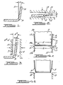
- the first step of the method comprises pressing or striking together, through a first increment, complimentary shaped male punch member 11 and a female molding member 12 with a flat sheet metal panel 10 therebetween.
- the female molding member has an opening 13 with a mouth 13a provided with rounded edge.
- the opening may be variously shaped such as a slot or other regular geometric configuration.
- the male punch member has a body with a substantially flat bottom face 14 provided with rounded edges 14a at opposite sides.
- the transverse width 15 of face 14 is designed to be slightly smaller than the width 16 of opening 13, producing a residual die gap 17 after allowance is made for the thickness 18 of the sheet metal panel.
- the speed of striking is preferably in excess of 5.08 m/min optimally 9. 15 m/min.
- the striking action bends the sheet metal at least at a pair of bend loci identified as A.
- the male punch member 11 is designed to form an overall U-shaped configuration in the sheet metal in cooperation with the female molding member 12.
- the preferred range of bending at locus A is 45-95°.
- the sidewalls 19 of the U are to be desirably parallel after deformation; however, springback from the first bending action causes the sidewalls to be canted outwardly an angle e.
- the sheet metal form resulting from the first increment of striking action may have a crown or curvilinear section 20 formed at the base of the U, between the first bend loci A.
- This curvilinear section is due to the 4-point bending moment applied to section 28.
- the sidewalls 24 possess a nonparallel condition because of springback about locus A.
- the curvilinear section may be avoided by maintaining a positive counter pressure through a counterpad operated inside the female molding member.
- the second step ( Figure 4b) of the process is to strike the members 11 and 12 together through a second increment of travel with the first bent sheet metal therebetween (having bends at loci A).
- This step is preferably carried out by restriking the members, using a different sized male punch member and using different sized female molding member responding to the change in size of the male member.
- the sheet metal is secondly bent at a pair of bend loci B, each spaced a small distance from a bend locus A.
- the transverse dimension of the male punch member is changed preferably by 0. 5 to 6. 35 mm when working with most sheet metals.
- a smaller male punch member was employed.
- the pairs of bend loci B were thus located inside the pair of bend loci A.
- use of an enlarged male punch member will also be successful.
- the springback angle 6 B is reduced by the residual springback e l resulting from the flattening of the original bend at A during the formation of the new bend at B.
- the die gap (the separation between the side wall of the male punch member and the side wall of the female molding cavity, said walls being parallel to the direction of striking) has some effect in controlling the amount of resultant springback when the male or female member is increased in size for the second striking increment.
- the bottom die gap during restrike becomes controlling with respect to minimizing resultant springback.
- Bottom die gap is the distance between the bottom wall or face of the male punch member and the upper face or wall of the counterpad used as part of the female molding member, the walls being transverse to the direction of pressing.
- pressing and striking is defined to mean the bending of sheet metal involving only very limited metal flow, usually restricted at the bend to one side of the sheet being subjected to tension, the other side, of course, being subjected to compression.
- This phenomenon of bending is to be distinguished from drawing, where the entire cross-section of the sheet metal or member to be shaped is subjected to forces that exceed the elastic limit and thereby permit plastic flow of the metal throughout the entire cross-section.
- the male punch member 11 was shaped to have a width between corner radii 14a of about 25.4mm, a length along its face of about 127 mm, and a height along the line of movement of about 76.2 mm .
- the corner radii 14a of the male punch member was 3.18 mm .
- the female molding member 12 had an opening 13 complimentary in shape to the male member allowing it to pass thereinto.
- the edge radii 13a of the mouth entrance to opening 13 was about 6. 35 mm.
- the members when struck together formed a U-shaped cross-section in the sheet metal member having 90° angles at its bend loci.
- the die gap was set at varying widths by changing backup shims supporting the split halves of the female molding member.
- a single action mechanical press was used to carry the members.
- the press ram had an average calculated punch speed of 0.15 in/sec.
- SAE 30 motor oil was coated on the sheet metal to function as a lubricant during pressing. Springback was measured; the overall experimental error due to variation of sheet metal properties was estimated to be about + 1/2 degree.
- Sheet metal pressings were first made using only a single striking action in accordance with the prior art.
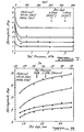
- the die gap (defined to mean the distance between the sidewalls 20 of the male punch member and the sidewall of the opening in the female molding member, when mated) and the pressure applied to a counterpad 21 (see Figure 5) were varied in the hope of substantially reducing springback.
- springback decreases with increasing counterpad pressure to a plateau.
- the plateau varied according to sheet material and die gap.
- the plateau started at about 2. 5 bar at the 0. 89 mm die gap and about 4. 2 bar at the 1. 27 mm die gap.
- For the HSLA material it was about 3.5 bar at the 0. 89 mm die gap and about 1.
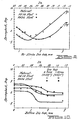
- springback could not be eliminated by a variation in counterpad pressure. Also, as shown in Figure 8, springback could not be eliminated by a variation in die gap for HSLA steels and substantially so for AKDQ steels.
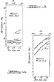
- Sheet metal pressings were then made using the method of Figure 4 whereby a smaller male punch member was used during a restrike action.
- a first pressing was carried out using a male punch with a transverse dimension of 29.5 mm at a die die gap of 1. 25 mm.
- the measured wall inclination was 9° for HSLA and 3° 55' for AKDQ steel channels.
- the channels were restruck with a narrower punch having a transverse dimension of 25.4 mm at varying die gaps, see Figure 9.
- Springback decreased initially with increasing restrike die gap and reached a minimum at a die gap of about 1. 9 mm in AKDQ steel, but was less in HSLA 110 steel channels (about 1. 4 mm).
- the second bending or restrike action was carried out using an oversized male punch member.
- the starting channels were preformed with a male punch having a transverse dimension of 25.4 mm at a die gap of 1.25 mm.
- the width of punch used for restrike was 29.5 mm.
- Figure 10 shows the observed springback as a function of restrike bottom die gap.
- Figure 6 Still another mode for carrying out the method is shown in Figure 6, which comprises the use of a tapered female molding member. Only a single striking action is necessary for this mode, but the concept of a double bend or plural bend technique is still employed.
- the arrangement of progressively performing a series of bends with one striking operation is graphically represented in tandem in Figure 6. If a line is drawn tangent to the corners of the female molding dies 31 and 32, the resulting configuration is a single female molding member with a tapered wall 33 having an inclination angle as indicated. Resultant springback is reduced by such tapered die.
- the effect of die gap on springback in female molding members having a wall inclination of 3° and 5° is shown in Figures 13 and 14.
Landscapes
- Engineering & Computer Science (AREA)
- Mechanical Engineering (AREA)
- Bending Of Plates, Rods, And Pipes (AREA)
Applications Claiming Priority (2)
| Application Number | Priority Date | Filing Date | Title |
|---|---|---|---|
| US22047980A | 1980-12-29 | 1980-12-29 | |
| US220479 | 1980-12-29 |
Publications (1)
| Publication Number | Publication Date |
|---|---|
| EP0055435A2 true EP0055435A2 (de) | 1982-07-07 |
Family
ID=22823700
Family Applications (1)
| Application Number | Title | Priority Date | Filing Date |
|---|---|---|---|
| EP19810110579 Withdrawn EP0055435A2 (de) | 1980-12-29 | 1981-12-18 | Verfahren zum Vermindern des Rückspringens von mechanisch gepresstem plattenförmigem Material |
Country Status (5)
| Country | Link |
|---|---|
| EP (1) | EP0055435A2 (de) |
| JP (1) | JPS57112926A (de) |
| AR (1) | AR226399A1 (de) |
| BR (1) | BR8108306A (de) |
| ES (1) | ES506129A0 (de) |
Cited By (6)
| Publication number | Priority date | Publication date | Assignee | Title |
|---|---|---|---|---|
| GB2282090A (en) * | 1993-08-27 | 1995-03-29 | Lvd Co | Adaptive folding |
| US6748788B2 (en) * | 2001-09-26 | 2004-06-15 | Kobe Steel, Ltd. | Method for bending metal plate |
| CN102989854A (zh) * | 2012-11-27 | 2013-03-27 | 奇瑞汽车股份有限公司 | 汽车l型冲压件翻边角度不到位和翻边面不平的整改方法 |
| EP3165297A1 (de) * | 2015-11-03 | 2017-05-10 | SSAB Technology AB | Biegeverfahren |
| CN112845748A (zh) * | 2021-01-05 | 2021-05-28 | 浙江申吉钛业股份有限公司 | 基于控制弯曲的钛合金板材精密弯曲零件制备方法 |
| CN116984461A (zh) * | 2023-09-25 | 2023-11-03 | 黑龙江勃锦悍马农业装备制造有限公司 | 一种用于免耕播种机壳体的冲压装置及方法 |
Families Citing this family (3)
| Publication number | Priority date | Publication date | Assignee | Title |
|---|---|---|---|---|
| JP4015398B2 (ja) * | 2001-09-26 | 2007-11-28 | 株式会社神戸製鋼所 | 金属板の曲げ成形方法 |
| JP5855969B2 (ja) * | 2012-02-15 | 2016-02-09 | 株式会社神戸製鋼所 | 金属板の曲げ加工方法 |
| CN114769372A (zh) * | 2022-04-20 | 2022-07-22 | 希罗镜下医疗科技发展(上海)有限公司 | 一种基底制作定形方法及基底 |
-
1981
- 1981-10-08 ES ES506129A patent/ES506129A0/es active Granted
- 1981-11-05 JP JP17778681A patent/JPS57112926A/ja active Pending
- 1981-12-18 EP EP19810110579 patent/EP0055435A2/de not_active Withdrawn
- 1981-12-21 BR BR8108306A patent/BR8108306A/pt unknown
- 1981-12-29 AR AR28798881A patent/AR226399A1/es active
Cited By (14)
| Publication number | Priority date | Publication date | Assignee | Title |
|---|---|---|---|---|
| GB2282090A (en) * | 1993-08-27 | 1995-03-29 | Lvd Co | Adaptive folding |
| GB2282090B (en) * | 1993-08-27 | 1997-08-06 | Lvd Co | Adaptive folding |
| US5829288A (en) * | 1993-08-27 | 1998-11-03 | L.V.D. Company N.V. | Adaptive folding |
| US6748788B2 (en) * | 2001-09-26 | 2004-06-15 | Kobe Steel, Ltd. | Method for bending metal plate |
| CN102989854A (zh) * | 2012-11-27 | 2013-03-27 | 奇瑞汽车股份有限公司 | 汽车l型冲压件翻边角度不到位和翻边面不平的整改方法 |
| CN102989854B (zh) * | 2012-11-27 | 2014-10-01 | 奇瑞汽车股份有限公司 | 汽车l型冲压件翻边角度不到位和翻边面不平的整改方法 |
| EP3165297A1 (de) * | 2015-11-03 | 2017-05-10 | SSAB Technology AB | Biegeverfahren |
| WO2017076946A1 (en) | 2015-11-03 | 2017-05-11 | Ssab Technology Ab | Bending method |
| CN108472705A (zh) * | 2015-11-03 | 2018-08-31 | 瑞典钢铁技术有限公司 | 弯曲方法 |
| CN108472705B (zh) * | 2015-11-03 | 2020-03-06 | 瑞典钢铁技术有限公司 | 弯曲方法 |
| US11633770B2 (en) | 2015-11-03 | 2023-04-25 | Ssab Technology Ab | Bending method |
| CN112845748A (zh) * | 2021-01-05 | 2021-05-28 | 浙江申吉钛业股份有限公司 | 基于控制弯曲的钛合金板材精密弯曲零件制备方法 |
| CN116984461A (zh) * | 2023-09-25 | 2023-11-03 | 黑龙江勃锦悍马农业装备制造有限公司 | 一种用于免耕播种机壳体的冲压装置及方法 |
| CN116984461B (zh) * | 2023-09-25 | 2023-12-19 | 黑龙江勃锦悍马农业装备制造有限公司 | 一种用于免耕播种机壳体的冲压装置及方法 |
Also Published As
| Publication number | Publication date |
|---|---|
| JPS57112926A (en) | 1982-07-14 |
| AR226399A1 (es) | 1982-06-30 |
| ES8304454A1 (es) | 1983-03-01 |
| BR8108306A (pt) | 1982-10-05 |
| ES506129A0 (es) | 1983-03-01 |
Similar Documents
| Publication | Publication Date | Title |
|---|---|---|
| EP0055436B1 (de) | Verfahren zum Vermindern des Rückspringens von mechanisch gepresstem plattenförmigem Material | |
| US10710136B2 (en) | Press-forming apparatus and press-forming method | |
| JP3415358B2 (ja) | 複合成形型および複合成形方法 | |
| JP7617399B2 (ja) | プレス装置及びプレス成形品の製造方法 | |
| EP0055435A2 (de) | Verfahren zum Vermindern des Rückspringens von mechanisch gepresstem plattenförmigem Material | |
| KR20190119100A (ko) | 프레스 성형 장치 및 프레스 성형품의 제조 방법 | |
| WO2018180711A1 (ja) | プレス成形装置及びプレス成形品の製造方法 | |
| US20220371070A1 (en) | Method for manufacturing press-formed article, press-formed article, and press-forming apparatus | |
| CN113226584B (zh) | 冲压成形方法 | |
| JP7564448B2 (ja) | プレス成形品の製造方法及び製造設備 | |
| EP0799656B1 (de) | Verfahren und Vorrichtung zum Formen von Rohren mit polygonalen Querschnitten | |
| AU587887B2 (en) | Press forming sheet metal | |
| EP4321269A1 (de) | Pressformverfahren | |
| JPH06246355A (ja) | 高張力鋼板の曲げ加工方法 | |
| GB2094681A (en) | Bending | |
| CA1193145A (en) | Method of reducing curling in pressed sheet materials | |
| JP4232451B2 (ja) | 形状凍結性に優れたプレス加工方法 | |
| WO2018180710A1 (ja) | プレス成形装置及びプレス成形品の製造方法 | |
| RU2110348C1 (ru) | Способ изготовления профилей преимущественно w-образного сечения | |
| JPH04172128A (ja) | 曲げ成形方法 | |
| JP3158586B2 (ja) | H形状断面を有する部材の成形方法 | |
| JP3997907B2 (ja) | 形状凍結性に優れたプレス加工方法 | |
| JP4461843B2 (ja) | スプリングバックの少ない金属板の加工方法 | |
| JP7476935B2 (ja) | プレス成形品の製造方法 | |
| JP7647714B2 (ja) | プレス成形方法及びプレス成形品の製造方法 |
Legal Events
| Date | Code | Title | Description |
|---|---|---|---|
| PUAI | Public reference made under article 153(3) epc to a published international application that has entered the european phase |
Free format text: ORIGINAL CODE: 0009012 |
|
| AK | Designated contracting states |
Designated state(s): DE FR GB IT SE |
|
| STAA | Information on the status of an ep patent application or granted ep patent |
Free format text: STATUS: THE APPLICATION HAS BEEN WITHDRAWN |
|
| 18W | Application withdrawn |
Withdrawal date: 19820908 |
|
| R18W | Application withdrawn (corrected) |
Effective date: 19820908 |
|
| RIN1 | Information on inventor provided before grant (corrected) |
Inventor name: LIU, YOU CAO |