EP0055482B1 - Kraftstoffeinspritzvorrichtung für Brennkraftmaschine mit innerer Verbrennung - Google Patents
Kraftstoffeinspritzvorrichtung für Brennkraftmaschine mit innerer Verbrennung Download PDFInfo
- Publication number
- EP0055482B1 EP0055482B1 EP81110799A EP81110799A EP0055482B1 EP 0055482 B1 EP0055482 B1 EP 0055482B1 EP 81110799 A EP81110799 A EP 81110799A EP 81110799 A EP81110799 A EP 81110799A EP 0055482 B1 EP0055482 B1 EP 0055482B1
- Authority
- EP
- European Patent Office
- Prior art keywords
- fuel
- air
- fuel injection
- valve
- scaling
- Prior art date
- Legal status (The legal status is an assumption and is not a legal conclusion. Google has not performed a legal analysis and makes no representation as to the accuracy of the status listed.)
- Expired
Links
- 239000000446 fuel Substances 0.000 title claims description 173
- 238000002347 injection Methods 0.000 title claims description 54
- 239000007924 injection Substances 0.000 title claims description 54
- 238000002485 combustion reaction Methods 0.000 title claims description 14
- 230000001133 acceleration Effects 0.000 claims description 23
- 238000011144 upstream manufacturing Methods 0.000 claims description 15
- 230000003247 decreasing effect Effects 0.000 claims description 10
- 230000007423 decrease Effects 0.000 claims description 8
- 238000010586 diagram Methods 0.000 description 13
- 230000006835 compression Effects 0.000 description 8
- 238000007906 compression Methods 0.000 description 8
- 239000000203 mixture Substances 0.000 description 8
- 238000012937 correction Methods 0.000 description 7
- 238000013459 approach Methods 0.000 description 5
- 230000001105 regulatory effect Effects 0.000 description 5
- 230000008016 vaporization Effects 0.000 description 5
- 238000010276 construction Methods 0.000 description 4
- 239000007789 gas Substances 0.000 description 4
- XLYOFNOQVPJJNP-UHFFFAOYSA-N water Substances O XLYOFNOQVPJJNP-UHFFFAOYSA-N 0.000 description 4
- 238000009834 vaporization Methods 0.000 description 3
- QVGXLLKOCUKJST-UHFFFAOYSA-N atomic oxygen Chemical compound [O] QVGXLLKOCUKJST-UHFFFAOYSA-N 0.000 description 2
- 230000001276 controlling effect Effects 0.000 description 2
- 239000000498 cooling water Substances 0.000 description 2
- 239000002828 fuel tank Substances 0.000 description 2
- 230000007246 mechanism Effects 0.000 description 2
- 239000001301 oxygen Substances 0.000 description 2
- 229910052760 oxygen Inorganic materials 0.000 description 2
- 230000002093 peripheral effect Effects 0.000 description 2
- 230000010349 pulsation Effects 0.000 description 2
- 230000001174 ascending effect Effects 0.000 description 1
- 238000000034 method Methods 0.000 description 1
- 230000001737 promoting effect Effects 0.000 description 1
Images


Classifications
-
- F—MECHANICAL ENGINEERING; LIGHTING; HEATING; WEAPONS; BLASTING
- F02—COMBUSTION ENGINES; HOT-GAS OR COMBUSTION-PRODUCT ENGINE PLANTS
- F02M—SUPPLYING COMBUSTION ENGINES IN GENERAL WITH COMBUSTIBLE MIXTURES OR CONSTITUENTS THEREOF
- F02M45/00—Fuel-injection apparatus characterised by having a cyclic delivery of specific time/pressure or time/quantity relationship
-
- G—PHYSICS
- G01—MEASURING; TESTING
- G01F—MEASURING VOLUME, VOLUME FLOW, MASS FLOW OR LIQUID LEVEL; METERING BY VOLUME
- G01F1/00—Measuring the volume flow or mass flow of fluid or fluent solid material wherein the fluid passes through a meter in a continuous flow
- G01F1/68—Measuring the volume flow or mass flow of fluid or fluent solid material wherein the fluid passes through a meter in a continuous flow by using thermal effects
- G01F1/684—Structural arrangements; Mounting of elements, e.g. in relation to fluid flow
- G01F1/6842—Structural arrangements; Mounting of elements, e.g. in relation to fluid flow with means for influencing the fluid flow
-
- F—MECHANICAL ENGINEERING; LIGHTING; HEATING; WEAPONS; BLASTING
- F02—COMBUSTION ENGINES; HOT-GAS OR COMBUSTION-PRODUCT ENGINE PLANTS
- F02D—CONTROLLING COMBUSTION ENGINES
- F02D41/00—Electrical control of supply of combustible mixture or its constituents
- F02D41/02—Circuit arrangements for generating control signals
- F02D41/18—Circuit arrangements for generating control signals by measuring intake air flow
- F02D41/187—Circuit arrangements for generating control signals by measuring intake air flow using a hot wire flow sensor
-
- F—MECHANICAL ENGINEERING; LIGHTING; HEATING; WEAPONS; BLASTING
- F02—COMBUSTION ENGINES; HOT-GAS OR COMBUSTION-PRODUCT ENGINE PLANTS
- F02D—CONTROLLING COMBUSTION ENGINES
- F02D43/00—Conjoint electrical control of two or more functions, e.g. ignition, fuel-air mixture, recirculation, supercharging or exhaust-gas treatment
-
- F—MECHANICAL ENGINEERING; LIGHTING; HEATING; WEAPONS; BLASTING
- F02—COMBUSTION ENGINES; HOT-GAS OR COMBUSTION-PRODUCT ENGINE PLANTS
- F02M—SUPPLYING COMBUSTION ENGINES IN GENERAL WITH COMBUSTIBLE MIXTURES OR CONSTITUENTS THEREOF
- F02M69/00—Low-pressure fuel-injection apparatus ; Apparatus with both continuous and intermittent injection; Apparatus injecting different types of fuel
- F02M69/16—Low-pressure fuel-injection apparatus ; Apparatus with both continuous and intermittent injection; Apparatus injecting different types of fuel characterised by means for metering continuous fuel flow to injectors or means for varying fuel pressure upstream of continuously or intermittently operated injectors
- F02M69/18—Low-pressure fuel-injection apparatus ; Apparatus with both continuous and intermittent injection; Apparatus injecting different types of fuel characterised by means for metering continuous fuel flow to injectors or means for varying fuel pressure upstream of continuously or intermittently operated injectors the means being metering valves throttling fuel passages to injectors or by-pass valves throttling overflow passages, the metering valves being actuated by a device responsive to the engine working parameters, e.g. engine load, speed, temperature or quantity of air
-
- F—MECHANICAL ENGINEERING; LIGHTING; HEATING; WEAPONS; BLASTING
- F02—COMBUSTION ENGINES; HOT-GAS OR COMBUSTION-PRODUCT ENGINE PLANTS
- F02M—SUPPLYING COMBUSTION ENGINES IN GENERAL WITH COMBUSTIBLE MIXTURES OR CONSTITUENTS THEREOF
- F02M69/00—Low-pressure fuel-injection apparatus ; Apparatus with both continuous and intermittent injection; Apparatus injecting different types of fuel
- F02M69/28—Low-pressure fuel-injection apparatus ; Apparatus with both continuous and intermittent injection; Apparatus injecting different types of fuel characterised by means for cutting-out the fuel supply to the engine or to main injectors during certain operating periods, e.g. deceleration
-
- F—MECHANICAL ENGINEERING; LIGHTING; HEATING; WEAPONS; BLASTING
- F02—COMBUSTION ENGINES; HOT-GAS OR COMBUSTION-PRODUCT ENGINE PLANTS
- F02M—SUPPLYING COMBUSTION ENGINES IN GENERAL WITH COMBUSTIBLE MIXTURES OR CONSTITUENTS THEREOF
- F02M69/00—Low-pressure fuel-injection apparatus ; Apparatus with both continuous and intermittent injection; Apparatus injecting different types of fuel
- F02M69/30—Low-pressure fuel-injection apparatus ; Apparatus with both continuous and intermittent injection; Apparatus injecting different types of fuel characterised by means for facilitating the starting-up or idling of engines or by means for enriching fuel charge, e.g. below operational temperatures or upon high power demand of engines
- F02M69/32—Low-pressure fuel-injection apparatus ; Apparatus with both continuous and intermittent injection; Apparatus injecting different types of fuel characterised by means for facilitating the starting-up or idling of engines or by means for enriching fuel charge, e.g. below operational temperatures or upon high power demand of engines with an air by-pass around the air throttle valve or with an auxiliary air passage, e.g. with a variably controlled valve therein
-
- F—MECHANICAL ENGINEERING; LIGHTING; HEATING; WEAPONS; BLASTING
- F02—COMBUSTION ENGINES; HOT-GAS OR COMBUSTION-PRODUCT ENGINE PLANTS
- F02M—SUPPLYING COMBUSTION ENGINES IN GENERAL WITH COMBUSTIBLE MIXTURES OR CONSTITUENTS THEREOF
- F02M69/00—Low-pressure fuel-injection apparatus ; Apparatus with both continuous and intermittent injection; Apparatus injecting different types of fuel
- F02M69/30—Low-pressure fuel-injection apparatus ; Apparatus with both continuous and intermittent injection; Apparatus injecting different types of fuel characterised by means for facilitating the starting-up or idling of engines or by means for enriching fuel charge, e.g. below operational temperatures or upon high power demand of engines
- F02M69/34—Low-pressure fuel-injection apparatus ; Apparatus with both continuous and intermittent injection; Apparatus injecting different types of fuel characterised by means for facilitating the starting-up or idling of engines or by means for enriching fuel charge, e.g. below operational temperatures or upon high power demand of engines with an auxiliary fuel circuit supplying fuel to the engine, e.g. with the fuel pump outlet being directly connected to injection nozzles
-
- F—MECHANICAL ENGINEERING; LIGHTING; HEATING; WEAPONS; BLASTING
- F02—COMBUSTION ENGINES; HOT-GAS OR COMBUSTION-PRODUCT ENGINE PLANTS
- F02M—SUPPLYING COMBUSTION ENGINES IN GENERAL WITH COMBUSTIBLE MIXTURES OR CONSTITUENTS THEREOF
- F02M69/00—Low-pressure fuel-injection apparatus ; Apparatus with both continuous and intermittent injection; Apparatus injecting different types of fuel
- F02M69/44—Low-pressure fuel-injection apparatus ; Apparatus with both continuous and intermittent injection; Apparatus injecting different types of fuel characterised by means for supplying extra fuel to the engine on sudden air throttle opening, e.g. at acceleration
-
- F—MECHANICAL ENGINEERING; LIGHTING; HEATING; WEAPONS; BLASTING
- F02—COMBUSTION ENGINES; HOT-GAS OR COMBUSTION-PRODUCT ENGINE PLANTS
- F02M—SUPPLYING COMBUSTION ENGINES IN GENERAL WITH COMBUSTIBLE MIXTURES OR CONSTITUENTS THEREOF
- F02M69/00—Low-pressure fuel-injection apparatus ; Apparatus with both continuous and intermittent injection; Apparatus injecting different types of fuel
- F02M69/46—Details, component parts or accessories not provided for in, or of interest apart from, the apparatus covered by groups F02M69/02 - F02M69/44
- F02M69/48—Arrangement of air sensors
-
- G—PHYSICS
- G01—MEASURING; TESTING
- G01F—MEASURING VOLUME, VOLUME FLOW, MASS FLOW OR LIQUID LEVEL; METERING BY VOLUME
- G01F1/00—Measuring the volume flow or mass flow of fluid or fluent solid material wherein the fluid passes through a meter in a continuous flow
- G01F1/68—Measuring the volume flow or mass flow of fluid or fluent solid material wherein the fluid passes through a meter in a continuous flow by using thermal effects
- G01F1/684—Structural arrangements; Mounting of elements, e.g. in relation to fluid flow
-
- G—PHYSICS
- G01—MEASURING; TESTING
- G01F—MEASURING VOLUME, VOLUME FLOW, MASS FLOW OR LIQUID LEVEL; METERING BY VOLUME
- G01F5/00—Measuring a proportion of the volume flow
Definitions
- This invention relates to fuel injection apparatus for internal combustion engines, according to the preamble of claim 1 which is capable of feeding fuel from a single fuel injection portion to all cylinders of an internal combustion engine.
- a fuel injection apparatus for internal combustion engine which feeds fuel from a single fuel injection portion to all cylinders of an internal combustion engine.
- a throttle valve is provided in an air-intake path connected to the upstream side of an air-intake manifold communicating with each cylinder, and a fuel injection is provided upstream of this throttle valve.
- An electromagnetic fuel scaling valve is driven by a pulse with a certain width to intermittently inject fuel into the air-intake path. This valve opening pulse is controlled in its width by a control signal detecting means on the basis of an air-intake amount signal which is detected by an airflow meter provided in a bypass of the Venturi portion of the air-intake path.
- This known fuel injection apparatus has the following drawbacks:
- a main body 10 in which an air-intake path 12 is formed.
- the air-intake path 12 is connected to a meeting portion 16 at which are met air-intake tubes 14A, 14B, 14C and 14D communicating with the respective cylinders of an internal combustion engine.
- a throttle valve 18 is rotatably mounted in the air-intake path 12 formed in the main body 10, and it is operated by an acceleration pedal.
- the air-intake path portions on the upper and lower sides of the throttle valve 18 are connected by a correction air-intake path 20 as a bypass.
- an orifice 22 which constitutes a scale together with a valve 26 which can be driven by an electromagnetic device 24.
- a Venturi portion 28 is formed in the air-intake path 12-on the upper side of the throttle valve 18 and it has an inlet portion 28A and a narrowest portion 28B which are connected by a bypass 30 formed in the body 10.
- a heat-type flow sensor 32 such as a hot wire sensor, hot film sensor or Thomas meter.
- a signal from the heat-type sensor 32 is processed by a signal processing circuit 34 which is fixedly mounted on the main body 10.
- An air-scaling orifice 36 is provided in the bypass 30 on the lower side of the heat-type sensor 32 to make an air-scaling portion together with a tapered air-. scaling valve 38, which is connected to a proportion electromagnetic device 42 via an output shaft 40.
- a fuel injection portion 44 is provided between the throttle valve 18 and the Venturi portion 28 so as to communicate with a fuel path 46 formed in the main body 10.
- a fuel scaling orifice 48 is provided in the fuel path 46 at a certain position and forms a fuel-scaling portion together with a tapered fuel-scaling valve 50, which is connected through an output shaft 52 to the proportion electromagnetic device 42.
- the output shaft 52 and the main body 10 are partitioned by a bellow type diaphragm 54 so that the fuel in the fuel path 46 does not leak out of the main body 10.
- the air-scaling valve 38, fuel-scaling valve 50 and proportion electromagnetic device 42 are constructed as shown in Fig. 2. In Fig.
- the proportion electromagnetic device 42 is formed of a coil 58 wound on a hollow bobbin 56, a fixed core 60 inserted and fixed in the hollow of the bobbin 56, a movable core 62 slidably disposed in the hollow of the bobbin 56, a casing 64 and so on.
- the movable core 62 has one end fixed to the output shaft 40 and the other end fixed to the output shaft 52.
- the air-scaling valve 38, fuel-scaling valve 50 and movable core 62 are connected in line so that the air-scaling valve 38 and fuel-scaling valve 50 are simultaneously driven by the movable core 62.
- the fuel in a fuel tank 66 is compressed by a fuel pump 68, regulated by a pressure regulator 70 and then fed to the fuel path 46.
- the pressure regulator 70 and fuel pump 68 used are known, and the pressure regulator 70 is constructed to provide a pressure of 0.7 kg/cm 2 to fuel.
- the computer 72 is supplied at its input with signals from the heat-type sensor 32 (equivalently from the signal processing circuit 34), a water temperature sensor 74 for detecting the temperature of the cooling water for engine, a revolution rate sensor 76 for detecting the number of revolutions of engine, a throttle valve opening degree sensor 78 for detecting the degree of opening of the throttle valve 18, and an oxygen sensor provided in the exhaust tube.
- Other engine operation parameters for various corrections may be applied to the computer 72.
- the outputs of the computer 72 are fed to fhe electromagnetic device 24, proportion electromagnetic device 42, an EGR (exhaust gas recycle) control apparatus 82, an ignition timing control apparatus 84, and a control apparatus 86 for the fuel pump 68.
- EGR exhaust gas recycle
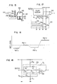
- the signal fed to the proportion electromagnetic device 42 is a duty pulse signal the duration of which is controlled, and this duty pulse signal is formed by a circuit shown in Fig. 3, which is a part of the computer 72.
- a comparator 88 has its inverting input terminal to which is applied a signal from the heat-type flow sensor 32, and its non-inverting input terminal to which is applied a level signal from a level setting circuit 90 a signal from a comparator 88 is fed to a duty pulse generating circuit 92 at the following stage, where it is converted to a duty pulse which is then fed to the proportion electromagnetic device 42.
- the signal from the heat-type flow sensor 32 for example, as shown in Fig. 4 (a) by H/W, is applied to the inverting input terminal of the comparator 88, it is compared with a level R ef applied from the level setting circuit 90 to the non-inverting input terminal.
- the compared result is a pulse signal as shown in Fig. 4(b).
- This pulse signal acts to drive a transistor within the duty pulse generating circuit 92 so as to produce the duty pulse therefrom.
- This duty pulse as described above, is applied to the proportion electromagnetic device 42, which then drives the air-scaling valve 38 so that the output of the heat-type flow sensor 32 approaches the level Rer. That is, the time, T c as shown in Fig. 4(b) is given for closing of the air-scaling valve 38 and the time To as shown for opening of the valve 38.
- the proportion electromagnetic device 42 can control the air-scaling valve 38 so that the output signal from the heat-type flow sensor 32 becomes constant.
- the level setting circuit 90 can change the reference level in accordance with the operating condition of the engine, for example with the signals from the water temperature sensor 74, revolution rate sensor 76, throttle valve open sensor 78, oxygen sensor 80, and so on.
- the comparator 88 supplies the H/W signal of much time To in Fig. 4, to the duty pulse generating circuit 92.
- the computer 72 including the duty pulse generating circuit 92 supplies the duty pulse to the proportion electromagnetic device 42 thereby pushing the air-scaling valve 38 downward in Fig. 1 so that the amount of air flow in the air-scaling portion such amount is determined by the air-scaling valve 38 and air-scaling orifice 36 reaches the setting level R ef .
- the moving core 62 of the proportion electromagnetic device 42 causes the fuel-scaling valve 50 to move in the same direction as does the air-scaling valve 38, the fuel flow in the fuel-scaling portion which is determined by the fuel-scaling valve 50 and fuel-scaling orifice 48 in naturally decreased with the decrease of air flow of the engine.
- the fuel passing the fuel-scaling valve 50 is injected into the air-intake path 12 from the fuel injection portion 44.
- the fuel injection flow from the fuel injection portion 44 is continuous.
- the shape of the fuel-scaling valve 50 must be determined so that the air/fuel ratio at this time approaches a target value, for example, a theoretical air/fuel ratio.
- the Venturi negative pressure at the Venturi portion 28 increases and as a result much air is flowed through the bypass 30.
- the signal H/W from the heat-type flow sensor 32 becomes higher than the setting level R e , as indicated by region III in Fig. 4(b).
- the comparator 88 supplies the signal H/W of much time T c as shown in Fig. 4(b) to the duty pulse generating circuit 92.
- the computer 72 thus supplies the duty pulse to the proportion electromagnetic device 42 which then drives the air-scaling valve 38 to move upward in Fig.
- the movable core 62 of the proportion electromagnetic device 42 also drives the fuel-scaling valve 50 to move in the same direction as does the air-scaling valve 38, the fuel passing the fuel-scaling portion, determined by the fuel-scaling valve 50 and fuel-scaling orifice 48 is naturally increased in accordance with the increase of air flow to the engine.
- the fuel passing the fuel-scaling valve 50 is injected as a continuous flow from the fuel injection portion 44 into the air-intake path 12.
- the shape of the fuel-scaling valve 50 is determined so that the air/fuel ratio at this time approaches to a target value as set forth above.
- the proportion electromagnetic device 42 is kept at the condition and thus the fuel-scaling portion formed of the fuel-scaling valve 50 and fuel-scaling orifice 48 is considered to be substantially a fixed orifice.
- the shape of the fuel-scaling valve 50 is determined so that the air-fuel ratio approaches to a theoretical value.
- the fuel injection portion continuously supplies fuel into the air-intake path at the meeting portion of the air-intake tubes, the mixture of air and fuel can-be kept uniform in the space between the air-intake path and the meeting portion of the air-intake tubes.
- the precision of the air flow meter may be relatively low, and a signal processing circuit to be connected to the air flow meter can be simplified in its construction.
- the air-scaling valve attenuates the air-intake pulsation to prevent the air flow meter from undergoing the air-intake pulsation.
- the electromagnetic device 24, valve 26, orifice 22 and correction air path 20 has a function of controlling the revolution rate of idle.
- the computer 72 has stored therein a target revolution rate of idle associated with the temperature of cooling water for engine, and an actual rotation rate of idle is compared with this target idle revolution rate a control signal based on the resulting deviation therebetween being applied to the electromagnetic device 24 so as to change the amount of air flow in the correction air path 20 with the result that the actual idle rotation rate converges the target idle rotation rate.
- the actual idle rotation rate can be controlled to be a value suitable for the temperature of engine.
- the signals from the water temperature sensor 74 and the rotation rate sensor 76 are stored in the computer 72 and properly processed to produce a control signal.
- FIG. 5 shows an accelerating device for increasing the amount of fuel supply for smooth acceleration of the engine.
- An accelerating device 94 is formed of a push rod 96 positioned on the same axis of the fuel-scaling valve 50, a diaphragm 98 fixing the push rod 96, a first pressure chamber 100 formed by the diaphragm 98 and the main body 10, a second pressure chamber 104 formed by the diaphragm 98 and the cover 102, a first compression spring 106 disposed in the first pressure chamber 100, a second compression spring 108 disposed in the second pressure chamber 104, a first signal path 110 for connecting the first pressure chamber, the second pressure chamber 104-and the air-intake path 12, a second signal path 112, and a seal hollow type diaphragm for isolating the first pressure chamber 100 from the fuel path 46.
- the second signal path 112 has a wider diameter than the first signal path 100.
- the pressures in the first and second pressure chambers 100 and 104 are equal, and the push rod 96 is determined in its position by the balance of the forces which the first and second compression springs 106 and 108 exert.
- the throttle valve 18 When the throttle valve 18 is rapidly opened for acceleration of engine, the pressure on the downstream side of the throttle valve 18 approaches the atmospheric pressure and transmitted through the first and second signal paths 110 and 112 to the first and second pressure chambers 100 and 104.
- the first signal path 110 has a smaller diameter than the second signal path 112
- the first pressure chamber 100 has a pressure changed as indicated by one-dot chain line A in Fig. 6 and the second pressure chamber 104 has a pressure changed as indicated by solid line B in Fig. 6.
- FIG. 8 shows another embodiment of the accelerating device.
- An accelerating device 116 is formed of a diaphragm 120 held between the main body 10 and a cover 118, an operating pressure chamber 122 formed by the diaphragm 120 and the cover 118, a compression spring 124 provided in the operating pressure chamber 122, a pressure path 126 for transmitting the pressure at the downstream side of the throttle valve 18 to the operating pressure chamber 122, a pump chamber 128 formed by the diaphragm 120 and the main body 10, a fuel introducing path 130 for connecting the pump chamber 128 and the fuel path 46 on the upstream side of the fuel-scaling orifice 48, a check valve 132 provided in the fuel introducing path 130 to allow fuel to flow to the pump chamber 128, a fuel leading-out path 136 for connecting the pump chamber 128 and an acceleration nozzle 134 opening toward the air-intake path 12, and a check valve 138 provided in the fuel leading-out path 136 to allow fuel to flow only to the acceleration nozzle 134.
- the pump chamber 128 Before the engine is accelerated, the pump chamber 128 has fuel loaded. At this time, the operating pressure chamber 122 is at a negative pressure and thus the compression spring 124 is bet. When the throttle valve 18 is opened for acceleration of engine, the operating pressure chamber 122 has a pressure close to the atmospheric pressure, and the compression spring 124 forces the diaphragm 120 to move to the right in Fig. 8, thereby causing the fuel within the pump chamber 128 to inject from the acceleration nozzle 134 into the air-intake path 12 via the fuel leading-out path 136. Thus, upon acceleration, fuel supply can be increased temporarily.
- a decelerating device 140 is formed of a fuel cut-off electromagnetic valve 142 and a seat portion 144. This seat portion 144 is provided in a path 46A for connecting the fuel-scaling valve 50 and the pressure regulator 70.
- the fuel cut-off electromagnetic valve 142 closes the seat portion 144, stopping the fuel from injection from the fuel injecting portion 44.
- the stopping of fuel supply upon deceleration of engine can greatly contribute to the decrease of harmful components within. the exhaust gas.
- the signal to the fuel cut-off electromagnetic valve 142 is supplied from the computer 72 when the throttle valve 18 is opened to a degree for idle and the revolution rate of the engine is higher than the rotation rate of idle.
- the input to the computer 72 is the signals from the rotation rate sensor 76, and the opening degree sensor 78.
- a start nozzle 146 opens into the air-intake path on the downstream side of the throttle valve 18 and the start fuel nozzle 146 communicates with the fuel path 46 on the upstream of the fuel-scaling orifice 48 via a start fuel path 148.
- An electromagnetic fuel control valve 150 is provided in the start fuel path 148.
- the fuel-scaling valve 50 and the fuel-scaling orifice 48 are operated to scale fuel and the fuel is supplied from the fuel injection portion 44.
- the fuel control valve 150 opens to permit start increment fuel to be supplied via the start fuel path 148 from the start nozzle 146, thereby making the engine start in good condition.
- the signal to be transmitted to the electromagnetic fuel control valve 150 is of course supplied from the computer 72, and it is generated when the throttle valve 18 is opened to a degree for idle and when the temperature of engine is lower than a predetermined value.
- the computer 72 is supplied with the signals from the opening degree sensor 78 and the water temperature sensor 76.
- the start nozzle 146 can also be used as an acceleration increment nozzle in which case the electromagnetic fuel control valve 150 may be opened upon acceleration.
- the computer 72 detects the opening speed signal from the opening degree sensor 78 to decide the acceleration of the engine.
- an eccentric valve 152 is rotatably mounted in the air-intake path 12 on the upstream side of the fuel injection portion 44.
- This eccentric valve 152 is slightly opened when a small amount of air flow passes in the air intake path 12, and it increases its opening degree as the amount of air flow increases.
- the eccentric valve 152 is slightly opened even if the throttle valve 18 is opened to a great extent, and therefore the air flow speed is high at the peripheral edge of the eccentric valve 152. Consequently, the fuel supplied from the fuel injection portion 44 is vaporized by this air flow at high speed.
- Fig. 12 shows a control mechanism of the eccentric valve 152.
- This eccentric valve 152 is urged to be always closed by a torsion spring (not shown), and a counterlever 156 with a counterweight 154 fixed is fastened to the eccentric valve 152.
- the extent to which the eccentric valve 152 is opened is determined by the balance with the dynamic pressure the air flow exerts on the eccentric valve 152. Thus, if a small amount of air flows in the air-intake path 12 under the condition that the throttle valve 18 is opened to a great extent, the eccentric valve 152 is opened to a small extent.
- eccentric valve 152 can be given the following function.
- a lever 158 fixed to the eccentric valve 152 is connected to a dash po t 160.
- the dash pot 160 has a function that, when the eccentric valve 152 is intended to be rapidly opened, weaken the quick opening operation to a slow operation. Thus, when the throttle valve 18 is opened upon acceleration, the eccentric valve 152 is intended to rapidly open, but the dash pot 160 acts to delay the quick opening operation. As a result, the air flow passing through the peripheral edge of the eccentric valve 152 is increased in its speed, so that the air flow passing around the fuel injection portion 44 is increased in its speed to promote the vaporization of fuel.
- the fuel-scaling valve 50 and the fuel-scaling orifice 48 are required to precisely scale the amount of fuel in the wide range of conditions from the idling drive to high-speed drive as set forth above.
- the pressure regulator 70 which is set to the fuel pressure of 0.7 kg/cm 2 , is provided on the upstream side of the fuel-scaling valve 50 and the fuel-scaling orifice 48, and therefore a pressure difference of about 0.7 kg/cm 2 takes place between the upstream and downstream sides of the fuel-scaling orifice 48.
- the fuel-scaling valve 52 and fuel-scaling orifice 48 must be made with high precision. To solve this problem, devices as shown in Figs. 14 and 15 are employed.
- the first pressure regulator 70 is provided on the upstream side of the fuel-scaling orifice 48.
- This regulator 70 is formed of a diaphragm 162, a compression spring 164, and a pressure regulating valve 166.
- a predetermined pressure or in this example, 0.7 kg/cm 2
- the fuel is escaped from the pressure regulating valve 166 to the fuel tank 66, so as to be kept at a certain pressure.
- a second pressure regulator 168 is provided on the downstream side of the fuel-scaling orifice 148, and it is formed of a diaphragm 170.
- a compression spring 172, and a pressure regulating valve 174 are examples of a pressure regulating valve 174.
- the pressure regulating valve 174 opens when the fuel pressure is 0.6 kg/cm 2 , to send the fuel to the fuel injection portion 44.
- a pressure difference between the first and second pressure regulators 70 and 168 is as low as 0.1 kg/cm 2 , so that fuel flow can be scaled precisely with the precision of the fuel-scaling valve 50 and fuel-scaling orifice 48 being not so increased.
- the device of Fig. 15 employs an orifice 176 in place of the second pressure regulator 168.
- This orifice 176 can also reduce the pressure difference between the upstream and downstream sides of the fuel-scaling orifice 48.
- the above-described correcting devices are mechanical devices. Description will be made of an electrical device for changing a signal to be fed to the proportion electromagnetic device 42.
- Fig. 16 shows a method of increasing or decreasing (inclusive of cut-off) the amount of fuel by changing the set level in accordance with the drive condition.
- the set level is made as R ef-s lower than the normal drive set level Ref. n .
- Lowering of set level increases the time-T c component as shown in Fig. 4(b), and thus the proportion electromagnetic device 42 drives the air-scaling valve 38 to decrease the amount of air passing through the bypass 30.
- the fuel-scaling valve 50 is moved to increase the amount of fuel. Consequently, the fuel amount can be increased upon starting.
- the proportion electromagnetic scaling valve 42 drives the air-scaling valve 38 to decrease the amount of air passing through the bypass 30 and thus the amount of fuel passing through the fuel-scaling valve 50 is increased.
- the set level is increased to Ref a larger than the Ref-n at the normal drive.
- Increase of set level increases the time-To components as shown in Fig. 4(b), and thus, the proportion electromagnetic device 42 drives the air-scaling valve 38 to increase the amount of air passing through the bypass 30.
- the fuel-scaling valve 50 is moved to decrease the amount of fuel, thereby enabling the fuel upon decelerating to be decreased to a small amount or to be cut off.
- Such a correction can be performed by a circuit as shown in Fig. 17.
- the level setting circuit 90 is formed of parallel connected resistors R 1 to R 4 and transistors TR, to TR 4 .
- the values of the resistors R 1 , R 2 , R 3 and R 4 are selected as R,>R 2 >R 3 >R 4 , and the value of the resistor R 2 is a set level Ref. n at the normal drive time, the value of the resistor R 1 is a set level R ef - d at the decelerating time, that of resistor R 3 is a set level Ref. a at the accelerating time, and that of the resistor R 4 is a set level Ref. at the starting time.
- each of these resistors R 1 to R 4 is connected in the circuit at the corresponding drive time by turning on the associated one of the transistors TR 1 to TR 4 , the set level can be determined.
- the turning-on of the transistors TR, to TR 4 is controlled by the computer 72.
- a gain control circuit 178 is provided between the inverting input terminal of the comparator 88 and heat-type flow sensor 32.
- the gain control circuit 178 is formed of parallel-connected resistors R 5 to R 7 between the heat-type flow sensor 32 and comparator 88, and diodes d 1 and d 2 respectively connected in series with the resistors R s and R 7 (the diodes connected reversely in their polarity).
- a resistor R 8 is for setting level, Rg for shunting the output and inverting input terminals of the comparator 88, and R 10 and R 11 for setting gain switching voltages.
- the gain, G determined by the resistors R s to R 7 and the resistor Rg is given by the following expression:
- the fuel injection device is more improved.
Landscapes
- Engineering & Computer Science (AREA)
- Chemical & Material Sciences (AREA)
- Combustion & Propulsion (AREA)
- Mechanical Engineering (AREA)
- General Engineering & Computer Science (AREA)
- Physics & Mathematics (AREA)
- Fluid Mechanics (AREA)
- General Physics & Mathematics (AREA)
- Analytical Chemistry (AREA)
- Electrical Control Of Air Or Fuel Supplied To Internal-Combustion Engine (AREA)
- Fuel-Injection Apparatus (AREA)
Claims (20)
Applications Claiming Priority (18)
| Application Number | Priority Date | Filing Date | Title |
|---|---|---|---|
| JP18850080A JPS57113927A (en) | 1980-12-29 | 1980-12-29 | Fuel control device |
| JP188501/80 | 1980-12-29 | ||
| JP18849780A JPS57113958A (en) | 1980-12-29 | 1980-12-29 | Fuel controller |
| JP188500/80 | 1980-12-29 | ||
| JP188496/80 | 1980-12-29 | ||
| JP188497/80 | 1980-12-29 | ||
| JP188498/80 | 1980-12-29 | ||
| JP18849480A JPS57113956A (en) | 1980-12-29 | 1980-12-29 | Fuel control device |
| JP18849680A JPS57113951A (en) | 1980-12-29 | 1980-12-29 | Fuel control device |
| JP55188498A JPS57113926A (en) | 1980-12-29 | 1980-12-29 | Fuel control device |
| JP18849980A JPS57113959A (en) | 1980-12-29 | 1980-12-29 | Fuel controller |
| JP188494/80 | 1980-12-29 | ||
| JP188495/80 | 1980-12-29 | ||
| JP188502/80 | 1980-12-29 | ||
| JP18849580A JPS57113957A (en) | 1980-12-29 | 1980-12-29 | Fuel controller |
| JP55188501A JPS57113960A (en) | 1980-12-29 | 1980-12-29 | Fuel controller |
| JP18850280A JPS57113961A (en) | 1980-12-29 | 1980-12-29 | Fuel controller |
| JP188499/80 | 1980-12-29 |
Publications (3)
| Publication Number | Publication Date |
|---|---|
| EP0055482A2 EP0055482A2 (de) | 1982-07-07 |
| EP0055482A3 EP0055482A3 (en) | 1983-10-05 |
| EP0055482B1 true EP0055482B1 (de) | 1986-04-02 |
Family
ID=27577570
Family Applications (1)
| Application Number | Title | Priority Date | Filing Date |
|---|---|---|---|
| EP81110799A Expired EP0055482B1 (de) | 1980-12-29 | 1981-12-28 | Kraftstoffeinspritzvorrichtung für Brennkraftmaschine mit innerer Verbrennung |
Country Status (4)
| Country | Link |
|---|---|
| US (1) | US4442818A (de) |
| EP (1) | EP0055482B1 (de) |
| KR (1) | KR830008026A (de) |
| DE (1) | DE3174279D1 (de) |
Families Citing this family (16)
| Publication number | Priority date | Publication date | Assignee | Title |
|---|---|---|---|---|
| JPS57153755U (de) * | 1981-03-25 | 1982-09-27 | ||
| JPS57193760A (en) * | 1981-05-22 | 1982-11-29 | Hitachi Ltd | Fuel controller |
| JPS5896163A (ja) * | 1981-12-02 | 1983-06-08 | Hitachi Ltd | 燃料制御装置 |
| JPS58138258A (ja) * | 1982-02-10 | 1983-08-17 | Hitachi Ltd | 燃料供給装置 |
| JPS58185948A (ja) * | 1982-04-26 | 1983-10-29 | Hitachi Ltd | 燃料噴射制御装置 |
| JPS5970853A (ja) * | 1982-10-18 | 1984-04-21 | Hitachi Ltd | 自動車用エンジンの制御装置 |
| US4579097A (en) * | 1983-07-18 | 1986-04-01 | Nissan Motor Company, Limited | Fuel supply apparatus and method for internal combustion engines |
| JPH0733781B2 (ja) * | 1983-08-26 | 1995-04-12 | 株式会社日立製作所 | エンジン制御装置 |
| JPS60145438A (ja) * | 1983-09-07 | 1985-07-31 | Hitachi Ltd | 内燃機関の燃料制御装置 |
| JPS60138245A (ja) * | 1983-12-26 | 1985-07-22 | Toyota Motor Corp | エンジンの燃料噴射制御装置 |
| US4498440A (en) * | 1984-04-02 | 1985-02-12 | Honda Giken Kogyo Kabushiki Kaisha | Mixture control apparatus for carburetor |
| US4674460A (en) * | 1985-09-30 | 1987-06-23 | Chrysler Motors Corporation | Fuel injection system |
| JPS62240452A (ja) * | 1986-04-09 | 1987-10-21 | Hitachi Ltd | 燃料制御装置 |
| KR950009044B1 (ko) * | 1987-06-17 | 1995-08-14 | 가부시키가이샤 히타치세이사쿠쇼 | 발열저항식 공기유량측정장치 |
| JP3794474B2 (ja) * | 2001-10-19 | 2006-07-05 | 本田技研工業株式会社 | キャブレタの燃料供給規制装置 |
| GB2432411B (en) * | 2005-11-16 | 2011-02-16 | L E Jackson | Refrigeration beam and refrigeration apparatus incorporating the same |
Family Cites Families (9)
| Publication number | Priority date | Publication date | Assignee | Title |
|---|---|---|---|---|
| DE2063963A1 (de) * | 1970-12-28 | 1972-07-20 | Bosch Gmbh Robert | Kraftstoffeinspritzanlage für gemischverdichtende, fremdgezündete Brennkraftmaschinen |
| JPS5118023B2 (de) * | 1972-04-14 | 1976-06-07 | ||
| JPS5924264B2 (ja) * | 1975-02-27 | 1984-06-08 | カブシキガイシヤ ニツポンジドウシヤブヒンソウゴウケンキユウシヨ | 気化器の空燃比調整装置 |
| JPS52114826A (en) * | 1976-03-22 | 1977-09-27 | Toyota Motor Corp | Feedback type electronic controller for a fuel injection type internal combustion engine |
| JPS591070Y2 (ja) * | 1977-03-07 | 1984-01-12 | トヨタ自動車株式会社 | 内燃機関の空燃比制御装置 |
| JPS5833385B2 (ja) * | 1977-09-12 | 1983-07-19 | トヨタ自動車株式会社 | 燃料噴射制御装置 |
| JPS6047462B2 (ja) * | 1978-06-02 | 1985-10-22 | 株式会社日立製作所 | 電子制御燃料噴射装置の吸入空気量計測装置 |
| JPS55148927A (en) * | 1979-05-09 | 1980-11-19 | Hitachi Ltd | Air-fuel ratio controller |
| JPS5696138A (en) * | 1979-12-28 | 1981-08-04 | Hitachi Ltd | Air/fuel ratio controller |
-
1981
- 1981-12-22 US US06/333,296 patent/US4442818A/en not_active Expired - Fee Related
- 1981-12-28 DE DE8181110799T patent/DE3174279D1/de not_active Expired
- 1981-12-28 EP EP81110799A patent/EP0055482B1/de not_active Expired
- 1981-12-28 KR KR1019810005268A patent/KR830008026A/ko not_active Ceased
Also Published As
| Publication number | Publication date |
|---|---|
| EP0055482A2 (de) | 1982-07-07 |
| EP0055482A3 (en) | 1983-10-05 |
| US4442818A (en) | 1984-04-17 |
| DE3174279D1 (en) | 1986-05-07 |
| KR830008026A (ko) | 1983-11-09 |
Similar Documents
| Publication | Publication Date | Title |
|---|---|---|
| US4442818A (en) | Fuel injection apparatus for internal combustion engines | |
| KR880002075B1 (ko) | 스파아크 점화 내연기관용 전자(電子)조절식 연료 분사장치 | |
| US4524745A (en) | Electronic control fuel injection system for spark ignition internal combustion engine | |
| US3963009A (en) | Carburation devices for internal combustion engines | |
| US4416239A (en) | Electronic control system for an internal combustion engine with correction means for correcting value determined by the control system with reference to atmospheric air pressure | |
| US4391249A (en) | Method of operating a combustible mixture generator of an internal combustion engine and apparatus for carrying out the method | |
| JPH0218297Y2 (de) | ||
| US4003350A (en) | Fuel injection system | |
| US4333440A (en) | Apparatus for controlling recirculated exhaust gas quantities in self-igniting internal combustion engines | |
| US4425886A (en) | Electronic control apparatus for internal combustion engine | |
| US4579097A (en) | Fuel supply apparatus and method for internal combustion engines | |
| US4380988A (en) | Air/fuel ratio control system for internal combustion engines, having exhaust gas recirculation control function | |
| US4480606A (en) | Intake system of an internal combustion engine | |
| US4096839A (en) | Internal combustion engine air-fuel ratio control system utilizing oxygen sensor | |
| US4111169A (en) | Spark ignition internal combustion engines | |
| CA1155015A (en) | Electronic controlled carburetor | |
| US4375797A (en) | Air/fuel ratio feedback control system for internal combustion engines | |
| US4401080A (en) | Air/fuel ratio control system for internal combustion engines, having air/fuel ratio control function at engine acceleration | |
| US4211201A (en) | Fuel supply apparatus for internal combustion engines | |
| US4052970A (en) | Air-fuel ratio control system utilizing oxygen sensor and pressure differential sensor | |
| US3956433A (en) | Automatic device for equalizing the adjustment of the carburetter to the operation of an engine not yet running at a steady temperature | |
| US3561409A (en) | Auxiliary device for carburetor engines for preparing the fuel condensate | |
| US4462367A (en) | Fuel controller for internal combustion engine | |
| US4572134A (en) | Double carburetor | |
| US4475518A (en) | Fuel injection apparatus for internal combustion engines |
Legal Events
| Date | Code | Title | Description |
|---|---|---|---|
| PUAI | Public reference made under article 153(3) epc to a published international application that has entered the european phase |
Free format text: ORIGINAL CODE: 0009012 |
|
| AK | Designated contracting states |
Designated state(s): BE CH DE FR GB IT NL SE |
|
| PUAL | Search report despatched |
Free format text: ORIGINAL CODE: 0009013 |
|
| AK | Designated contracting states |
Designated state(s): BE CH DE FR GB IT LI NL SE |
|
| 17P | Request for examination filed |
Effective date: 19831010 |
|
| RBV | Designated contracting states (corrected) |
Designated state(s): DE FR GB IT |
|
| GRAA | (expected) grant |
Free format text: ORIGINAL CODE: 0009210 |
|
| AK | Designated contracting states |
Kind code of ref document: B1 Designated state(s): DE FR GB IT |
|
| REF | Corresponds to: |
Ref document number: 3174279 Country of ref document: DE Date of ref document: 19860507 |
|
| ITF | It: translation for a ep patent filed | ||
| ET | Fr: translation filed | ||
| PLBE | No opposition filed within time limit |
Free format text: ORIGINAL CODE: 0009261 |
|
| STAA | Information on the status of an ep patent application or granted ep patent |
Free format text: STATUS: NO OPPOSITION FILED WITHIN TIME LIMIT |
|
| 26N | No opposition filed | ||
| ITTA | It: last paid annual fee | ||
| PGFP | Annual fee paid to national office [announced via postgrant information from national office to epo] |
Ref country code: FR Payment date: 19910917 Year of fee payment: 11 |
|
| PGFP | Annual fee paid to national office [announced via postgrant information from national office to epo] |
Ref country code: GB Payment date: 19910928 Year of fee payment: 11 |
|
| PGFP | Annual fee paid to national office [announced via postgrant information from national office to epo] |
Ref country code: DE Payment date: 19911231 Year of fee payment: 11 |
|
| PG25 | Lapsed in a contracting state [announced via postgrant information from national office to epo] |
Ref country code: GB Effective date: 19921228 |
|
| GBPC | Gb: european patent ceased through non-payment of renewal fee |
Effective date: 19921228 |
|
| PG25 | Lapsed in a contracting state [announced via postgrant information from national office to epo] |
Ref country code: FR Effective date: 19930831 |
|
| PG25 | Lapsed in a contracting state [announced via postgrant information from national office to epo] |
Ref country code: DE Effective date: 19930901 |
|
| REG | Reference to a national code |
Ref country code: FR Ref legal event code: ST |