EP0055598B1 - Pédale pour vélo - Google Patents
Pédale pour vélo Download PDFInfo
- Publication number
- EP0055598B1 EP0055598B1 EP81306067A EP81306067A EP0055598B1 EP 0055598 B1 EP0055598 B1 EP 0055598B1 EP 81306067 A EP81306067 A EP 81306067A EP 81306067 A EP81306067 A EP 81306067A EP 0055598 B1 EP0055598 B1 EP 0055598B1
- Authority
- EP
- European Patent Office
- Prior art keywords
- foot support
- pedal
- foot
- portions
- support portions
- Prior art date
- Legal status (The legal status is an assumption and is not a legal conclusion. Google has not performed a legal analysis and makes no representation as to the accuracy of the status listed.)
- Expired
Links
Images

Classifications
-
- B—PERFORMING OPERATIONS; TRANSPORTING
- B62—LAND VEHICLES FOR TRAVELLING OTHERWISE THAN ON RAILS
- B62M—RIDER PROPULSION OF WHEELED VEHICLES OR SLEDGES; POWERED PROPULSION OF SLEDGES OR SINGLE-TRACK CYCLES; TRANSMISSIONS SPECIALLY ADAPTED FOR SUCH VEHICLES
- B62M3/00—Construction of cranks operated by hand or foot
- B62M3/08—Pedals
-
- Y—GENERAL TAGGING OF NEW TECHNOLOGICAL DEVELOPMENTS; GENERAL TAGGING OF CROSS-SECTIONAL TECHNOLOGIES SPANNING OVER SEVERAL SECTIONS OF THE IPC; TECHNICAL SUBJECTS COVERED BY FORMER USPC CROSS-REFERENCE ART COLLECTIONS [XRACs] AND DIGESTS
- Y10—TECHNICAL SUBJECTS COVERED BY FORMER USPC
- Y10T—TECHNICAL SUBJECTS COVERED BY FORMER US CLASSIFICATION
- Y10T74/00—Machine element or mechanism
- Y10T74/21—Elements
- Y10T74/2164—Cranks and pedals
- Y10T74/2168—Pedals
-
- Y—GENERAL TAGGING OF NEW TECHNOLOGICAL DEVELOPMENTS; GENERAL TAGGING OF CROSS-SECTIONAL TECHNOLOGIES SPANNING OVER SEVERAL SECTIONS OF THE IPC; TECHNICAL SUBJECTS COVERED BY FORMER USPC CROSS-REFERENCE ART COLLECTIONS [XRACs] AND DIGESTS
- Y10—TECHNICAL SUBJECTS COVERED BY FORMER USPC
- Y10T—TECHNICAL SUBJECTS COVERED BY FORMER US CLASSIFICATION
- Y10T74/00—Machine element or mechanism
- Y10T74/21—Elements
- Y10T74/2164—Cranks and pedals
- Y10T74/2168—Pedals
- Y10T74/217—Pedals with toe or shoe clips
Definitions
- This invention relates to a cycle pedal comprising a pedal body having a pedal shaft, said body having an upper surface on which are provided first and second foot support portions.
- pedal bodies for cycle pedals as disclosed for example in United States Patent No. 2,542,548 and Swiss Patent No. 279,819, have foot support portions provided on either side of a pedal shaft and extending parallel thereto.
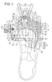
- the foot support portions are disposed to extend rectilinearly parallel to the pedal shaft axis. However, when a cyclist places his foot on the pedal body the heads of the first, second, third, fourth and fifth metatarsi are disposed along an arcuate line, so that when the head of the first metatarsus is placed on the foot support portion, that of the fifth will tend to come out of contact with said support portion.
- the skeleton of the human foot comprises an assembly of 26 bones, which are roughly divided from the point of view of construction, into tarsi, metatarsi, and phalanges.
- the tarsi are composed of seven bones of the calcaneous, talsus, cuboid, navicular, and first to third cuneiforms in a tightly knit combination, the metatarsi comprising five bones corresponding in number to the toes and extending forwardly from the group of tarsal bones and arranged laterally across the foot, the phalanges extending forwardly from the metatarsi and comprising 14 bones with the first phalange of the big toe comprising two bones and the second to fifth phalanges of the other toes each comprising three bones respectively.
- the calcaneous, cuboid, first to third cuneiforms, first and third metatarsi, and first to third phalanges are included in a first group, and the talus, navicular, fourth and fifth metatarsi, and fourth and fifth phalanges, are included in a second group.
- the bones in the first group carry the weight of the body and function to kick the ground when a person steps forward and those in the second group function to balance his body for a smooth walk.
- the conventional pedal creates a problem in that the head of the fifth phalange is not supported by the foot support portion when that of the first phalange is placed thereon, so that the cyclist cannot transmit the downward thrust of his pedalling force effectively -to the pedal body, and his pedalling movement tends to be poorly balanced and not smooth. As a result, it is difficult for him to maximise his pedalling force and obtain an efficient use of energy because his foot becomes tired relatively quickly.
- FR-A-2440867 discloses a cycle pedal comprising a pedal body having a pedal shaft, said body having an upper surface on which are provided first and second foot support portions, said second foot support portion being rearwardly offset with respect to said first foot support portion. These foot support portions are not; how- - ever, able simultaneously properly to support the first and fifth metatarsal head portions. Neither in direct proximity to the pedal shaft axis.
- the present invention provides a cycle pedal comprising a pedal body having a pedal shaft, said body having an upper surface on which are provided first and second foot support portions said second foot support portion being rearwardly offset with respect to said first foot support portion characterized in that said first and second foot support portions are formed and arranged substantially separately from each other to have a surface area sufficient simultaneously to support the head portion of a first metatarsus and at least the head portion of the fifth metatarsus of a cyclist's foot, respectively; at least said second foot support portion being intersected by a plane through the pedal shaft axis and at right angles to the general plane of said foot support portions; and said first and second foot support portions being displaced upwardly from the main pedal body.
- the treading or pedalling force is transmitted effectively to the pedal body through the head portion of the first metatarsus and the downward and return phases of the pedalling action are facilitated. Also, the effective supporting of the head portion of the fifth metatarsus on the second foot support portion enables the cyclist to achieve a well-balanced, smooth, and non-tiring pedalling action with an increased pedalling force.
- the pedal body of the invention enables provision of a sufficient degree of foot support necessary for pedalling with a minimum size of pedal body which as a result is simple in shape, lightweight, and inexpensive to produce.
- the first and second foot support portions may be formed integrally with the pedal body, or provided on a member formed separately from the pedal body.
- the use of such a separate member facilitates the provision of an antiskid means on each foot support portion as well as the manufacture of a pedal having a common pedal body with different first and second foot support portions having various shapes, sizes, or spacings therebetween to suit different individual riders.
- first and second foot support portions each of which has an area large enough to accommodate the head portions of all the metatarsi, may be flush at its upper surface with the pedal body, but preferably projects upwardly from the, upper surface thereof and is provided with looped grooves as an anti-skid means at the upper surface of each said foot support portion.
- Fig. 1 shows a right-hand side pedal having a generally block-shaped pedal body 10 formed of an aluminum alloy by die casting and a generally plate-form foot support member 20 formed separately from the pedal body 10, also by die casting, the foot support member 20 being secured to the pedal body 10.
- the pedal body 10 as viewed in Fig. 1, is generally V-shaped with the base of the V-shape projecting forwardly at a laterally intermediate position and the limbs 11, 12 of the V-shape extending rearwardly at either side.
- a rear side plate 13 formed separately from the body 10 is fixed with the aid of screws or the like.
- a tubular portion 16 having a threaded bore is provided at one side (the left side in the drawing) of the pedal body 10 and screw-threadedly engaged with a threaded pedal shaft 17 as shown in Fig. 2.
- a bearing cylinder 18 is rotatably supported on the outer peripheries of the tubular member 16 and the pedal shaft 17 via ball bearings 19.
- the bearing cylinder 18 is provided at its outer periphery with a screw threaded portion 18a for screw threaded engagement with a crank arm (not shown) to rotatably support the pedal body 10 on the crank arm.
- the foot support member 20 is fixed to the upper surface of the pedal body 10 with the aid of fixing means, such as screws or bolts, and is provided with a first foot support portion 21 for supporting the head portion T 1 of a first metatarsus K 1 of a cyclist's foot and a second foot support portion 22 for supporting at least the head T 5 of a fifth metatarsus Ks of the second to fifth metatarsi K 2 to K s , so that, when the first metatarsus head portion T 1 contacts the first foot support portion 21, at least the head portion T s of the fifth metatarsus K s is automatically brought into contact with the second foot support portion 22.
- the second foot support portion 22, as shown in Fig. 1 desirably has a sufficient area to accommodate the head portions T 3 to T 5 of the third to fifth metatarsi K 3 to K 5 .
- first and second foot support portions 21 and 22 could be formed with a sufficiently large area to accommodate the head portions T 2 to 7 s of the second to fifth metatarsi K 2 to K s , or to contact only the head portion T s of the firth metatarsus K s , and may if desired be provided directly on the upper surface of the body 10 instead of on a separate support member.
- the first and second foot support portions 21 and 22 are wide enough to support the head of each metatarsal bone of the cyclist's foot and project upwardly of the upper surfaces of the pedal body 10.
- a plurality of grooves 23 and 24 is provided in the upper surfaces of the foot support portions 21 and 22 and extend, for example, longitudinally and bilaterally of the body 10, so that the edges of grooves 23 and 24 serve to prevent the cyclist's foot from skidding.
- the use of grooves 23 and 24, which are looped longitudinally and bilaterally, is even more effective in preventing skidding in any direction.
- first and second foot support portions 21 and 22 are disposed in the vicinity of the longitudinal axis X-X of the pedal shaft 17 and the greater part of each foot bearing portion 21 or 22 is positioned to the front of the axis X-X, the remainder being to the rear thereof.
- the embodiment shown in the drawings has in fact also an auxiliary foot support surface 40 extending rearwardly from the rear side plate 13.
- the auxiliary foot support surface 40 when the head portions of the metatarsi press on the first and second foot bearing portions 21 and 22 respectively, supports the third to fifth metatarsi at the tarsal bone and portions thereof, thereby also transmitting a larger treading force to the auxiliary foot support surface 40.
- the drawings also show a toe clip 50 supported in front of a laterally intermediate portion of the pedal body 10 provided with a toe strap extending across the rear ends of the pedal body limbs 11, 12, the toe clip 50 being supported at its root so as to be longitudinally displaceable relative to the pedal body 10, being clamped between the pedal body 10 and the foot support member 20 with the aid of the fixing means 30, and connected at its other, free, end with an intermediate portion of the toe strap 51.
- a pedal of the present invention is provided with the first and second foot support portions 21 and 22 as described above so that the pedalling force is effectively transmitted to the pedal body 10 from the head portions of the first and at least the fifth metatarsi, whereby the cyclist can improve the efficiency of transmission of the pedalling force, achieve a smooth, well balanced, and non-tiring pedalling action and increase his effective pedalling force.
Landscapes
- Engineering & Computer Science (AREA)
- Chemical & Material Sciences (AREA)
- Combustion & Propulsion (AREA)
- Transportation (AREA)
- Mechanical Engineering (AREA)
- Mechanical Control Devices (AREA)
Claims (7)
Applications Claiming Priority (4)
| Application Number | Priority Date | Filing Date | Title |
|---|---|---|---|
| JP188818/80U | 1980-12-28 | ||
| JP18881880U JPS57111695U (fr) | 1980-12-28 | 1980-12-28 | |
| JP16316181U JPS57133489U (fr) | 1981-10-30 | 1981-10-30 | |
| JP163161/81U | 1981-10-30 |
Publications (2)
| Publication Number | Publication Date |
|---|---|
| EP0055598A1 EP0055598A1 (fr) | 1982-07-07 |
| EP0055598B1 true EP0055598B1 (fr) | 1987-06-03 |
Family
ID=26488699
Family Applications (1)
| Application Number | Title | Priority Date | Filing Date |
|---|---|---|---|
| EP81306067A Expired EP0055598B1 (fr) | 1980-12-28 | 1981-12-23 | Pédale pour vélo |
Country Status (3)
| Country | Link |
|---|---|
| US (1) | US4569249A (fr) |
| EP (1) | EP0055598B1 (fr) |
| DE (1) | DE3176232D1 (fr) |
Families Citing this family (4)
| Publication number | Priority date | Publication date | Assignee | Title |
|---|---|---|---|---|
| US5992266A (en) | 1996-09-03 | 1999-11-30 | Jonathan R. Heim | Clipless bicycle pedal |
| AT410201B (de) * | 2001-06-18 | 2003-03-25 | Hilber Gerhard Ing | Pedal für ein fahrrad |
| FR2846724B1 (fr) * | 2002-11-06 | 2005-07-22 | Michel Garnier | Amelioration du pedalier de bicyclette par l'adoption d'un excentrique dont le manchon est solidaire de la pedeale. |
| FR2880863B1 (fr) * | 2005-01-18 | 2007-03-30 | Michel Garnier | Pedalier de bicyclette pour harmoniser le pedalage du cycliste |
Family Cites Families (11)
| Publication number | Priority date | Publication date | Assignee | Title |
|---|---|---|---|---|
| BE511650A (fr) * | ||||
| US2178921A (en) * | 1938-03-03 | 1939-11-07 | Frank W Schwinn | Pedal |
| US2542548A (en) * | 1943-08-24 | 1951-02-20 | Matthias Eugen | Pedal on a crank drive, especially for bicycles |
| CH256750A (de) * | 1945-07-09 | 1948-08-31 | Ohno Wilhelm | Drehkurbel mit Pedal, insbesondere für Fahrräder und stationäre Antriebsvorrichtungen für elektrische Stromerzeuger. |
| CH279819A (de) * | 1949-12-23 | 1951-12-15 | Matthias Eugen Dr Prof | Pedalantrieb für Fahrräder. |
| CH290481A (de) * | 1951-06-14 | 1953-04-30 | Gruber Georg | Fahrradpedal. |
| ES403352A1 (es) * | 1971-06-19 | 1975-04-16 | Uccellini | Dispositivo para fijar una zapatilla de ciclista al pedal de una bicicleta. |
| DE2938126A1 (de) * | 1978-09-22 | 1980-04-17 | Shimano Industrial Co | Fahrradpedale |
| JPS5743745Y2 (fr) * | 1978-11-11 | 1982-09-27 | ||
| JPS577588Y2 (fr) * | 1978-11-11 | 1982-02-13 | ||
| JPS5571989A (en) * | 1978-11-24 | 1980-05-30 | Mitsubishi Heavy Ind Ltd | Reactor structure |
-
1981
- 1981-12-23 EP EP81306067A patent/EP0055598B1/fr not_active Expired
- 1981-12-23 DE DE8181306067T patent/DE3176232D1/de not_active Expired
-
1984
- 1984-06-06 US US06/617,839 patent/US4569249A/en not_active Expired - Fee Related
Also Published As
| Publication number | Publication date |
|---|---|
| US4569249A (en) | 1986-02-11 |
| DE3176232D1 (en) | 1987-07-09 |
| EP0055598A1 (fr) | 1982-07-07 |
Similar Documents
| Publication | Publication Date | Title |
|---|---|---|
| EP0055597B1 (fr) | Pédale pour vélo ayant des supports principaux et auxiliaires | |
| EP0485956B1 (fr) | Pédale de bicyclette avec deux surfaces pour la fixation d'une platine | |
| US4361972A (en) | Rider's shoe | |
| US5115692A (en) | Bicycle pedal | |
| US4188737A (en) | Sport shoes | |
| EP0811330A3 (fr) | Chaussure avec semelle à contour naturel | |
| US4445397A (en) | Foot conforming pedal for a bicycle | |
| US4893523A (en) | Bicycle and pedal system | |
| GB2239780A (en) | Cycling shoe | |
| ES2121582T3 (es) | Suela de calzado para ciclismo destinada a estar equipada con una cuña. | |
| EP0953499A3 (fr) | Structure de repose-pieds pour véhicule du type scooter | |
| EP0785126B1 (fr) | Dispositif pour une pédale de bicyclette sans cale-pied | |
| JPH05124566A (ja) | 自転車ペダル構造体 | |
| EP0055598A1 (fr) | Pédale pour vélo | |
| WO2006014048A1 (fr) | Processus pour le raffinage de trifluorure d'azote gazeux utilisant un zéolite échangé de métal terreux alcalin | |
| US4526059A (en) | Pedal for a bicycle | |
| US4004468A (en) | Two-position pedal for bicycles | |
| WO2016168122A1 (fr) | Pédale de bicyclette | |
| EP1803638B1 (fr) | Pédale pour bicyclette | |
| JP7100186B1 (ja) | 自転車用ペダル | |
| JPS6237838Y2 (fr) | ||
| GB2343870A (en) | Cycle, scooter or exercise machine | |
| JPH0214554Y2 (fr) | ||
| GB2239779A (en) | cycling shoe | |
| WO1995018551A1 (fr) | Chaussure pour cycliste |
Legal Events
| Date | Code | Title | Description |
|---|---|---|---|
| PUAI | Public reference made under article 153(3) epc to a published international application that has entered the european phase |
Free format text: ORIGINAL CODE: 0009012 |
|
| AK | Designated contracting states |
Designated state(s): BE DE FR GB IT |
|
| 17P | Request for examination filed |
Effective date: 19820803 |
|
| GRAA | (expected) grant |
Free format text: ORIGINAL CODE: 0009210 |
|
| AK | Designated contracting states |
Kind code of ref document: B1 Designated state(s): BE DE FR GB IT |
|
| PG25 | Lapsed in a contracting state [announced via postgrant information from national office to epo] |
Ref country code: IT Free format text: LAPSE BECAUSE OF FAILURE TO SUBMIT A TRANSLATION OF THE DESCRIPTION OR TO PAY THE FEE WITHIN THE PRESCRIBED TIME-LIMIT;WARNING: LAPSES OF ITALIAN PATENTS WITH EFFECTIVE DATE BEFORE 2007 MAY HAVE OCCURRED AT ANY TIME BEFORE 2007. THE CORRECT EFFECTIVE DATE MAY BE DIFFERENT FROM THE ONE RECORDED. Effective date: 19870603 Ref country code: FR Free format text: THE PATENT HAS BEEN ANNULLED BY A DECISION OF A NATIONAL AUTHORITY Effective date: 19870603 Ref country code: BE Effective date: 19870603 |
|
| REF | Corresponds to: |
Ref document number: 3176232 Country of ref document: DE Date of ref document: 19870709 |
|
| EN | Fr: translation not filed | ||
| PLBE | No opposition filed within time limit |
Free format text: ORIGINAL CODE: 0009261 |
|
| STAA | Information on the status of an ep patent application or granted ep patent |
Free format text: STATUS: NO OPPOSITION FILED WITHIN TIME LIMIT |
|
| 26N | No opposition filed | ||
| GBPC | Gb: european patent ceased through non-payment of renewal fee | ||
| PG25 | Lapsed in a contracting state [announced via postgrant information from national office to epo] |
Ref country code: GB Free format text: LAPSE BECAUSE OF NON-PAYMENT OF DUE FEES Effective date: 19881121 |
|
| PGFP | Annual fee paid to national office [announced via postgrant information from national office to epo] |
Ref country code: DE Payment date: 19890131 Year of fee payment: 8 |
|
| PG25 | Lapsed in a contracting state [announced via postgrant information from national office to epo] |
Ref country code: DE Effective date: 19900901 |