EP0055642A1 - Luftgefüllte Triplateleitung für den Hochfrequenzbereich und ihre Anwendungen - Google Patents
Luftgefüllte Triplateleitung für den Hochfrequenzbereich und ihre Anwendungen Download PDFInfo
- Publication number
- EP0055642A1 EP0055642A1 EP81401892A EP81401892A EP0055642A1 EP 0055642 A1 EP0055642 A1 EP 0055642A1 EP 81401892 A EP81401892 A EP 81401892A EP 81401892 A EP81401892 A EP 81401892A EP 0055642 A1 EP0055642 A1 EP 0055642A1
- Authority
- EP
- European Patent Office
- Prior art keywords
- line according
- conductive
- block
- plates
- support
- Prior art date
- Legal status (The legal status is an assumption and is not a legal conclusion. Google has not performed a legal analysis and makes no representation as to the accuracy of the status listed.)
- Granted
Links
- 230000005540 biological transmission Effects 0.000 title claims abstract description 16
- 239000003989 dielectric material Substances 0.000 claims abstract description 9
- 239000002184 metal Substances 0.000 claims description 6
- 229910052751 metal Inorganic materials 0.000 claims description 6
- 230000000295 complement effect Effects 0.000 claims description 4
- 238000005520 cutting process Methods 0.000 claims description 4
- 239000000126 substance Substances 0.000 claims description 4
- 239000004721 Polyphenylene oxide Substances 0.000 claims description 2
- 239000006260 foam Substances 0.000 claims description 2
- 229920006380 polyphenylene oxide Polymers 0.000 claims description 2
- 229920005989 resin Polymers 0.000 claims description 2
- 239000011347 resin Substances 0.000 claims description 2
- 125000006850 spacer group Chemical group 0.000 claims description 2
- 238000003466 welding Methods 0.000 claims description 2
- 238000004519 manufacturing process Methods 0.000 description 6
- 239000004809 Teflon Substances 0.000 description 2
- 229920006362 Teflon® Polymers 0.000 description 2
- 239000000463 material Substances 0.000 description 2
- 238000000465 moulding Methods 0.000 description 2
- RYGMFSIKBFXOCR-UHFFFAOYSA-N Copper Chemical compound [Cu] RYGMFSIKBFXOCR-UHFFFAOYSA-N 0.000 description 1
- HCHKCACWOHOZIP-UHFFFAOYSA-N Zinc Chemical compound [Zn] HCHKCACWOHOZIP-UHFFFAOYSA-N 0.000 description 1
- 238000004026 adhesive bonding Methods 0.000 description 1
- 229910052802 copper Inorganic materials 0.000 description 1
- 239000010949 copper Substances 0.000 description 1
- 230000005684 electric field Effects 0.000 description 1
- 238000003754 machining Methods 0.000 description 1
- 238000001465 metallisation Methods 0.000 description 1
- 239000011701 zinc Substances 0.000 description 1
- 229910052725 zinc Inorganic materials 0.000 description 1
Images

Classifications
-
- H—ELECTRICITY
- H01—ELECTRIC ELEMENTS
- H01P—WAVEGUIDES; RESONATORS, LINES, OR OTHER DEVICES OF THE WAVEGUIDE TYPE
- H01P3/00—Waveguides; Transmission lines of the waveguide type
- H01P3/02—Waveguides; Transmission lines of the waveguide type with two longitudinal conductors
- H01P3/08—Microstrips; Strip lines
- H01P3/085—Triplate lines
Definitions
- the present invention relates generally to transmission lines of electromagnetic waves, and relates more particularly to a transmission line of the air triple plate type operating at microwave frequency.
- a line of the air triplate type comprises two parallel conductive plates, distant from each other, and electrically connected to each other, the space separating these two plates being filled with air serving as a dielectric, and a central conductive tape interposed between and parallel to the two plates.
- the microwave lines of the triplate type usually produced all involve a plate of dielectric material arranged between the two conductive planes.
- one of these known triplate lines comprises a plate forming a support of dielectric material, such as for example glass-teflon, interposed between the two conductive plates, and on which is disposed, for example by photoengraving, the central conductive tape .
- said support plate is held in place by means of a plurality of metal pillars arranged in alignment on either side of the conductive tape, and mounted two by two by superposition between said tape and the two conductive plates. , respectively.
- the object of the present invention is to remedy these drawbacks by proposing a three-ply line the dielectric of which is air, which is inexpensive, of low weight, has very good power handling, generates low losses, is likely to be mass produced, and may be very long, of the order of 3 m and more.
- the subject of the invention is a microwave transmission line comprising two parallel conductive plates, distant from one another, and electrically connected to each other, the space separating these two plates being filled air, and a central conductive strip interposed between the two plates, and parallel to them, characterized in that it comprises a plurality of parts forming supports of dielectric material distributed along each side of the ribbon, each being integral of the two conductive plates, and in that each support piece has a notch in each of which is positioned the ribbon so as to be held in place.
- the invention also relates to a use of the microwave transmission line according to the invention, this use being characterized in that the line constituted by a power divider of great length supplying a set of radiating sources arranged in alignment.
- a microwave transmission line 1, of the air triplate type in accordance with the invention, comprises two rectangular conductive parallel plates lower 2a and upper 2b, of width 1 and of length L, spaced from each other by a distance d and electrically connected to each other, and a conductive tape 3, of thickness e, interposed in the middle of the two plates 2a and 2b, and parallel to these.
- the separating space. the ribbon 3 of the respective plates 2a and 2b is filled with air.
- the two conductive plates 2a and 2b, and the conductive tape 3, are made of a metal with good conductivity, such as for example electrolytic copper.
- the central strip 3 is obtained either by chemical cutting or by machining.
- the two conductive plates 2a and 2b can be replaced by two plates of dielectric material covered with a metallization, without departing from the scope of the invention.
- the triple air line 1 further comprises a plurality of parts forming supports 5 according to a first embodiment, made of dielectric material having a low loss tangent, distributed alternately on each side of the central strip 3, and over the entire length of said ribbon.
- supports 5 Preferably, the separani distance.
- two alternating supports 5 is equal to ⁇ / 4.
- each support 5 is in the form of a rectangular block 6a extending longitudinally by an additional block 6b of substantially triangular shape in longitudinal section. At the end of the block 6b is practiced one. notch 8, of height h equal to the thickness e of the ribbon 3, extending transversely relative to the longitudinal axis of the parallelepiped block 6a.
- Each support 5 is obtained for example by molding, and is made of a light material, such as for example expanded foam.
- each support 5 as shown in Figure 2 is mounted transversely to the central strip 3, the underside of the parallelepipedal block 6a of each support 5 being fixed, for example by gluing , on the lower conductive plate 2a.
- the conductive tape 3 is positioned in the notches 8 of the supports 5 so as to be held in place, and the upper conductive plate 2b is mounted to bear on the upper face of the rectangular block 6a of each support 5.
- the two conductive plates 2a and 2b are made integral with one another by any suitable fixing system, constituted for example by rivets.
- the lower and upper faces of the parallelepiped block 6a of each support 5 can be partially covered with a metallic layer 9, made of zinc, formed for example by shooping, while the end face of the parallelepiped block 6a can be completely covered with this same metallic layer 9, thus ensuring the electrical connection between the two conductive plates 2a and 2b.
- each piece forming a support 10 is in the form of a parallelepipedal block 11a comprising a tapered longitudinal extension.llb at the end of which is formed a notch 13, high .eur equal to the thickness e of the tape 3, and in which is positioned the conductive tape 3 so as to be held in place.
- Each support 10 is obtained for example by molding, and is made of a hard material, such as for example fluorinated resin (teflon) or -polyphenylene oxide.
- the tapered portion 11b of each support 10 has a recess 15 intended to avoid any disturbance of the electric field inside the three-ply line.
- each support 10 as shown in Figure 3 is mounted cross dirty with respect to the conductive tape 3, the lower and upper faces of each parallelepipedal block lla being supported on the lower 2a and upper 2b conductive plates, respectively.
- the parallelepipedal block 11a of each support 10 has a hole or recess 17 formed over its entire height, and in which is engaged a metal spacer (not shown) ensuring the fixing of each support 10 with the two conductive plates 2a and 2b, as well as the electrical connection of these two plates.
- the triple air line 1 In order to reduce the bulk in depth of the triple air line 1 which has just been described, it can be turned over or folded over one of the two conductive plates 2a or 2b. Thus, as it appears in FIG. 4, the three-ply line 1 is folded over its upper plate 2b by the curvature of its lower plate 2a and its central strip 3, thus creating a superposition of two three-ply air lines.
- C and D show the curvatures of the bottom plate 2a and of the central strip 3, respectively.
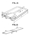
- FIG. 5 shows a discrete element of the power divider, the central strip 3 of which ends, for example, by two branches 20a and 20b each intended to supply power to a radiating source (not shown).
- non-limiting examples will be the production of a radiating element, such as for example a half-wave dipole, and the production of a ring.
- the conductive strips 22 and 23 of the two lines intended to be connected com carry two complementary recesses 25 and 26, obtained for example by chemical cutting, and formed on their respective ends.
- the two ribbons 22 and 23 are fitted one inside the other, then are fixed to each other, for example by welding. It will be noted that this connection system by complementary steps allows the ribbons, once connected, to maintain good temperature resistance.
- the applicant has produced a three-plate air line transmitting a power greater than 40 KW peak, and generating losses of the order of 0.2 dB / m in "S" band.
Landscapes
- Waveguide Aerials (AREA)
- Communication Cables (AREA)
- Waveguides (AREA)
- Building Environments (AREA)
- Separation By Low-Temperature Treatments (AREA)
- Insulated Conductors (AREA)
- Duct Arrangements (AREA)
- Details Of Connecting Devices For Male And Female Coupling (AREA)
Priority Applications (1)
| Application Number | Priority Date | Filing Date | Title |
|---|---|---|---|
| AT81401892T ATE15300T1 (de) | 1980-12-18 | 1981-11-27 | Luftgefuellte triplateleitung fuer den hochfrequenzbereich und ihre anwendungen. |
Applications Claiming Priority (2)
| Application Number | Priority Date | Filing Date | Title |
|---|---|---|---|
| FR8026912 | 1980-12-18 | ||
| FR8026912A FR2496996A1 (fr) | 1980-12-18 | 1980-12-18 | Ligne de transmission hyperfrequence, du type triplaque a air et ses utilisations |
Publications (2)
| Publication Number | Publication Date |
|---|---|
| EP0055642A1 true EP0055642A1 (de) | 1982-07-07 |
| EP0055642B1 EP0055642B1 (de) | 1985-08-28 |
Family
ID=9249248
Family Applications (1)
| Application Number | Title | Priority Date | Filing Date |
|---|---|---|---|
| EP81401892A Expired EP0055642B1 (de) | 1980-12-18 | 1981-11-27 | Luftgefüllte Triplateleitung für den Hochfrequenzbereich und ihre Anwendungen |
Country Status (8)
| Country | Link |
|---|---|
| US (1) | US4437074A (de) |
| EP (1) | EP0055642B1 (de) |
| JP (1) | JPS57129504A (de) |
| AT (1) | ATE15300T1 (de) |
| CA (1) | CA1189157A (de) |
| DE (1) | DE3172075D1 (de) |
| DK (1) | DK552881A (de) |
| FR (1) | FR2496996A1 (de) |
Cited By (3)
| Publication number | Priority date | Publication date | Assignee | Title |
|---|---|---|---|---|
| FR2629275A1 (fr) * | 1988-03-22 | 1989-09-29 | Thomson Csf | Piece de maintien mecanique pour circuits hyperfrequences |
| EP0478962A3 (en) * | 1990-10-05 | 1993-04-21 | Rohde & Schwarz Gmbh & Co. Kg | Microwave-stripline assembly |
| EP0801433A1 (de) * | 1996-04-12 | 1997-10-15 | Harris Corporation | Steifenleiter mit Luft als Dielektrikum |
Families Citing this family (33)
| Publication number | Priority date | Publication date | Assignee | Title |
|---|---|---|---|---|
| FR2640083B1 (fr) * | 1988-12-06 | 1991-05-03 | Thomson Csf | Support pour ligne de transmission hyperfrequence, notamment du type triplaque |
| US5159154A (en) * | 1990-08-21 | 1992-10-27 | Thinking Machines Corporation | Multiple conductor dielectric cable assembly and method of manufacture |
| DE4032260C1 (en) * | 1990-10-11 | 1992-04-23 | Ant Nachrichtentechnik Gmbh, 7150 Backnang, De | Microwave strip conductor - has conductive track formed on surface of substrate, e.g. gallium arsenide |
| FI113577B (fi) * | 1999-06-29 | 2004-05-14 | Filtronic Lk Oy | Alipäästösuodatin |
| US20020125967A1 (en) * | 2000-11-03 | 2002-09-12 | Garrett Richard H. | Air dielectric backplane interconnection system |
| CA2503793A1 (en) | 2002-10-22 | 2004-05-06 | Jason A. Sullivan | Systems and methods for providing a dynamically modular processing unit |
| CA2504222C (en) | 2002-10-22 | 2012-05-22 | Jason A. Sullivan | Robust customizable computer processing system |
| EP1557075A4 (de) | 2002-10-22 | 2010-01-13 | Sullivan Jason | Nicht-peripheres verarbeitungssteuermodul mit verbesserten wärmeableiteigenschaften |
| ATE475999T1 (de) | 2003-03-04 | 2010-08-15 | Rohm & Haas Elect Mat | Koaxiale wellenleitermikrostrukturen und verfahern zu ihrer bildung |
| EP2064773A1 (de) * | 2006-09-22 | 2009-06-03 | Powerwave Technologies Sweden AB | Verfahren zur herstellung einer übertragungsleitung mit transvers-elektrisch-magnetisch-modus (tem) und eine solche übertragungsleitung |
| JP2008188755A (ja) | 2006-12-30 | 2008-08-21 | Rohm & Haas Electronic Materials Llc | 三次元微細構造体およびその形成方法 |
| EP1973190A1 (de) | 2007-03-20 | 2008-09-24 | Rohm and Haas Electronic Materials LLC | Integrierte elektronische Komponenten und Herstellungsverfahren dafür |
| EP1973189B1 (de) | 2007-03-20 | 2012-12-05 | Nuvotronics, LLC | Mikrostrukturen einer koaxialen Übertragungsleitung und Herstellungsverfahren dafür |
| US8228139B2 (en) * | 2008-03-19 | 2012-07-24 | Powerwave Technologies Sweden Ab | Transmission line comprised of a center conductor on a printed circuit board disposed within a groove |
| US20210130285A1 (en) | 2008-03-19 | 2021-05-06 | Aurimmed Pharma, Inc. | Novel compounds advantageous in the treatment of central nervous system diseases and disorders |
| US8659371B2 (en) * | 2009-03-03 | 2014-02-25 | Bae Systems Information And Electronic Systems Integration Inc. | Three-dimensional matrix structure for defining a coaxial transmission line channel |
| US20110123783A1 (en) | 2009-11-23 | 2011-05-26 | David Sherrer | Multilayer build processses and devices thereof |
| KR101917052B1 (ko) | 2010-01-22 | 2019-01-30 | 누보트로닉스, 인크. | 열관리 |
| US8917150B2 (en) * | 2010-01-22 | 2014-12-23 | Nuvotronics, Llc | Waveguide balun having waveguide structures disposed over a ground plane and having probes located in channels |
| WO2012109393A1 (en) | 2011-02-08 | 2012-08-16 | Henry Cooper | High gain frequency step horn antenna |
| WO2012109498A1 (en) | 2011-02-09 | 2012-08-16 | Henry Cooper | Corrugated horn antenna with enhanced frequency range |
| US8866300B1 (en) | 2011-06-05 | 2014-10-21 | Nuvotronics, Llc | Devices and methods for solder flow control in three-dimensional microstructures |
| US8814601B1 (en) | 2011-06-06 | 2014-08-26 | Nuvotronics, Llc | Batch fabricated microconnectors |
| JP6335782B2 (ja) | 2011-07-13 | 2018-05-30 | ヌボトロニクス、インク. | 電子的および機械的な構造を製作する方法 |
| US9325044B2 (en) | 2013-01-26 | 2016-04-26 | Nuvotronics, Inc. | Multi-layer digital elliptic filter and method |
| US9306254B1 (en) | 2013-03-15 | 2016-04-05 | Nuvotronics, Inc. | Substrate-free mechanical interconnection of electronic sub-systems using a spring configuration |
| US9306255B1 (en) | 2013-03-15 | 2016-04-05 | Nuvotronics, Inc. | Microstructure including microstructural waveguide elements and/or IC chips that are mechanically interconnected to each other |
| US9450309B2 (en) | 2013-05-30 | 2016-09-20 | Xi3 | Lobe antenna |
| WO2015109208A2 (en) | 2014-01-17 | 2015-07-23 | Nuvotronics, Llc | Wafer scale test interface unit: low loss and high isolation devices and methods for high speed and high density mixed signal interconnects and contactors |
| WO2016007958A2 (en) * | 2014-07-11 | 2016-01-14 | Xi3, Inc. | Systems and methods for providing a high power pc board air dielectric splitter |
| US10847469B2 (en) | 2016-04-26 | 2020-11-24 | Cubic Corporation | CTE compensation for wafer-level and chip-scale packages and assemblies |
| US10511073B2 (en) | 2014-12-03 | 2019-12-17 | Cubic Corporation | Systems and methods for manufacturing stacked circuits and transmission lines |
| US10319654B1 (en) | 2017-12-01 | 2019-06-11 | Cubic Corporation | Integrated chip scale packages |
Citations (5)
| Publication number | Priority date | Publication date | Assignee | Title |
|---|---|---|---|---|
| US2937347A (en) * | 1958-01-02 | 1960-05-17 | Thompson Ramo Wooldridge Inc | Filter |
| GB864016A (en) * | 1958-09-17 | 1961-03-29 | Radio Heaters Ltd | Improvements in or relating to radio frequency feeders |
| US2984802A (en) * | 1954-11-17 | 1961-05-16 | Cutler Hammer Inc | Microwave circuits |
| FR1573432A (de) * | 1967-07-06 | 1969-07-04 | ||
| FR2102158A1 (de) * | 1970-08-10 | 1972-04-07 | Int Standard Electric Corp |
Family Cites Families (3)
| Publication number | Priority date | Publication date | Assignee | Title |
|---|---|---|---|---|
| US2877427A (en) | 1955-10-11 | 1959-03-10 | Sanders Associates Inc | Parallel transmission line circuit |
| US3303439A (en) | 1965-06-14 | 1967-02-07 | Western Electric Co | Strip transmission line interboard connection |
| US4365222A (en) | 1981-04-06 | 1982-12-21 | Bell Telephone Laboratories, Incorporated | Stripline support assembly |
-
1980
- 1980-12-18 FR FR8026912A patent/FR2496996A1/fr active Granted
-
1981
- 1981-11-27 AT AT81401892T patent/ATE15300T1/de not_active IP Right Cessation
- 1981-11-27 EP EP81401892A patent/EP0055642B1/de not_active Expired
- 1981-11-27 DE DE8181401892T patent/DE3172075D1/de not_active Expired
- 1981-12-14 CA CA000392167A patent/CA1189157A/en not_active Expired
- 1981-12-14 DK DK552881A patent/DK552881A/da not_active Application Discontinuation
- 1981-12-14 US US06/330,319 patent/US4437074A/en not_active Expired - Fee Related
- 1981-12-16 JP JP56204481A patent/JPS57129504A/ja active Pending
Patent Citations (5)
| Publication number | Priority date | Publication date | Assignee | Title |
|---|---|---|---|---|
| US2984802A (en) * | 1954-11-17 | 1961-05-16 | Cutler Hammer Inc | Microwave circuits |
| US2937347A (en) * | 1958-01-02 | 1960-05-17 | Thompson Ramo Wooldridge Inc | Filter |
| GB864016A (en) * | 1958-09-17 | 1961-03-29 | Radio Heaters Ltd | Improvements in or relating to radio frequency feeders |
| FR1573432A (de) * | 1967-07-06 | 1969-07-04 | ||
| FR2102158A1 (de) * | 1970-08-10 | 1972-04-07 | Int Standard Electric Corp |
Non-Patent Citations (3)
| Title |
|---|
| A.F. HARVEY: "MICROWAVE ENGINEERING 1963, Academic Press LONDRES (GB) page 408 * |
| H. MEINKE et al.: "TASCHENBUCH DER HOCHFREQUENZTECHNIK", édition 2, 1962, Springer-Verlag BERLIN (DE) pages 257, 357 * |
| Th. MORENO: "MICROWAVE TRANSMISSION DESIGN DATA, édition 1, 1948 McGraw-Hill Book Company NEW YORK (US) pages 87,88,94 * |
Cited By (3)
| Publication number | Priority date | Publication date | Assignee | Title |
|---|---|---|---|---|
| FR2629275A1 (fr) * | 1988-03-22 | 1989-09-29 | Thomson Csf | Piece de maintien mecanique pour circuits hyperfrequences |
| EP0478962A3 (en) * | 1990-10-05 | 1993-04-21 | Rohde & Schwarz Gmbh & Co. Kg | Microwave-stripline assembly |
| EP0801433A1 (de) * | 1996-04-12 | 1997-10-15 | Harris Corporation | Steifenleiter mit Luft als Dielektrikum |
Also Published As
| Publication number | Publication date |
|---|---|
| DK552881A (da) | 1982-06-19 |
| ATE15300T1 (de) | 1985-09-15 |
| FR2496996A1 (fr) | 1982-06-25 |
| CA1189157A (en) | 1985-06-18 |
| FR2496996B1 (de) | 1983-01-21 |
| US4437074A (en) | 1984-03-13 |
| EP0055642B1 (de) | 1985-08-28 |
| DE3172075D1 (en) | 1985-10-03 |
| JPS57129504A (en) | 1982-08-11 |
Similar Documents
| Publication | Publication Date | Title |
|---|---|---|
| EP0055642A1 (de) | Luftgefüllte Triplateleitung für den Hochfrequenzbereich und ihre Anwendungen | |
| EP2510574B1 (de) | Mikrowellenübergangsvorrichtung zwischen einer mikrostripleitung und einem rechteckigen wellenleiter | |
| EP0330525B1 (de) | Vorgefertigte elektrische Kanalisation, anwendbar auf mehrere Nennströme vom Typ bestehend aus einem flachen kannelierten Isolationsträger für Leiterschienen | |
| EP0373052A1 (de) | Trägerelement für eine Übertragungsleitung, insbesondere vom Streifenleitungstyp | |
| EP0134611B1 (de) | Sende- oder Empfangsstrahlergruppe einer Mikrowellenflachantenne und Sende- oder Empfangseinrichtung von Mikrowellensignalen mit einer solchen Flachantenne | |
| FR2989842A1 (fr) | Ligne de propagation radiofrequence a ondes lentes | |
| EP1042845B1 (de) | Antenne | |
| FR2558991A1 (fr) | Antenne a reflecteur pour le fonctionnement dans plusieurs gammes de frequence | |
| FR2747513A1 (fr) | Antenne notamment pour systeme antivol d'un vehicule automobile | |
| EP2401786A1 (de) | Mechanische und elektrische verbindungsvorrichtung für ein koaxialkabel zur übermittlung eines hochfrequenzsignals | |
| EP0033697B1 (de) | Vielfach-Kondensator mit hoher Wärmeabfuhr | |
| EP0378635B1 (de) | Oszillator hoher frequenzstabilität für den betrieb bei normalem luftdruck und im vakuum | |
| EP3888154A1 (de) | Batteriegehäuse und modulares batteriesystem | |
| FR2764739A1 (fr) | Antenne reseau a fentes rayonnantes | |
| EP0068946B1 (de) | Verfahren zum Herstellen eines Einheitsbauelementes mit einer Oszillatordiode und einer Varaktordiode, und frequenzabstimmbare Sender mit solchem Einheitsbauelement | |
| EP0117804B1 (de) | Herstellungsverfahren eines Mikrowellenhohlraumresonators und nach diesem Verfahren hergestellter Hohlraumresonator | |
| EP3721501A1 (de) | Mikrowellen-bauelement und zugehöriges herstellungsverfahren | |
| EP0136941B1 (de) | Millimeterwellenschalter | |
| FR2461369A1 (fr) | Element coaxial pour hyperfrequences, son procede de realisation, et composant hyperfrequence comprenant un tel element | |
| EP1376758B1 (de) | Kompakte Streifenleiterantenne mit einer Anpassungsanordnung | |
| US4459562A (en) | Dielectric based submillimeter backward wave oscillator circuit | |
| JP2001044745A (ja) | 導波管アンテナ | |
| EP0134163B1 (de) | Koaxialdurchführung einer Metallwandung | |
| FR2660803A1 (fr) | Dispositif et piece de raccordement pour guides d'ondes hyperfrequence. | |
| EP0637047B1 (de) | Kathode mit schnell schaltendem Heizelement und Gitter-Elektronenröhre ausgerüstet mit einer solchen Kathode |
Legal Events
| Date | Code | Title | Description |
|---|---|---|---|
| PUAI | Public reference made under article 153(3) epc to a published international application that has entered the european phase |
Free format text: ORIGINAL CODE: 0009012 |
|
| AK | Designated contracting states |
Designated state(s): AT BE CH DE GB IT LI NL SE |
|
| 17P | Request for examination filed |
Effective date: 19821215 |
|
| ITF | It: translation for a ep patent filed | ||
| GRAA | (expected) grant |
Free format text: ORIGINAL CODE: 0009210 |
|
| AK | Designated contracting states |
Designated state(s): AT BE CH DE GB IT LI NL SE |
|
| REF | Corresponds to: |
Ref document number: 15300 Country of ref document: AT Date of ref document: 19850915 Kind code of ref document: T |
|
| REF | Corresponds to: |
Ref document number: 3172075 Country of ref document: DE Date of ref document: 19851003 |
|
| PLBE | No opposition filed within time limit |
Free format text: ORIGINAL CODE: 0009261 |
|
| STAA | Information on the status of an ep patent application or granted ep patent |
Free format text: STATUS: NO OPPOSITION FILED WITHIN TIME LIMIT |
|
| 26N | No opposition filed | ||
| PGFP | Annual fee paid to national office [announced via postgrant information from national office to epo] |
Ref country code: AT Payment date: 19861128 Year of fee payment: 6 |
|
| PGFP | Annual fee paid to national office [announced via postgrant information from national office to epo] |
Ref country code: DE Payment date: 19891023 Year of fee payment: 9 |
|
| PGFP | Annual fee paid to national office [announced via postgrant information from national office to epo] |
Ref country code: SE Payment date: 19891024 Year of fee payment: 9 |
|
| PGFP | Annual fee paid to national office [announced via postgrant information from national office to epo] |
Ref country code: GB Payment date: 19891031 Year of fee payment: 9 |
|
| PG25 | Lapsed in a contracting state [announced via postgrant information from national office to epo] |
Ref country code: AT Effective date: 19891127 |
|
| ITTA | It: last paid annual fee | ||
| PG25 | Lapsed in a contracting state [announced via postgrant information from national office to epo] |
Ref country code: LI Effective date: 19891130 Ref country code: CH Effective date: 19891130 Ref country code: BE Effective date: 19891130 |
|
| PGFP | Annual fee paid to national office [announced via postgrant information from national office to epo] |
Ref country code: NL Payment date: 19891130 Year of fee payment: 9 |
|
| BERE | Be: lapsed |
Owner name: THOMSON-CSF Effective date: 19891130 |
|
| REG | Reference to a national code |
Ref country code: CH Ref legal event code: PL |
|
| PG25 | Lapsed in a contracting state [announced via postgrant information from national office to epo] |
Ref country code: GB Effective date: 19901127 |
|
| PG25 | Lapsed in a contracting state [announced via postgrant information from national office to epo] |
Ref country code: SE Effective date: 19901128 |
|
| PG25 | Lapsed in a contracting state [announced via postgrant information from national office to epo] |
Ref country code: NL Effective date: 19910601 |
|
| NLV4 | Nl: lapsed or anulled due to non-payment of the annual fee | ||
| GBPC | Gb: european patent ceased through non-payment of renewal fee | ||
| PG25 | Lapsed in a contracting state [announced via postgrant information from national office to epo] |
Ref country code: DE Effective date: 19910801 |
|
| EUG | Se: european patent has lapsed |
Ref document number: 81401892.5 Effective date: 19910705 |