EP0055654A1 - Pompe distributrice à piston libre commandé par une électrovanne unique - Google Patents
Pompe distributrice à piston libre commandé par une électrovanne unique Download PDFInfo
- Publication number
- EP0055654A1 EP0055654A1 EP81402001A EP81402001A EP0055654A1 EP 0055654 A1 EP0055654 A1 EP 0055654A1 EP 81402001 A EP81402001 A EP 81402001A EP 81402001 A EP81402001 A EP 81402001A EP 0055654 A1 EP0055654 A1 EP 0055654A1
- Authority
- EP
- European Patent Office
- Prior art keywords
- fuel
- chamber
- timing
- metering chamber
- metering
- Prior art date
- Legal status (The legal status is an assumption and is not a legal conclusion. Google has not performed a legal analysis and makes no representation as to the accuracy of the status listed.)
- Withdrawn
Links
Images

Classifications
-
- F—MECHANICAL ENGINEERING; LIGHTING; HEATING; WEAPONS; BLASTING
- F02—COMBUSTION ENGINES; HOT-GAS OR COMBUSTION-PRODUCT ENGINE PLANTS
- F02M—SUPPLYING COMBUSTION ENGINES IN GENERAL WITH COMBUSTIBLE MIXTURES OR CONSTITUENTS THEREOF
- F02M59/00—Pumps specially adapted for fuel-injection and not provided for in groups F02M39/00 -F02M57/00, e.g. rotary cylinder-block type of pumps
- F02M59/20—Varying fuel delivery in quantity or timing
- F02M59/32—Varying fuel delivery in quantity or timing fuel delivery being controlled by means of fuel-displaced auxiliary pistons, which effect injection
-
- F—MECHANICAL ENGINEERING; LIGHTING; HEATING; WEAPONS; BLASTING
- F02—COMBUSTION ENGINES; HOT-GAS OR COMBUSTION-PRODUCT ENGINE PLANTS
- F02M—SUPPLYING COMBUSTION ENGINES IN GENERAL WITH COMBUSTIBLE MIXTURES OR CONSTITUENTS THEREOF
- F02M41/00—Fuel-injection apparatus with two or more injectors fed from a common pressure-source sequentially by means of a distributor
- F02M41/02—Fuel-injection apparatus with two or more injectors fed from a common pressure-source sequentially by means of a distributor the distributor being spaced from pumping elements
- F02M41/06—Fuel-injection apparatus with two or more injectors fed from a common pressure-source sequentially by means of a distributor the distributor being spaced from pumping elements the distributor rotating
-
- F—MECHANICAL ENGINEERING; LIGHTING; HEATING; WEAPONS; BLASTING
- F02—COMBUSTION ENGINES; HOT-GAS OR COMBUSTION-PRODUCT ENGINE PLANTS
- F02M—SUPPLYING COMBUSTION ENGINES IN GENERAL WITH COMBUSTIBLE MIXTURES OR CONSTITUENTS THEREOF
- F02M59/00—Pumps specially adapted for fuel-injection and not provided for in groups F02M39/00 -F02M57/00, e.g. rotary cylinder-block type of pumps
- F02M59/20—Varying fuel delivery in quantity or timing
- F02M59/36—Varying fuel delivery in quantity or timing by variably-timed valves controlling fuel passages to pumping elements or overflow passages
- F02M59/366—Valves being actuated electrically
Definitions
- This invention is generally related to distributor type fuel injection pumps for controlling the quantity and timing of injection of fuel into the cylinder of an engine, and in particular is related to a distributor type fuel injection pump in which the metering and timing of injection of fuel is controlled by a single electromagnetic control valve.
- the invention is a distributor type fuel injection pump in which the injection timing and fuel metering is controlled by a single electromagnetic control device, wherein the fuel for an injection into a particular cylinder is premetered prior to that injection.
- the rotation of the engine causes the rotation of a cam mounted on a shaft which is rotating at a speed which is half the speed of a four-stroke-cycle engine rotation.
- the cam operates to drive a piston in a cavity, the cavity also forming a metering chamber and a timing chamber, the two chambers being separated by a free piston.
- the point of injection is selected by an electronic control unit and a pulse is generated to either energize or de-energize a control valve. This creates a hydraulic link between the driving piston or primary piston and the free piston, thereby driving the floating piston into the chamber.
- the fuel may flow into the metering chamber in accordance with a pressure-time metering concept with a restricted oriface or a volumetric metering concept determined by the position of the piston.
- the control valve is de-energized and the subsequent movement of the driving piston out of the chamber allows fuel to enter into the timing chamber.
- the system is prepared for the next injection of fuel into a different cylinder of the engine.
- a single control solenoid, and a single pulse from an electronic control unit is utilized to control the initiation of injection of fuel into a particular cylinder and also to control the amount of fuel that is to be injected into the next cylinder of the engine.
- the control valve may be very fast acting and thus precise control of timing and metering may be accomplished with the system of the present invention.
- the pump 10 includes a gear type driving mechanism 12, a timing and premetering assembly 14, the fuel output from the timing and premetering assembly 14 being fed to a distribution head 16 which controls the particular cylinder to which each pulse of fuel is fed in the internal combustion engine.
- the control of the timing and premetering assembly 14 is accomplished by a electromagnetic solenoid control unit 18.
- the driving mechanism 12 is basically a gear assembly including a main gear 20 which is driven from the engine with which the distribution pump is associated.
- the gear 20 is driven at half the speed of the engine thereby rotating one revolution per two revolutions of the engine.
- the gear 20 is mounted on a shaft (not shown) which drives a second gear 22 which can be of reduced diameter relative to the gear 20.
- Gear 22 in turn drives a gear 24 which is mounted on a shaft 26, the shaft.26 rotating at the same speed as that of the gear 20, the particular application illustrated being utilized in a four cycle engine.
- the rotation of the shaft 26 will drive a cam 28.
- the cam is utilized to drive the timing and premetering assembly 14 in a manner to be described.
- the configuration and operation of the timing and premetering section 14 is very similar to that described in the above-referenced application 6,948 and U.S. Patent No. 4,235,374.
- U.S. Patent No. 4,235,374.
- Fuel is introduced to the distribution pump by means of a conduit 36, the conduit 36 supplying fuel to the internal case of the distribution pump.
- the supply of fuel is fed from conduit 36 through a passageway 38 formed in the body of the timing and premetering section 14.
- this fuel is fed to a timing chamber 40 by means of a passageway 42 through a check valve 44.
- Fuel is also fed to the control valve 18 by means of a passageway 48, the output of the control valve being fed to a timing chamber 50 by means of a passageway 52.
- the metering chamber 40 and the timing chamber 50 are separated by means of a floating piston 56.
- the rotational motion of the shaft 26 and cam 28 are translated into reciprocating motion by means of a driving piston 58.
- the piston 58 is urged toward the cam element 28 by means of a spring 62.
- the fuel pulse output from the metering chamber is fed to the distribution head 16 by means of a passageway 64.
- the distribution head is driven by the same shaft which is driving the gear 22.
- the output of the distribution head 16 is synchronized with the opration of the cam 28.
- the distribution head 16 includes a plurality of output connectors 70, one connector being connected to each cylinder of the internal combution engine being controlled. An embodiment of a distribution head will be described in conjunction with the description of Figure 2.
- the shaft 26 In operation, and assuming that a preselected amount of fuel has been metered into metering chamber 40, and the piston 58 is at its downmost position, the shaft 26 is rotated and the cam surface forces driving piston upwardly against the action of the spring 62. During this part of the operation, the control valve 18 is in a state such that fuel can flow from the timing chamber 50 out through passageway 52 and back to the source of fuel supply. At the point in the rotation of the engine at which injection is to occur, the control solenoid 18 is energized to preclude fuel flow out of the timing chamber and thus pressurize the fuel in the timing chamber.
- the continued motion of the driving piston 58 pressurizes the fuel in the metering chamber 40 and causes pressurized fuel to be injected from an injection connected to a line (not shown) connected to one of the output connectors 70, depending on the position of the distributor head.
- This drives piston 56 upwardly until such time as a passageway 72 is put into fluid communication with the passageway shown in the free piston 56.
- This dumps fuel from the metering chamber 40 and reduces the pressure therein.
- the passageway- which contains the check valve 74 is put into fluid communication with the-timing chamber to permit fuel to be dumped from the timing chamber as the piston 58 is driven further into the timing chamber.
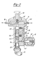
- FIG. 2 there is illustrated some schematic details of the control solenoid 18 and the distribution head 16, the details being shown in schematic fashion to illustrate the principle of the present invention.
- a cam 80 shown schematically for a single injection cycle, drives piston 58 upwardly into the timing chamber 50.
- the control solenoid 18 is illustrated as having a coil 82 which electromagnetically controls the position of an armature 84, the end of the armature having formed thereon a control valve shown in the form of a ball 86. In the position shown, the coil 82 is de-energized and piston 58 is driven upwardly into the timing chamber 50.
- solenoid 82 is energized to pull ball 86 to the right and shut off a passageway 90.
- fuel Prior to the ball shutting off the passageway 90, fuel is permitted to flow from the timing chamber, through passageway 42 and back to the supply by means of a passageway 38.
- ball 86 When ball 86 is seated, the fuel in the timing chamber 50 is pressurized which in turn pressurizes the fuel in metering chamber 40.
- the free piston -56 With further upward movement of piston 58, the free piston -56 is driven upwardly to cause fuel to be pressurized in the distribution head 16.
- This pressurized fuel causes a valve, including a ball 92, which ball 92 is unseated to force pressurized fuel out to the engine cylinder by means of a passageway 96.
- the distribution head includes a shaft 98 which is rotated in synchronism with the cam 80, thus distributing each pulse of fuel to the respective cylinders.
- the cylinder associated with conduit 96 is provided a pulse of fuel and the cylinder associated with a conduit 100 is provided a pulse of fuel one engine revolution later than that provided in the cylinder connected to 96.
Landscapes
- Engineering & Computer Science (AREA)
- Chemical & Material Sciences (AREA)
- Combustion & Propulsion (AREA)
- Mechanical Engineering (AREA)
- General Engineering & Computer Science (AREA)
- Fuel-Injection Apparatus (AREA)
Applications Claiming Priority (2)
| Application Number | Priority Date | Filing Date | Title |
|---|---|---|---|
| US21731180A | 1980-12-17 | 1980-12-17 | |
| US217311 | 1980-12-17 |
Publications (1)
| Publication Number | Publication Date |
|---|---|
| EP0055654A1 true EP0055654A1 (fr) | 1982-07-07 |
Family
ID=22810524
Family Applications (1)
| Application Number | Title | Priority Date | Filing Date |
|---|---|---|---|
| EP81402001A Withdrawn EP0055654A1 (fr) | 1980-12-17 | 1981-12-15 | Pompe distributrice à piston libre commandé par une électrovanne unique |
Country Status (5)
| Country | Link |
|---|---|
| EP (1) | EP0055654A1 (fr) |
| JP (1) | JPS57124066A (fr) |
| BR (1) | BR8108163A (fr) |
| CA (1) | CA1170903A (fr) |
| ES (1) | ES508050A0 (fr) |
Cited By (5)
| Publication number | Priority date | Publication date | Assignee | Title |
|---|---|---|---|---|
| US4583510A (en) * | 1985-01-07 | 1986-04-22 | Ford Motor Company | Electromagnetic distributor-type multiplunger fuel injection pump |
| EP0320462A1 (fr) * | 1987-12-09 | 1989-06-14 | WEBER S.r.l. | Pompe à injection de combustible pour systèmes d'injection de moteurs diesel, avec cylindre de volume variable |
| GB2284024B (en) * | 1993-05-06 | 1997-04-02 | Cummins Engine Co Inc | Variable displacement high pressure pump for common rail fuel injection systems |
| WO1999054271A1 (fr) | 1998-04-21 | 1999-10-28 | Daicel Chemical Industries, Ltd. | Derives d'adamantanemethanol et procede de preparation de ces derniers |
| CN106968854A (zh) * | 2016-12-13 | 2017-07-21 | 俞扬池 | 一种柴油发动机燃油分配器 |
Families Citing this family (1)
| Publication number | Priority date | Publication date | Assignee | Title |
|---|---|---|---|---|
| JPH02168583A (ja) * | 1988-12-21 | 1990-06-28 | Kyushu Hitachi Maxell Ltd | コード接続器 |
Citations (5)
| Publication number | Priority date | Publication date | Assignee | Title |
|---|---|---|---|---|
| DE1919969A1 (de) * | 1969-04-19 | 1970-11-12 | Bosch Gmbh Robert | Kraftstoffeinspritzpumpe fuer Brennkraftmaschinen |
| GB1306442A (en) * | 1969-07-02 | 1973-02-14 | Eaton Corp | Couplings |
| US3951117A (en) * | 1974-05-30 | 1976-04-20 | Cummins Engine Company, Inc. | Fuel supply system for an internal combustion engine |
| EP0014142A1 (fr) * | 1979-01-25 | 1980-08-06 | AlliedSignal Inc. | Injecteur de combustible avec contrôle éléctronique |
| US4235374A (en) * | 1979-01-25 | 1980-11-25 | The Bendix Corporation | Electronically controlled diesel unit injector |
-
1981
- 1981-11-26 CA CA000391022A patent/CA1170903A/fr not_active Expired
- 1981-12-15 EP EP81402001A patent/EP0055654A1/fr not_active Withdrawn
- 1981-12-16 BR BR8108163A patent/BR8108163A/pt unknown
- 1981-12-16 ES ES508050A patent/ES508050A0/es active Granted
- 1981-12-17 JP JP20260581A patent/JPS57124066A/ja active Pending
Patent Citations (5)
| Publication number | Priority date | Publication date | Assignee | Title |
|---|---|---|---|---|
| DE1919969A1 (de) * | 1969-04-19 | 1970-11-12 | Bosch Gmbh Robert | Kraftstoffeinspritzpumpe fuer Brennkraftmaschinen |
| GB1306442A (en) * | 1969-07-02 | 1973-02-14 | Eaton Corp | Couplings |
| US3951117A (en) * | 1974-05-30 | 1976-04-20 | Cummins Engine Company, Inc. | Fuel supply system for an internal combustion engine |
| EP0014142A1 (fr) * | 1979-01-25 | 1980-08-06 | AlliedSignal Inc. | Injecteur de combustible avec contrôle éléctronique |
| US4235374A (en) * | 1979-01-25 | 1980-11-25 | The Bendix Corporation | Electronically controlled diesel unit injector |
Cited By (6)
| Publication number | Priority date | Publication date | Assignee | Title |
|---|---|---|---|---|
| US4583510A (en) * | 1985-01-07 | 1986-04-22 | Ford Motor Company | Electromagnetic distributor-type multiplunger fuel injection pump |
| EP0320462A1 (fr) * | 1987-12-09 | 1989-06-14 | WEBER S.r.l. | Pompe à injection de combustible pour systèmes d'injection de moteurs diesel, avec cylindre de volume variable |
| US4928656A (en) * | 1987-12-09 | 1990-05-29 | Weber S.R.L. | Fuel-injection pump with variable cylinder capacity for diesel engine injection systems |
| GB2284024B (en) * | 1993-05-06 | 1997-04-02 | Cummins Engine Co Inc | Variable displacement high pressure pump for common rail fuel injection systems |
| WO1999054271A1 (fr) | 1998-04-21 | 1999-10-28 | Daicel Chemical Industries, Ltd. | Derives d'adamantanemethanol et procede de preparation de ces derniers |
| CN106968854A (zh) * | 2016-12-13 | 2017-07-21 | 俞扬池 | 一种柴油发动机燃油分配器 |
Also Published As
| Publication number | Publication date |
|---|---|
| ES8300941A1 (es) | 1982-11-01 |
| JPS57124066A (en) | 1982-08-02 |
| BR8108163A (pt) | 1982-09-28 |
| CA1170903A (fr) | 1984-07-17 |
| ES508050A0 (es) | 1982-11-01 |
Similar Documents
| Publication | Publication Date | Title |
|---|---|---|
| US4777921A (en) | Fuel injection system | |
| US4628881A (en) | Pressure-controlled fuel injection for internal combustion engines | |
| US4449507A (en) | Dual pressure metering for distributor pumps | |
| US4782803A (en) | Fuel injection control method for fuel injection pump | |
| EP1429020B1 (fr) | Pompe à écoulement variable | |
| EP0548000A2 (fr) | Pompe à injection de combustible distributrice | |
| JPH07180635A (ja) | 燃料供給装置 | |
| EP0055171B1 (fr) | Pompe distributrice ayant un piston libre commandé par une valve unique | |
| EP0957261B1 (fr) | Système de carburant et pompe utilisable dans ce système | |
| US5762033A (en) | Injection device for combined injection of fuel and supplementary fluid or liquid | |
| CA1124599A (fr) | Pompe d'injection de combustible commandee par electrovanne | |
| EP0429205B1 (fr) | Pompe d'injection à distribution de combustible à commande électronique | |
| US4485787A (en) | Fuel injection system | |
| US4426977A (en) | Dual solenoid distributor pump system | |
| US4418671A (en) | Dual solenoid distributor pump | |
| EP0055654A1 (fr) | Pompe distributrice à piston libre commandé par une électrovanne unique | |
| EP0107894A2 (fr) | Méthode et appareil pour la commande de précision de l'injection de carburant dans un moteur diesel | |
| CN1010336B (zh) | 柴油机的燃油喷射装置 | |
| US3859972A (en) | Fuel injection system for an internal combustion engine | |
| GB2275307A (en) | I.c.engine high pressure distributor fuel injection system | |
| EP0055653B1 (fr) | Pompe d'injection distributrice | |
| GB2278648A (en) | A fuel-injection device for an internal combustion engine | |
| US6267086B1 (en) | Fuel system | |
| US4537352A (en) | Fuel injection apparatus | |
| JPH0362907B2 (fr) |
Legal Events
| Date | Code | Title | Description |
|---|---|---|---|
| PUAI | Public reference made under article 153(3) epc to a published international application that has entered the european phase |
Free format text: ORIGINAL CODE: 0009012 |
|
| 17P | Request for examination filed |
Effective date: 19811218 |
|
| AK | Designated contracting states |
Designated state(s): AT DE FR GB IT |
|
| STAA | Information on the status of an ep patent application or granted ep patent |
Free format text: STATUS: THE APPLICATION IS DEEMED TO BE WITHDRAWN |
|
| 18D | Application deemed to be withdrawn |
Effective date: 19840809 |
|
| RIN1 | Information on inventor provided before grant (corrected) |
Inventor name: PHIPPS, JACK RALPH |