EP0055655A2 - Verfahren und Vorrichtung, um mittels einer einstellbaren Strahlungsquelle einen beleuchteten Körper optisch darzustellen - Google Patents
Verfahren und Vorrichtung, um mittels einer einstellbaren Strahlungsquelle einen beleuchteten Körper optisch darzustellen Download PDFInfo
- Publication number
- EP0055655A2 EP0055655A2 EP81402005A EP81402005A EP0055655A2 EP 0055655 A2 EP0055655 A2 EP 0055655A2 EP 81402005 A EP81402005 A EP 81402005A EP 81402005 A EP81402005 A EP 81402005A EP 0055655 A2 EP0055655 A2 EP 0055655A2
- Authority
- EP
- European Patent Office
- Prior art keywords
- signal
- signals
- video
- radiation
- function
- Prior art date
- Legal status (The legal status is an assumption and is not a legal conclusion. Google has not performed a legal analysis and makes no representation as to the accuracy of the status listed.)
- Granted
Links
Images

Classifications
-
- H—ELECTRICITY
- H04—ELECTRIC COMMUNICATION TECHNIQUE
- H04N—PICTORIAL COMMUNICATION, e.g. TELEVISION
- H04N5/00—Details of television systems
- H04N5/30—Transforming light or analogous information into electric information
- H04N5/32—Transforming X-rays
- H04N5/3205—Transforming X-rays using subtraction imaging techniques
Definitions
- the present invention relates to a device and method for viewing a body lit by an adjustable radiation source.
- the present invention relates to improvements made to the production of the image of a body, that is to say, to its "visualization” and relates more particularly to an apparatus and a method for improving the visualization of such a body reducing to a minimum the period of exposure of the latter to the radiation used to produce the image.
- X-rays passed through the body can be detected and converted to a video signal using a scintillation detector and a video signal generator, which allows the signals to appear on a screen by producing a "real time" image of the internal structure of the body in question.
- the dangers of exposure to certain radiation are well known, and it is always best to minimize the risks to a minimum (regardless of the nature of the radiation used) by shortening the body's exposure time as we examine.
- This objective is at the same time compatible with energy saving.
- one antagonistic factor is that of an insufficient level of the detected signal which can result from the use of a radiation source whose intensity is excessively low. Indeed, a lower signal level results in a worse signal-to-noise ratio and therefore, ultimately, an image of poorer quality.
- One of the aims of the present invention is to minimize the dose of radiation to which a body must be exposed in order to obtain an image having a certain quality.
- Another object of the invention is to improve the video representation of images obtained using penetrating radiation.
- a device for visualizing the internal structure of a body using radiation is used in combination with an arrangement to reduce noise in video signals .
- This noise reduction arrangement can, for example, be of the type described in US Pat. No. 4,064,530 where a digital or digital representation of the instant video signal present is combined with a digital representation of a stored video signal or delayed from several previous frames to obtain a combined digital video signal which is converted back to an analog form before finally being viewed.
- the relative "weights" of the current and previous or previous signals which are combined at each instant is determined by a "motion detection" control signal.
- the motion detection section of the montage has the function of comparing the digital or digital value (ie, the amplitude) of the current picture element with its counterpart in the delayed video signal in order to determine the degree of "movement" at the considered position of the image.
- the control signal of the motion detector intervenes to "weigh" the above-mentioned combination, so that it includes an appreciable fraction of the information relating to the "old" image.
- a sensitive "movement” is indicated as having occurred at the particular position considered from the image being processed.
- a motion detection signal is generated and is used to weigh heavily the fraction of the "new" video information that contributed to the formation of the combined signal.
- the movement detector when a certain predetermined degree of "movement" is detected (the threshold of which is adjustable by the operator), the movement detector generates a "bypass" control signal which means that combining means do not use as "new" video information and nothing old.
- an adjustable source of radiation which can be directed towards the body to be examined.
- Means are provided for converting radiation from the body into an electronic video signal.
- Motion detection means respond to this video signal by generating a motion indicator signal as a function of the difference between the level of the current video signal and an earlier video signal corresponding to the same picture element of the video frame.
- Means are provided for generating a control signal as a function of said movement indicator signal. This control signal is applied to the radiation source to adjust its intensity.
- Means are also provided for projecting or "viewing" the video signal.
- the movement detection means comprise a part of the noise reduction assembly which processes the video signal before it is displayed.
- the means which generate the control signal keep the movement indicator signal for an appreciable period of time, preferably during at least one video frame, and generate the control signal as a function of said signal. motion indicator.
- the control signal can be used to automatically adjust the noise reduction arrangement, as well as to automatically adjust the intensity of the radiation source. As will be seen later, this control signal is a function of the overall movement of the body being examined.
- the noise reduction setup is adjustable to a given level of noise reduction, by changing the criteria that determine the relative fractions of the current and past or previous video signals to be combined with each element of image, when a particular degree of movement is detected at that particular image element).
- the noise reduction circuit operates at its maximum, the intensity signal of the radiation source can be adjusted to the lowest level, still making it possible to obtain a video output signal of satisfactory quality.
- the noise reduction level is set to a high level, the finally presented image may be significantly blurred.
- the noise reduction function can be reduced or eliminated.
- the intensity of the radiation source can be automatically increased to compensate for the losses that result in the effective signal-to-noise ratio of the finally projected image from the weakening of the noise reduction function.
- the intensity of the radiation is automatically adjusted as a function of the overall movement of the body relative to the detector.
- the noise reduction function is set to its maximum and the intensity of the radiation source is minimized.
- the intensity of the radiation source is maximized and the noise reduction function is set to a minimum.
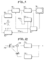
- the apparatus 10 conventionally comprises a source of radiation 30 , a detector 40 and a generator are Signau video 50.
- the combination of the detector and the video generator can include, for example, an amplifier of images associated with a television camera.
- the video signal from the generator 50 is applied to a noise reduction circuit 60, which can be a digital or digital noise reduction device of the type described in US Pat. No. 4,064,530, cited here simply for information.
- the video signals appearing at the output of the noise reduction assembly 60 are applied to a display device or to a “display” 70.
- the assembly 60 also delivers an output signal indicating movement, a signal which is applied to the processing circuit 100
- One of the outputs of the processing circuit 100 is connected to the intensity setting of the radiation source 30.
- a second output of the processing circuit 100 is brought back to the noise reduction assembly 60 and can be used, as is described below, for the adjustment of this assembly.
- a chronology or synchronization module 80 which includes the basic clock and which also delivers the synchronization signals in a conventional manner, is shown as being connected to the video generator 50, to the noise reduction assembly 60, to the display. 70 and to the processing circuit 100.
- FIG. 2 illustrates, in general , the operation of the digital noise which is the subject of US Pat. No. 4,064,530.
- a video input signal, arriving via a line 210, which has been normally digitalized, that is to say, transformed into binary pulses, (by means not shown) is applied, through a variable attenuator 212, to one of the terminals of an addition circuit 214.
- the output signal of the addition circuit 214 is applied to a delay circuit 216 which is calculated for produce a delay corresponding to the duration of a frame.
- the output signal of the delay circuit 216 is applied, through a chrominance inverter 218 and a variable attenuator 220, to the second input terminal of the addition circuit 214.
- the attenuators 212 and 214 are coupled, like the indicates the dashed line which joins them, in order to introduce respectively the transmission coefficients "(1-a)" and "a".
- a fraction (1-a) of the amplitude of the incident or "current" video signal is applied to one of the inputs of the addition circuit 214 and a fraction "a" of the amplitude of the "past" (or “delayed") video signal from the delay cricuit 216 is applied to the other input terminal of this circuit.
- the video output signal whose noise has been attenuated can be sampled at the output of the delay circuit 216, as shown, or at that of the addition circuit 214 or the chrominance inverter 218.
- a description of the operation of the inverter 218 is not necessary for a good understanding of the present invention and for more information the reader can, if necessary, refer to the aforementioned American patent n ° 4,064,530. It is quite obvious, moreover, that in the case of a black and white system, the chrominance reverser is useless.
- FIG. 3 is a block diagram of the assembly which fulfills the function of the addition circuit 214 and the attenuators 212 and 220 of FIG. 2, while also detecting the amount of movement of each picture element in order to adjust the attenuation coefficients.
- the "current" video signal received on line 210 is an eight bit binary coded signal (coded by means not shown) which is applied to an eight bit register 330.
- the delayed video signals, received through the chrominance inverter 218 (FIG. 2), are applied to another eight-bit register 232.
- a first step in this comparison consists in respectively applying the four least significant bits of the current video signal to the negative and positive input terminals of a differential amplifier 238. Assuming that the eight bits which represent the video level of the element image being considered is designated bit 0 (least significant) to bit 7 (most significant), the four bits referred to may be bits 1-4.
- the output signals from the differential amplifier 238 are applied to a comparator 240 which compares the output signals from the differential amplifier with a number of integration references (indicated at 242).
- the output signals of the integration comparator 240 are applied to a coefficient decoder 244 which has the function of generating the coefficient "a" which, as indicated above, determines the proportion of the amplitude of the video signal which must be added to the current video signal.
- the decoder 244 produces, according to the value of the particular difference produced by the integration comparator 240, one of the three values "a", namely: the fractions 1/4, 1/2 or 3/4. In the case of a relatively large difference at the output of the integration comparator 240, indicating the largest tolerable movement (ie, the largest movement for which noise reduction is still achieved), the coefficient " a "is 1/4.
- the decoder When the difference at the output of comparator 240 is smaller, indicating a lesser movement between the previous and current video signals, the decoder produces a coefficient "a" having the value 1/2. When the current motion detected is even smaller, a coefficient with the value 3/4 is produced.
- the coefficient "a”, in the form of a binary word, is applied to the addition circuit 246 which includes the elements 248 and 250, marked respectively "a” and "(1-a)", to indicate the respective fractions the amplitude of the previous and current video signals that are summed.
- the delayed video signal is applied to element 248, while the current video signal is applied to element 250.
- the comparator 270 produces a signal which is applied to the second input of the OR circuit 268, which thus produces a signal which, in turn, is applied to the multiplexer 254 in order to cause the return of the coefficient "a" to zero.
- the coefficient "a” returns to zero, thus causing the application of the current video signal alone to the output line 60a when (1) there is a difference between the three most significant bits. significant of the deferred and current video signals or (2) when Ir difference between the four least significant bits of the deferred and current video signals exceeds a preselected number designating the bypass threshold.
- the coefficient "a" is determined as explained above.
- FIG. 4 we see the block diagram of an embodiment of the processing circuits 100 of FIG. 1.
- These processing circuits include a programmable divider 110 which can, for example, be the model SN 7497 or SN 74167 manufactured by the American company Texas Instruments Corp.
- the divider of the division operation is adjustable by means of switches which can be actuated by the operator, via lines 110A. The operator thus selects an input number M which is used as the denominator in the division which, as will be seen, regulates the sensitivity in the present embodiment.
- the programmable divider 110 receives as input signal from line 60B the "bypass" signal from the digital noise reduction device 60 (of FIG. 3).
- the bypass signal is "active" when motion exceeding a certain threshold is detected in the particular picture element of the video frame.
- the bypass signal is "inactive".
- the programmable divider 110 also receives, by a line 110C the basic clock signal and by a reset line 110D, a amplitudes of these signals is applied by line 252 to one of the inputs of a multiplexer 254 which transmits a video signal whose noise has been attenuated on line 60a in cases where the value of the coefficient "a" is different from zero.
- Another circuit is also provided for bringing the value of the coefficient "a" to zero. More precisely, the output signals from the differential amplifier 238 are also called to a so-called “bypass" comparator 270 in which it is compared with a number (indicated in 272), representing the bypass threshold and which normally has a value. greater than the number of integration references. When the difference between the signal signal at the frame rate. These signals are supplied by the chronology or synchronization circuits 80 (FIG. 1). The basic clock signal includes clock pulses which appear at the rate of the individual picture elements in the video frame. The programmable divider 110 generates an output signal each time the bypass signal is "active" for at least a number M of clock pulses, where M is chosen by the operator.
- the output signal from the programmable divider 110 is connected to a digital or binary counter 120.
- This counter also receives by its delivery line, the signals transmitted at the frame rate of the synchronization circuit 80.
- the counter 120 contains a total which is substantially equal to the number of video elements which, at the last prescribed degree of movement have been found to be present (designated E) divided by the setting chosen by the operator, M, ie say, that it contains a total E / M.
- E the number of video elements which, at the last prescribed degree of movement have been found to be present
- M ie say, that it contains a total E / M.
- the output of the latch 130 is connected to a digital / analog converter 140, the output of which is, in turn, connected to a filter 150 having an adjustable time constant.
- the output of the filter 150 is connected, through a buffer amplifier 160, to the line 100a which, for its part, is connected to the control for adjusting the intensity of the radiation source 30 (FIG. 1).
- the output of the variable filter 150 is also connected to an analog / digital converter which is activated by signals having the frame rate.
- the output signals of the analog / digital converter 170 appearing on the line 100b are applied to the digital noise reduction device 60 and can be used, for example, as the number representing the bypass threshold 272 or as the integration reference number 242 ( Figure 3).
- the total amount of movement presented by an information frame (or a succession of frames, determined, for example, by the time constant of the filter circuit 150) is used to adjust the intensity of the source of X-rays and, if necessary, the feedback characteristics of the digital noise reduction.
- the bypass signal is active during an appreciable part of a frame
- the magnitude of the output signal from the counter 120 is relatively large at the end of the frame.
- a number of these frames results in a relatively high output signal on line 100a. This indicates an appreciable general movement of the body being represented and means that the noise reduction function is minimal on certain parts of the body image (as follows from the above description of the noise reduction system 60).
- a large signal on line 100a produces no attenuation of the X-ray source.
- a relatively small signal on line 100a indicates a relatively small overall movement of the various parts of the body being represented. Since this results in a significant attenuation of noise by the noise reduction system on most of the body being represented, (as explained above), the small signal of line 100a produces an attenuation of the radiation source, since a less intense source is necessary to obtain the desired signal / noise ratio.
- the signal of line 100a is applied in inverse ratio to the attenuation command of the radiation source 30.
- an accumulation of frames having appreciable movement is used to effectively reduce the feedback coefficient of the noise reduction system in the presence of a relatively large general or overall movement of the body in the image field.
- the reverse is also true in that a relatively small general movement of the body being represented results in an increase in the feedback coefficient of the noise reduction system.
- the time constant of the variable filter 150 determines the number of frames contributing to the determination of signals 100a and 100b. It is clear that, if necessary, different time constants could be used, for example, by providing several separate filters at the output of the digital / analog converter 140. One could also, if necessary, connect the output of the analog converter / digital 170 to line 100b via a fixed or "read-only" memory (not shown) used to provide programmed control of the noise reduction feedback action.
Landscapes
- Engineering & Computer Science (AREA)
- Multimedia (AREA)
- Signal Processing (AREA)
- Picture Signal Circuits (AREA)
- Transforming Light Signals Into Electric Signals (AREA)
Applications Claiming Priority (2)
| Application Number | Priority Date | Filing Date | Title |
|---|---|---|---|
| US220793 | 1980-12-29 | ||
| US06/220,793 US4409615A (en) | 1980-12-29 | 1980-12-29 | Video imaging with automatically controlled radiation source |
Publications (3)
| Publication Number | Publication Date |
|---|---|
| EP0055655A2 true EP0055655A2 (de) | 1982-07-07 |
| EP0055655A3 EP0055655A3 (en) | 1982-08-25 |
| EP0055655B1 EP0055655B1 (de) | 1984-09-19 |
Family
ID=22825005
Family Applications (1)
| Application Number | Title | Priority Date | Filing Date |
|---|---|---|---|
| EP81402005A Expired EP0055655B1 (de) | 1980-12-29 | 1981-12-15 | Verfahren und Vorrichtung, um mittels einer einstellbaren Strahlungsquelle einen beleuchteten Körper optisch darzustellen |
Country Status (3)
| Country | Link |
|---|---|
| US (1) | US4409615A (de) |
| EP (1) | EP0055655B1 (de) |
| DE (1) | DE3166211D1 (de) |
Cited By (2)
| Publication number | Priority date | Publication date | Assignee | Title |
|---|---|---|---|---|
| EP0102592A3 (en) * | 1982-08-27 | 1984-09-05 | Shimadzu Corporation | X-ray image producing system |
| EP0105619A3 (en) * | 1982-09-07 | 1987-08-26 | The Board Of Trustees Of The Leland Stanford Junior University | Multiple-measurement noise-reducing system |
Families Citing this family (12)
| Publication number | Priority date | Publication date | Assignee | Title |
|---|---|---|---|---|
| JPS5994045A (ja) * | 1982-11-22 | 1984-05-30 | Toshiba Corp | 画像入力装置 |
| JP2508078B2 (ja) * | 1987-04-30 | 1996-06-19 | 株式会社島津製作所 | X線画像処理装置 |
| US4878116A (en) * | 1988-06-02 | 1989-10-31 | Wayne State University | Vector lock-in imaging system |
| US5223932A (en) * | 1991-01-10 | 1993-06-29 | Wayne State University | Dynamic offset to increase the range of digitization of video images |
| US5917882A (en) * | 1996-11-29 | 1999-06-29 | Continental X-Ray Corporation | Radiographic/fluoroscopic imaging system with reduced patient dose and faster transitions between radiographic and fluoroscopic modes |
| US6766098B1 (en) * | 1999-12-30 | 2004-07-20 | Koninklijke Philip Electronics N.V. | Method and apparatus for detecting fast motion scenes |
| US8624980B2 (en) * | 2004-08-10 | 2014-01-07 | Thomson Licensing | Apparatus and method for indicating the detected degree of motion in video |
| US20070189455A1 (en) * | 2006-02-14 | 2007-08-16 | Accuray Incorporated | Adaptive x-ray control |
| US8092251B2 (en) * | 2007-12-29 | 2012-01-10 | Apple Inc. | Active electronic media device packaging |
| US9389419B2 (en) * | 2008-08-14 | 2016-07-12 | Honeywell International Inc. | Near-to-eye display artifact reduction system and method |
| CN102149321A (zh) | 2008-09-12 | 2011-08-10 | 艾可瑞公司 | 基于目标移动来控制x光成像 |
| JP6574957B2 (ja) * | 2017-09-29 | 2019-09-18 | 株式会社リガク | X線分析用信号処理装置及びx線分析用信号処理装置の調整方法 |
Family Cites Families (6)
| Publication number | Priority date | Publication date | Assignee | Title |
|---|---|---|---|---|
| DE1614580A1 (de) * | 1967-08-12 | 1970-11-05 | Siemens Ag | Roentgendiagnostikapparat |
| US3854049A (en) * | 1973-12-10 | 1974-12-10 | Wisconsin Alumni Res Found | Compensation for patient thickness variations in differential x-ray transmission imaging |
| US4240106A (en) * | 1976-10-14 | 1980-12-16 | Micro Consultants, Limited | Video noise reduction |
| US4064530A (en) * | 1976-11-10 | 1977-12-20 | Cbs Inc. | Noise reduction system for color television |
| US4162509A (en) * | 1978-06-21 | 1979-07-24 | The United States Of America As Represented By The Secretary Of The Army | Non-contact velocimeter using arrays |
| DE3007620C2 (de) * | 1980-02-28 | 1984-11-08 | Siemens AG, 1000 Berlin und 8000 München | Röntgendiagnostikeinrichtung mit einer Fernsehanlage mit bewegungsabhängiger Steuerung der Integrationszeit und Dosisleistung |
-
1980
- 1980-12-29 US US06/220,793 patent/US4409615A/en not_active Expired - Fee Related
-
1981
- 1981-12-15 EP EP81402005A patent/EP0055655B1/de not_active Expired
- 1981-12-15 DE DE8181402005T patent/DE3166211D1/de not_active Expired
Cited By (2)
| Publication number | Priority date | Publication date | Assignee | Title |
|---|---|---|---|---|
| EP0102592A3 (en) * | 1982-08-27 | 1984-09-05 | Shimadzu Corporation | X-ray image producing system |
| EP0105619A3 (en) * | 1982-09-07 | 1987-08-26 | The Board Of Trustees Of The Leland Stanford Junior University | Multiple-measurement noise-reducing system |
Also Published As
| Publication number | Publication date |
|---|---|
| DE3166211D1 (en) | 1984-10-25 |
| US4409615A (en) | 1983-10-11 |
| EP0055655B1 (de) | 1984-09-19 |
| EP0055655A3 (en) | 1982-08-25 |
Similar Documents
| Publication | Publication Date | Title |
|---|---|---|
| EP0055655B1 (de) | Verfahren und Vorrichtung, um mittels einer einstellbaren Strahlungsquelle einen beleuchteten Körper optisch darzustellen | |
| FR2550037A1 (fr) | Correction de defauts de cadrage automatique | |
| EP0145563A2 (de) | Katadioptrisches Abtast-Ophthalmoskop | |
| FR2575885A1 (fr) | Renforcateur de contraste pour images video | |
| FR2614711A1 (fr) | Procede et dispositif d'exploitation du signal d'ecran d'un ecran tactile | |
| EP0052024A1 (de) | Optoelektronische Anordnung für die videofrequente Bildanalyse durch Abtastung | |
| EP0751482B1 (de) | Verfahren und Vorrichtung zur temporären Rauschfilterung einer Bildfolge | |
| FR2829268A1 (fr) | Procede de traitement d'images pour angiographie soustractiv e numerisee | |
| EP0762145B1 (de) | Pulsverarbeitungssystem für einen Gammateilchen-CdTe-Strahlungsdetektor | |
| FR2575886A1 (fr) | Procede pour reduire la visibilite du bruit dans une suite d'images video et dispositif pour la mise en oeuvre de ce procede | |
| EP0093649A1 (de) | Verfahren zur röntgenologischen Bildverarbeitung für die Korrektur von durch Streustrahlung verursachten Bildfehlern | |
| FR2512545A1 (fr) | Procede et dispositif photometrique pour mesurer et regler l'epaisseur de couches a effet optique pendant leur formation sous vide | |
| EP0282106B1 (de) | System zur Synchronisierung auf einem halbdigitalen Signal | |
| EP0101336B1 (de) | Generator zur Verarbeitung eines Videosignals mit Kontrast für Strahlenkunde und Verfahren für derartige Signalverarbeitung | |
| FR2740558A1 (fr) | Procede de detection par designation laser et dispositif d'ecartometrie a detecteur matriciel correspondant | |
| EP1351498B1 (de) | Echtzeitverarbeitungsmethode eines Bildsignales | |
| EP0296011B1 (de) | Verfahren und Vorrichtung zur Bestimmung der Zahl der in einem bestimmten Raum anwesenden Personen | |
| EP0550586B1 (de) | Verfahren zur messung von rauschen in einem aktiven videobild | |
| FR2589302A1 (fr) | Systeme de thermographie infrarouge a sensibilite amelioree par accumulation progressive des lignes de l'image | |
| EP0419341B1 (de) | Videoempfangsausrüstung | |
| FR2629214A1 (fr) | Procede et systeme d'etalonnage d'un scanner a rayons x en utilisant un seul etalon non circulaire | |
| FR2547966A1 (fr) | Circuit numeriseur adaptatif pour un systeme de traitement d'information | |
| BE897838A (fr) | Procede pour augmenter a sensibilite d'une camera de television et systeme de television pour la mise en oeuvre de ce procede | |
| EP0542623A1 (de) | Verfahren und Vorrichtung zur Gewinnung und Verarbeitung von Durchleuchtungsbildern | |
| WO1998035244A1 (fr) | Dispositif d'acquisition sismique |
Legal Events
| Date | Code | Title | Description |
|---|---|---|---|
| PUAI | Public reference made under article 153(3) epc to a published international application that has entered the european phase |
Free format text: ORIGINAL CODE: 0009012 |
|
| PUAL | Search report despatched |
Free format text: ORIGINAL CODE: 0009013 |
|
| AK | Designated contracting states |
Designated state(s): DE FR IT NL |
|
| AK | Designated contracting states |
Designated state(s): DE FR IT NL |
|
| 17P | Request for examination filed |
Effective date: 19830126 |
|
| KL | Correction list |
Free format text: 83/03 ZEICHNUNG |
|
| ITF | It: translation for a ep patent filed | ||
| GRAA | (expected) grant |
Free format text: ORIGINAL CODE: 0009210 |
|
| AK | Designated contracting states |
Designated state(s): DE FR IT NL |
|
| REF | Corresponds to: |
Ref document number: 3166211 Country of ref document: DE Date of ref document: 19841025 |
|
| PLBI | Opposition filed |
Free format text: ORIGINAL CODE: 0009260 |
|
| 26 | Opposition filed |
Opponent name: SIEMENS AKTIENGESELLSCHAFT, BERLIN UND MUENCHEN Effective date: 19850614 |
|
| NLR1 | Nl: opposition has been filed with the epo |
Opponent name: SIEMENS AKTIENGESELLSCHAFT |
|
| PLBN | Opposition rejected |
Free format text: ORIGINAL CODE: 0009273 |
|
| STAA | Information on the status of an ep patent application or granted ep patent |
Free format text: STATUS: OPPOSITION REJECTED |
|
| 27O | Opposition rejected |
Effective date: 19881012 |
|
| NLR2 | Nl: decision of opposition | ||
| PGFP | Annual fee paid to national office [announced via postgrant information from national office to epo] |
Ref country code: FR Payment date: 19891124 Year of fee payment: 9 |
|
| PGFP | Annual fee paid to national office [announced via postgrant information from national office to epo] |
Ref country code: DE Payment date: 19891201 Year of fee payment: 9 |
|
| ITTA | It: last paid annual fee | ||
| PGFP | Annual fee paid to national office [announced via postgrant information from national office to epo] |
Ref country code: NL Payment date: 19891231 Year of fee payment: 9 |
|
| PG25 | Lapsed in a contracting state [announced via postgrant information from national office to epo] |
Ref country code: NL Effective date: 19910701 |
|
| NLV4 | Nl: lapsed or anulled due to non-payment of the annual fee | ||
| PG25 | Lapsed in a contracting state [announced via postgrant information from national office to epo] |
Ref country code: FR Effective date: 19910830 |
|
| PG25 | Lapsed in a contracting state [announced via postgrant information from national office to epo] |
Ref country code: DE Effective date: 19910903 |
|
| REG | Reference to a national code |
Ref country code: FR Ref legal event code: ST |