EP0055896B1 - Kreissäge - Google Patents
Kreissäge Download PDFInfo
- Publication number
- EP0055896B1 EP0055896B1 EP81305617A EP81305617A EP0055896B1 EP 0055896 B1 EP0055896 B1 EP 0055896B1 EP 81305617 A EP81305617 A EP 81305617A EP 81305617 A EP81305617 A EP 81305617A EP 0055896 B1 EP0055896 B1 EP 0055896B1
- Authority
- EP
- European Patent Office
- Prior art keywords
- saw
- compartment
- blade
- handle
- motor
- Prior art date
- Legal status (The legal status is an assumption and is not a legal conclusion. Google has not performed a legal analysis and makes no representation as to the accuracy of the status listed.)
- Expired
Links
Images



Classifications
-
- B—PERFORMING OPERATIONS; TRANSPORTING
- B23—MACHINE TOOLS; METAL-WORKING NOT OTHERWISE PROVIDED FOR
- B23D—PLANING; SLOTTING; SHEARING; BROACHING; SAWING; FILING; SCRAPING; LIKE OPERATIONS FOR WORKING METAL BY REMOVING MATERIAL, NOT OTHERWISE PROVIDED FOR
- B23D59/00—Accessories specially designed for sawing machines or sawing devices
- B23D59/006—Accessories specially designed for sawing machines or sawing devices for removing or collecting chips
- B23D59/0064—Accessories specially designed for sawing machines or sawing devices for removing or collecting chips by suction
-
- B—PERFORMING OPERATIONS; TRANSPORTING
- B23—MACHINE TOOLS; METAL-WORKING NOT OTHERWISE PROVIDED FOR
- B23Q—DETAILS, COMPONENTS, OR ACCESSORIES FOR MACHINE TOOLS, e.g. ARRANGEMENTS FOR COPYING OR CONTROLLING; MACHINE TOOLS IN GENERAL CHARACTERISED BY THE CONSTRUCTION OF PARTICULAR DETAILS OR COMPONENTS; COMBINATIONS OR ASSOCIATIONS OF METAL-WORKING MACHINES, NOT DIRECTED TO A PARTICULAR RESULT
- B23Q11/00—Accessories fitted to machine tools for keeping tools or parts of the machine in good working condition or for cooling work; Safety devices specially combined with or arranged in, or specially adapted for use in connection with, machine tools
- B23Q11/0042—Devices for removing chips
- B23Q11/0046—Devices for removing chips by sucking
-
- B—PERFORMING OPERATIONS; TRANSPORTING
- B27—WORKING OR PRESERVING WOOD OR SIMILAR MATERIAL; NAILING OR STAPLING MACHINES IN GENERAL
- B27B—SAWS FOR WOOD OR SIMILAR MATERIAL; COMPONENTS OR ACCESSORIES THEREFOR
- B27B9/00—Portable power-driven circular saws for manual operation
-
- Y—GENERAL TAGGING OF NEW TECHNOLOGICAL DEVELOPMENTS; GENERAL TAGGING OF CROSS-SECTIONAL TECHNOLOGIES SPANNING OVER SEVERAL SECTIONS OF THE IPC; TECHNICAL SUBJECTS COVERED BY FORMER USPC CROSS-REFERENCE ART COLLECTIONS [XRACs] AND DIGESTS
- Y10—TECHNICAL SUBJECTS COVERED BY FORMER USPC
- Y10T—TECHNICAL SUBJECTS COVERED BY FORMER US CLASSIFICATION
- Y10T83/00—Cutting
- Y10T83/869—Means to drive or to guide tool
- Y10T83/8763—Convertible from tool path to another or from implement to machine
Definitions
- the present invention relates to portable circular saws, and more particularly to improvements in the housing structure thereof.
- Circular saws with two handles are known as shown in U.S. Patent 180,815, and still other arrangements are known wherein a handle is in line with the circular saw-blade as shown in U.S. Patent 963,520.
- German Offenlegungs- schrift 27 54 186 discloses a portable circular saw having a dust removal system in which one end of the dust bag is connected via a short conduit to the saw-blade compartment forwardly of the motor compartment, and the other end of the dust bag is connected via a longer special conduit to the outer end of the motor compartment containing the fan.
- German Published Patent Application 7411811 discloses a portable electric saw having a dust removal system with the fan mounted in the outer end of the motor compartment and arranged to draw dust from the saw-blade compartment through a passage specially formed in the motor housing; the dust is then discharged forwardly through a nozzle into a dust bag located in the forward direction ahead of the saw.
- dust conduits have to be specially provided; also, the dust bags limit some of the operator's forward view of the workpiece being cut. Further, the saws are not adapted for ease of operation and versatility.
- the present invention is concerned with improving the housing structure of portable circular saws to enable the saws to be more efficiently manufactured and assembled, and yet provide the basis for incorporating many specialized features, such as dust removal, ease of operation, and versatility.
- a portable circular saw having an improved housing which permits the incorporation therein of at least part of a dust removal system in an improved manner.
- the main object of the present invention is the construction of the circular saw housing from three housing parts which conjointly form the forward and rear handles, the motor compartment, and the saw-blade compartment. This has the advantage of facilitating ease of assembly, including the dust removal system.
- a further object of the invention is the provision of a forward hollow handle providing a passage- way in communication with the saw-blade compartment and through which passageway sawdust can be removed.
- a preferred feature of the invention is the provision of a rear handle in line with the saw-blade so that, in conjunction with the arrangement of the forward handle, the saw, when gripped by an operator, is balanced about the motor compartment.
- a portable circular saw or the like comprising: a saw-blade compartment for accommodating a circular saw-blade; a motor compartment secured to the saw blade compartment and projecting transversely therefrom, a motor in the motor compartment for driving the saw-blade; a rear handle extending rearwardly from the saw-blade compartment; a forward handle connected to the saw blade compartment and projecting transversely therefrom on the same side thereof as the motor compartment, the forward handle being hollow and defining a passageway therein which is in communication with the interior of the saw-blade compartment and which is also adapted to be connected to a vacuum system, whereby the forward handle forms part of a dust removal.
- the saw-blade compartment, the motor compartment, the rear handle and the forward handle being formed from three separate housing parts, the first of said housing parts forming one side of said rear handle, and a portion of said saw-blade compartment; the second of said housing parts forming the other side of said rear handle, a portion of said motor compartment, another portion of said saw-blade compartment, and a portion of said forward handle, said first and second housing parts abutting each other; and the third of said housing parts forming the remainder of said motor compartment, the remainder of said forward handle and the remainder of said saw-blade compartment, said third and first housing parts abutting each other and said third housing part abutting said second housing part along a plane transverse to the plane of rotation of the circular saw blade.
- a strut preferably connects the forward handle to the motor compartment at a location spaced from the saw-blade compartment thereby defining a closed handle.
- a fan may be mounted in the motor compartment with one end of the passageway in the forward handle being in communication with the fan, whereby sawdust generated in the saw-blade compartment is drawn by the fan through the. passageway and discharged.
- the sawdust may be withdrawn through the passageway, or part thereof, by connecting an external source of vacuum to the passageway; a deflector member may be at least partially disposed in the passageway and be movable between first and second positions to enable the sawdust to be withdrawn from either end of the passageway and discharged to either side of the saw.
- Fig. 1 depicts a portable circular saw having a circular saw-blade 2 detachably secured to a drive shaft 4 in known manner.
- the lower portion of the blade 2 is shielded by a pivoted retractable cover 6 in known manner.
- the operational components of the circular saw are contained in a housing 8 which also serves to shield the upper portion of the blade 2.
- the housing 8 is formed with a rear closed handle 10 rearwardly from which extends an electric cable 12.
- An on/off trigger switch 14 is provided in the upper part of the closed handle 10 which is shaped to enable the handle 10 to be conveniently and securely gripped by an operator's right hand.
- Mounted below housing 8 is a base plate 16 for engaging and sliding on any workpiece to be cut.
- the complete righthand side of the housing 8 is formed by a first housing part 18 molded from plastics material and having a port 20 therein.
- Fig. 2 depicts the lefthand side of the circular saw and shows a motor compartment 22 and a forward closed handle 24 which is hollow and has a passageway 26 therethrough which registers with the port 20 in Fig. 1.
- the upper surface 28 of the casing 8 is flat and in a plane at right angles to that of the saw-blade 2.
- the extreme upper surface portion 30 of the forward handle 24 is in the same plane as the surface 28.
- the complete lefthand side of the housing 8 is formed by a second housing part 32 and a third housing part 34, both molded from plastics material.
- the second housing part 32 forms one side of the rear handle 10, the rear half of the forward handle 24, the rear half of the motor compartment 22, and a portion of the lefthand side of a compartment 39 containing the saw-blade 2.
- the third housing part 34 forms the forward half of the forward handle 24, the forward half of the motor compartment 22, and a portion of the saw-blade compartment 39.
- the forward handle 24 is disposed adjacent the front of the circular saw and forward of the central axis of the motor compartment 22.
- the second and third housing parts 32, 34 abut each other in a plane and form a joint 36 between the halves of the motor compartment 22 and the two halves of the forward handle 24.
- the plane of the joint 36 is at right angles to that of the saw-blade 2 and is inclined forwardly of the plane containing the surfaces 28 and 30 at an angle of 60 degrees.
- the second and third housing parts 32, 34 are secured to the first housing part 18 by seven screws 37.
- the base plate 16 has a mechanism 38 for adjusting its position relative to the casing 8 for adjusting the depth of cut that can be made by the saw-blade 2, and also has a mechanism 40 for adjusting the position of the base plate 16 to determine the angle of cut that can be made.
- a depressable button 42 enables the trigger switch 14 to be releasably locked in the "on" position during operation.
- Fig. 3 more clearly shows the forward closed handle 24 and its integral connection to the motor compartment 22.
- the flat upper surface 28 of the housing 8 is also more clearly shown.
- the first and second housing parts 18, 32 abut each other in a plane and form a joint 44 which lies in the plane of rotation of the saw-blade 2.
- the joint 44 equally divides the rear handle 10 and the saw-blade compartment in the longitudinal direction and is in the plane of rotation of the saw-blade 2.
- Fig. 4 shows the three housing parts 18, 32, 34 forming the housing 8 with all other components omitted.
- the closed handle 24 has a grip portion 46, which is at right angles to the first housing part 18, and a strut-like portion connecting the grip portion 46 to the outer end of the motor compartment 22.
- the first and third housing parts 18, 34 abut in a joint 48 which is in line with the joint 44.
- the second and third housing parts 32, 34 are secured to each other by screws 49, two of which can be seen in Fig. 4.
- the housing 8 by manufacturing the housing 8 from only three parts 18, 32, 34, which are arranged to fit together as described above, the circular saw can be more easily and simply assembled.
- the motor (to be described later) can be placed in one of the motor compartment halves and then clamped therein, in clamshell fashion, by securing the other motor compartment half.
- the first housing part 18 can be positioned and secured last, so leaving the housing completely open on one side during assembly and allowing easy access for making wiring connections and installation of other internal components.
- a sturdy housing 8 is produced. This construction allows the three housing parts to be molded from suitable plastics material so reducing further the cost of manufacture and also making possible the production of a lighter weight, portable circular saw.
- the saw By having the rear closed handle 10 in line with the saw-blade 2, together with the forward closed handle 24 adjacent the top of the circular saw and forward of the motor compartment 22, and so forward of the saw-blade drive shaft 4, the saw can more easily and accurately be controlled by an operator. This is of particular importance when the operator is trying to accurately cut in a straight line. It should be noted that by having the two handles so arranged with the motor compartment 22 between them, and with the forward handle extending outwardly virtually for the length of the elongated motor compartment, the saw, when gripped by the operator, is balanced about the motor compartment 22.
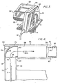
- Fig. 5 depicts diagrammatically the circular saw described above arranged to be used as a table saw.
- the circular saw is turned upside down from its normal operating position and placed on a corner of a suitable workbench or table 50.
- the grip portion of the forward handle is located adjacent and parallel to the front edge 52 of the table 50.
- the first housing part 18 is placed adjacent a side edge (not shown) of the table 50. Due to the flat surface 28 and the upper surface 30 of the forward handle 24 being in a common plane (see Figs. 2 and 3), which is parallel to the normal operating position of the base plate 16, the circular saw rests safely on the table 50.
- the stability of the circular saw in this position is enhanced by the length, position, and construction of the forward closed handle 24, the right angle relationship of the forward handle 24 to the plane of rotation of the saw-blade 2, and the width and length of the flat surface 28.
- the grip portion of the forward handle is now clamped securely to the table 52 by an adjustable clamp 54.
- the rear closed handle 10 is also clamped securely to the table 52 by another clamp 56, without interfering with the trigger switch 14.
- the saw With the base plate 16 set as shown, the saw is started with the blade rotating in the direction of the arrow 58, and a workpiece 60 to be cut is fed on the base plate 16 in the direction of the arrow 62.
- the pivoted blade cover 6 has been omitted in Fig. 5. In normal operation the cover 6 would be pivoted to the left in Fig. 5 by the workpiece 60 as it passes by the rotating saw-blade 58.
- Fig. 5 the electric motor 64, which is contained in the motor compartment-22, is shown schematically by a broken line.
- the motor 64 is contacted by inner wall portions of the two halves of the motor compartment 22 in clamshell fashion.
- the axis of rotation of the saw-blade 2 is marked at 66.
- the motor 64 drives the saw-blade shaft through gearing (not shown) partially housed in a compartment 68 which is an extension of the motor compartment 22.
- Fig. 6 depicts a modification of the circular saw and shows the passageway 26 having an opening 70 adjacent the port 20.
- the opening 70 is partly formed in the first housing part 18 and partly formed in the second housing part 32.
- the third housing part 34 completes the formation of the opening 70, although this cannot be seen in Fig. 6.
- the opening 70 enables the passageway 26 to communicate with the interior 72 of the blade compartment 39 housing the saw-blade 2.
- a deflector member 74 is a close slidable fit in the port 20 and the passageway 26.
- the member 74 is formed from a sleeve 75 having one end closed by a curved wall 76, and the other end 77 open.
- An orifice 79 through the side wall of the sleeve 75 intermediate its ends registers with the opening 70.
- the passageway 26 has a cross section which is not completely circular.
- the port 20 has the same cross section.
- the exterior surface of the sleeve 75 also has the same cross-sectional shape to prevent rotation of the sleeve 75 relative to the passageway 26 so ensuring continuous registering of the orifice 79 and the opening 70.
- the outermost part of the handgrip 46 (to the right in Fig. 6) is provided with a socket 78, the outer edge 80 of which is disposed in a substantially vertical plane.
- the socket 78 is adapted to releasably receive a hose adaptor 82 having a hose 84 of a vacuum system attached thereto.
- the hose 84 is connected to a source of vacuum (not shown). Sawdust thrown up in the interior 72 of the blade compartment 39 by the action of the rotating blade 2 is sucked by the vacuum source, together with air, through the opening 70 and via the deflector member 74 through the passageway 26 in the grip portion 46 of the forward handle 24, as indicated by the arrow 82a. The sawdust and air exit from the passageway 26 and are drawn away through the hose 84 to a sawdust receptacle (not shown).
- Fig. 7 shows another position of the deflector member 74 when it is desired to discharge the sawdust on the opposite side of the circular saw. From the position shown in Fig. 6, the deflector member 74 is slidably withdrawn, axially reversed, and then slidably inserted, closed end first, into the port 20 and passageway 26 until the orifice 79 registers with the opening 70. The hose adaptor 82 is then withdrawn from the socket 78 and inserted in the open end 77 of the member 74, with the vacuum hose 84 now discharging to the opposite side of the saw.
- the sawdust and air are drawn by the vacuum source through the opening 70, the deflector member 74, and the hose adaptor 82 as indicated by the arrow 86, i.e., out of the righthand side of the circular saw as viewed in Fig. 3.
- the operator can determine on which side of the circular saw the sawdust should be discharged.
- the forward handle 24 serving two functions, that of a handle and that of part of the dust removal system. Also, with the position of the forward handle 24 being at the top of the saw and forward of the motor compartment 22, the vacuum hose 84 extends from either side of the saw in a position that does not interfere with the operator's grip of either handle 24 or 10 nor with the operator's view of the workpiece and the cut being made.
- communication of the passageway 26 with the interior 72 of the saw-blade compartment at a location forward of the axis of the rotation of the saw-blade 2 aids more complete removal of the dust by the vacuum source in conjunction with the action of the saw-blade 2 which still has substantial upward component of movement approaching and adjacent that location.
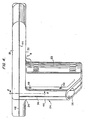
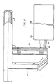
- Figs 8, 9, and 10 depict the preferred embodiment of the portable circular saw.
- This embodiment is the same as that described in relation to Figs. 1 through 5 except for two features.
- the saw housing has three parts 18, 32, and 34 as before which conjointly between them form the forward closed handle 24, the rear closed handle 10, the motor compartment 22, and the saw-blade compartment 39.
- the forward handle is hollow and has a passageway 90 formed therein. However, the passageway is not open to the exterior of the saw at its ends.
- passageway 90 communicates at one end with the interior 72 of the saw-blade compartment 39 via an opening 92. At the other end, passageway 90 extends through a downward arm or strut 94 of the closed handle 24 and communicates with an inlet 96 of a fan compartment 98 in the motor compartment 22.
- the electric motor 64 in the compartment 22 is drivingly connected at its inner end to the saw-blade 2 through gearing 100, with a motor cooling fan 102 mounted on armature shaft 104 between the motor 64 and the gearing 100.
- the armature shaft 104 extends through a bearing 106, in a bearing housing 108, terminating in the fan compartment 98 in which is housed a centrifugal fan impeller 110 mounted on that end of the shaft 104 and closely fitting in the fan compartment98.
- the housing part 18 does not have the port 20 therein shown in Fig. 1.
- the fan compartment communicates with a rearwardly extending nozzle 112 over which is attached the neck 114 of a dust bag 116, part of the length of bag 116 being omitted at 118.
- the nozzle 112 is located at the outward end of the motor compartment 22 with the dust bag 116 spaced a convenient distance from the rear closed handle 10.
- the motor 64 rotates the centrifugal fan 110 to draw sawdust and air from the interior 72 of the blade compartment 39, through the passageway 90, into the fan 110 which then discharges the dust and air into the dust bag 116 which retains the dust, the air escaping through the bag 116.
- This flow of air and dust is indicated by arrows 120 in Figs. 8 and 9.
- the hollow forward handle again serves the dual functions of a handle and part of a dust removal system, and it should be noted that all of the passageways and compartments of the dust removal system are formed by the three housing parts 18, 32, and 34, with the housing parts 32 and 34 conjointly forming the passageway 90 and fan compartment 98. Again, this dust removal system, due to the utilization of the forward handle 24, does not interfere with an operator's grasp of the two handles 24 and 10, nor his sight of the workpiece being cut.
- any tendency for the dust bag to effect a turning moment lengthwise of the saw can be readily compensated by the thrust of the operator on the forward handle 24; this is further helped by the arrangement of the forward and rear handles causing the saw to be balanced about the motor compartment.
- Fig. 8 In Fig. 8 are shown two bores 122 in the housing part 32. These bores extend through housing part 18 and have walls (not shown) which separate them from the interior 72 of the blade compartment 39. These bores are adapted to receive straight rod-like legs of clamps.
- this embodiment When this embodiment is to be used in the inverted position as a table saw, it is readily and safely clamped to a bench top by using clamps having a straight rod-like clamping arm, inserting the straight arms through the bores 122, and tightening the clamps on the underside of the bench top.
Landscapes
- Engineering & Computer Science (AREA)
- Mechanical Engineering (AREA)
- Life Sciences & Earth Sciences (AREA)
- Wood Science & Technology (AREA)
- Forests & Forestry (AREA)
- Sawing (AREA)
- Polishing Bodies And Polishing Tools (AREA)
- Stringed Musical Instruments (AREA)
Claims (10)
Priority Applications (1)
| Application Number | Priority Date | Filing Date | Title |
|---|---|---|---|
| AT81305617T ATE18734T1 (de) | 1980-12-11 | 1981-11-27 | Kreissaege. |
Applications Claiming Priority (2)
| Application Number | Priority Date | Filing Date | Title |
|---|---|---|---|
| GB8039712 | 1980-12-11 | ||
| GB8039712 | 1980-12-11 |
Publications (3)
| Publication Number | Publication Date |
|---|---|
| EP0055896A2 EP0055896A2 (de) | 1982-07-14 |
| EP0055896A3 EP0055896A3 (en) | 1983-08-17 |
| EP0055896B1 true EP0055896B1 (de) | 1986-03-26 |
Family
ID=10517913
Family Applications (1)
| Application Number | Title | Priority Date | Filing Date |
|---|---|---|---|
| EP81305617A Expired EP0055896B1 (de) | 1980-12-11 | 1981-11-27 | Kreissäge |
Country Status (4)
| Country | Link |
|---|---|
| US (1) | US4414743A (de) |
| EP (1) | EP0055896B1 (de) |
| AT (1) | ATE18734T1 (de) |
| DE (1) | DE3174215D1 (de) |
Cited By (1)
| Publication number | Priority date | Publication date | Assignee | Title |
|---|---|---|---|---|
| USD489591S1 (en) | 2002-10-01 | 2004-05-11 | Milwaukee Electric Tool Corporation | Circular saw |
Families Citing this family (55)
| Publication number | Priority date | Publication date | Assignee | Title |
|---|---|---|---|---|
| US4608477A (en) * | 1983-03-08 | 1986-08-26 | The United States Of America As Represented By The United States Department Of Energy | Electric arc saw apparatus |
| US4675999A (en) * | 1984-11-16 | 1987-06-30 | Hitachi Koki Company, Ltd. | Portable power tool equipped with dust collector |
| DE3660988D1 (en) * | 1985-01-18 | 1988-12-01 | Guido Valentini | Portable electrical milling and/or trimming machine tool for the machining with suction of produced chips and dust |
| DE3615736A1 (de) * | 1986-05-09 | 1987-11-12 | Festo Kg | Kreissaege, insbesondere handkreissaege |
| US4856394A (en) * | 1988-04-14 | 1989-08-15 | Porter-Cable Corporation | Portable circular saw |
| JPH0236097A (ja) * | 1988-07-26 | 1990-02-06 | Koumu:Kk | コンクリート等用のエアーカツター |
| DE3843236A1 (de) * | 1988-12-22 | 1990-06-28 | Bosch Gmbh Robert | Handkreissaege |
| US5088197A (en) * | 1989-01-06 | 1992-02-18 | Pro Power Corporation | Power-driven chain saw |
| US5074044A (en) * | 1991-04-26 | 1991-12-24 | Duncan C Warren | Dust disposal attachment for a rotary element of a power tool |
| US5159759A (en) * | 1991-06-26 | 1992-11-03 | Fringer Daniel L | Debris shield for a hand held power saw |
| US6427570B1 (en) | 1991-10-09 | 2002-08-06 | Black & Decker Inc. | Dust collection system for compound miter saw |
| US5819619A (en) * | 1991-10-09 | 1998-10-13 | Black & Decker Inc. | Dust collection system for compound miter saw |
| US6899005B1 (en) | 1991-10-09 | 2005-05-31 | Black & Decker Inc. | Adjustable fence for compound miter saw |
| EP0558253A1 (de) * | 1992-02-28 | 1993-09-01 | Black & Decker Inc. | Staubsammeln |
| US5235753A (en) * | 1992-03-20 | 1993-08-17 | Black & Decker Inc. | Circular saw lower guard chip deflector |
| DE4393469T1 (de) * | 1992-07-28 | 1994-10-20 | Matsushita Electric Works Ltd | Schneidverfahren und Sägewerkzeug |
| US5327649A (en) * | 1993-02-11 | 1994-07-12 | Skinner Christopher L | Circular saw with dust collector |
| US5588213A (en) * | 1995-03-07 | 1996-12-31 | Swanberg; Alan M. | Circular saw with dust trapper |
| DE19512262C2 (de) * | 1995-03-24 | 2003-07-31 | Black & Decker Inc | Handgeführter, motorgetriebener Hobel |
| JP3214295B2 (ja) * | 1995-05-12 | 2001-10-02 | 日立工機株式会社 | 携帯用集じん丸のこ |
| US5878607A (en) * | 1995-07-06 | 1999-03-09 | Johnson & Johnson Professional, Inc. | Surgical cast cutter |
| US5737843A (en) * | 1996-10-03 | 1998-04-14 | Fringer; Morris A. | Universal devices for protecting the user of a circular saw from flying debris |
| US5850698A (en) * | 1997-05-30 | 1998-12-22 | Black & Decker Inc. | Portable circular saw |
| US6219922B1 (en) * | 1997-06-04 | 2001-04-24 | Black & Decker, Inc. | Nozzle assembly for a power tool |
| JP3404517B2 (ja) * | 1997-06-19 | 2003-05-12 | 株式会社マキタ | テーブルソー |
| US5884544A (en) * | 1997-11-18 | 1999-03-23 | Emerson Electric Co. | Scroll saw vacuum attachment assembly |
| US6145555A (en) * | 1998-03-04 | 2000-11-14 | O'neill; John D. | Cutting tool and method of use for catching chips and debris during turning operations |
| US6470778B1 (en) | 1998-05-20 | 2002-10-29 | Black & Decker Inc. | Dust collector for a power tool |
| FR2782288A1 (fr) * | 1998-08-14 | 2000-02-18 | Milwaukee Electric Tool Corp | Scie circulaire amelioree. |
| US6318352B1 (en) * | 2000-05-15 | 2001-11-20 | Michael Gnazzo | Dust and particle control attachment for a saw |
| US7509900B2 (en) * | 2001-02-20 | 2009-03-31 | Young Ronald E | Scroll saw with dust collector |
| DE10131266A1 (de) * | 2001-06-29 | 2003-01-09 | Bosch Gmbh Robert | Handschleifmaschine |
| US6827640B2 (en) * | 2002-03-01 | 2004-12-07 | S&G Company, Llc | Portable dust collection system |
| US7581323B2 (en) * | 2002-09-17 | 2009-09-01 | Credo Technology Corporation | Cordless circular saw |
| US20040060178A1 (en) * | 2002-10-01 | 2004-04-01 | Mark Willer | Circular saw |
| DE50306834D1 (de) * | 2002-11-22 | 2007-05-03 | Bosch Gmbh Robert | Elektrohandwerkzeugmaschine |
| DE50309102D1 (de) * | 2002-11-22 | 2008-03-20 | Bosch Gmbh Robert | Elektrohandkreissägemaschine |
| NL1022807C2 (nl) * | 2003-02-28 | 2004-08-31 | Bosch Gmbh Robert | Schaafmachine met verbeterde spaanafvoer. |
| US8322040B2 (en) * | 2003-05-23 | 2012-12-04 | Exceptional Ip Holdings Llc | Handle including two handgrips and/or a hand alignment mechanism |
| US7174822B2 (en) * | 2004-01-13 | 2007-02-13 | Edgecraft Corporation | Efficient food slicer |
| DE102004004003A1 (de) * | 2004-01-27 | 2005-08-11 | Robert Bosch Gmbh | Spanauffangbehälter sowie System aus einem Spanauffangbehälter und einer Schutzhaube für eine Werkzeugmaschine |
| WO2005118195A2 (en) * | 2004-05-28 | 2005-12-15 | Scientific Molding Corporation Ltd. | Hand-held circular saw, in particular plunge-cut saw |
| US20070044609A1 (en) * | 2005-08-30 | 2007-03-01 | Brazell Kenneth M | Motor driven wood working tool with vacuum feature |
| US20080276773A1 (en) * | 2006-03-30 | 2008-11-13 | Radhakrishna Shesha Iyengar Togare | Multipurpose cutting method for cutting various materials |
| US7310879B1 (en) | 2006-07-27 | 2007-12-25 | Robert Bosch Gmbh | Cutting attachment having an adjustable foot for rotary hand tools |
| US7596872B2 (en) * | 2006-07-27 | 2009-10-06 | Robert Bosch Gmbh | Cutting attachment with a removable cover for rotary hand tools |
| DE102006061623A1 (de) * | 2006-12-27 | 2008-07-03 | Robert Bosch Gmbh | Handwerkzeugmaschine |
| US20100058911A1 (en) * | 2008-09-11 | 2010-03-11 | Jay Aaron Goddard | Blade Guard for Power Tool Having an Evacuation System |
| JP5649834B2 (ja) * | 2010-03-04 | 2015-01-07 | 株式会社マキタ | 手持ち式切断工具 |
| JP5468420B2 (ja) * | 2010-03-04 | 2014-04-09 | 株式会社マキタ | 手持ち式切断工具 |
| JP2014148006A (ja) * | 2013-02-01 | 2014-08-21 | Makita Corp | 電動工具及び携帯用マルノコ |
| US9616557B2 (en) | 2013-03-14 | 2017-04-11 | Black & Decker Inc. | Nosepiece and magazine for power screwdriver |
| US10722960B2 (en) * | 2017-02-22 | 2020-07-28 | Makita Corporation | Cutting device |
| JP7210226B2 (ja) * | 2018-11-02 | 2023-01-23 | 株式会社マキタ | 携帯用切断機 |
| JP7586181B2 (ja) * | 2020-08-31 | 2024-11-19 | 工機ホールディングス株式会社 | 作業機 |
Family Cites Families (23)
| Publication number | Priority date | Publication date | Assignee | Title |
|---|---|---|---|---|
| DE7411811U (de) | 1974-07-04 | Scheer C & Cie | Elektret-Handkreissäge | |
| US180815A (en) * | 1876-08-08 | Improvement in machines for making barrels | ||
| US963520A (en) * | 1909-07-14 | 1910-07-05 | John W Costello | Saw. |
| US1175963A (en) * | 1914-09-28 | 1916-03-21 | Joseph Loeser | Saw. |
| US1644432A (en) * | 1925-01-05 | 1927-10-04 | Harry W Howland | Combination portable electric saw and drill |
| DE498645C (de) * | 1929-02-14 | 1930-05-24 | Gustav Flebbe | Vorrichtung zur Herstellung von Nuten, Rillen oder aehnlichen Vertiefungen in Steinen, Mauerwerk o. dgl. |
| US1737552A (en) * | 1929-05-07 | 1929-12-03 | Altman Clay | Device for removing plaster-of-paris casts from the human body |
| US1888679A (en) * | 1931-01-07 | 1932-11-22 | Walt Products Corp De | Safety device for cutting machines |
| US1900553A (en) * | 1931-02-04 | 1933-03-07 | Syntron Co | Portable motor driven saw |
| DE967413C (de) * | 1948-10-02 | 1957-11-07 | Festo Maschf Stoll G | Elektromotorisch angetriebene Handkreissaege |
| GB786701A (en) * | 1955-03-02 | 1957-11-20 | G M F Electric Motors Pty Ltd | Improvements in or relating to portable sawing tools |
| FR1231379A (fr) * | 1959-02-18 | 1960-09-28 | Machine portative à couper et à meuler, équipée d'un capot de protection et de patins de guidage | |
| US3128802A (en) * | 1962-04-05 | 1964-04-14 | John V Hostetter | Portable power saw with tiltable face plate |
| US3245439A (en) * | 1964-06-03 | 1966-04-12 | Black & Decker Mfg Co | Portable electric saw and switch mounting means therefor |
| US3456696A (en) * | 1966-07-13 | 1969-07-22 | Rockwell Mfg Co | Portable circular saw |
| DE1301975B (de) * | 1968-03-01 | 1969-08-28 | Licentia Gmbh | Elektromotorisch angetriebenes Handwerkzeug |
| US3583106A (en) * | 1969-04-02 | 1971-06-08 | Gunther H W Dobbertin | Portable cutting tool |
| DE2133308C3 (de) * | 1971-07-05 | 1980-03-27 | Eugen Lutz Gmbh U. Co Maschinenfabrik, 7130 Muehlacker | Elektrische Handkreissäge |
| AT341751B (de) * | 1972-10-24 | 1978-02-27 | Mey Kg Maschf Mafell | Handkreissage |
| DE7407412U (de) * | 1974-03-02 | 1975-01-16 | Festo Maschinenfabrik Gottlieb Stol | Handkreissäge |
| US4051880A (en) * | 1976-10-29 | 1977-10-04 | The Singer Company | Dustless routers |
| DE2754186A1 (de) * | 1977-12-06 | 1979-06-07 | Licentia Gmbh | Handkreissaege mit einer in der schutzhaube der saege angebrachten spanauswurfoeffnung |
| US4241505A (en) * | 1979-05-21 | 1980-12-30 | Johns-Manville Corporation | Dust shroud for portable circular saw |
-
1981
- 1981-11-27 EP EP81305617A patent/EP0055896B1/de not_active Expired
- 1981-11-27 AT AT81305617T patent/ATE18734T1/de not_active IP Right Cessation
- 1981-11-27 DE DE8181305617T patent/DE3174215D1/de not_active Expired
- 1981-12-10 US US06/329,218 patent/US4414743A/en not_active Expired - Lifetime
Cited By (2)
| Publication number | Priority date | Publication date | Assignee | Title |
|---|---|---|---|---|
| USD489591S1 (en) | 2002-10-01 | 2004-05-11 | Milwaukee Electric Tool Corporation | Circular saw |
| USD489954S1 (en) | 2002-10-01 | 2004-05-18 | Milwaukee Electric Tool Corporation | Latch of a circular saw |
Also Published As
| Publication number | Publication date |
|---|---|
| US4414743A (en) | 1983-11-15 |
| EP0055896A3 (en) | 1983-08-17 |
| ATE18734T1 (de) | 1986-04-15 |
| DE3174215D1 (en) | 1986-04-30 |
| EP0055896A2 (de) | 1982-07-14 |
Similar Documents
| Publication | Publication Date | Title |
|---|---|---|
| EP0055896B1 (de) | Kreissäge | |
| US4051880A (en) | Dustless routers | |
| US6289956B1 (en) | Wood planer attachment for directing and capturing wood shavings and chips | |
| EP3388177B1 (de) | Handschneidwerkzeug | |
| US4422239A (en) | Powered handtool | |
| US7356930B2 (en) | Method and apparatus for removing dust from a workpiece | |
| CN100446936C (zh) | 手持式电动工具机 | |
| US20190329440A1 (en) | Portable Power Tool | |
| US4932126A (en) | Hand held trimmer for cutting vegetation such as hedges and the like | |
| US6651710B2 (en) | Dust-sucking and power-driving motor | |
| US12459157B2 (en) | Mobile hand-held sawing machine having pre-cutting assembly and grip | |
| JP7686577B2 (ja) | 筋目入れユニットと工具交換を備えた可搬型手持ち鋸機 | |
| US3902284A (en) | Low profile blower assembly for portable belt sanders | |
| US5758702A (en) | Router saw and guide | |
| US7740523B2 (en) | Portable power tool with a guide channel | |
| US6173499B1 (en) | Vent cover for an electric saw | |
| US2553924A (en) | Power saw and sander | |
| CN1974093B (zh) | 具有用于从工件去除碎屑的装置的动力工具 | |
| US7207874B2 (en) | Electric hand power tool | |
| EP0221652B1 (de) | Motorisch getriebenes Werkzeug | |
| CN114786853B (zh) | 具有在纵向侧处的预先划刻工具的可移动的手持式锯切机器 | |
| GB2111192A (en) | Power tools | |
| US12275073B2 (en) | Mobile hand-held machine saw with scoring assembly and dust extraction | |
| JPH06278101A (ja) | 電動丸鋸 | |
| US20070033807A1 (en) | Planer with improved chip removal |
Legal Events
| Date | Code | Title | Description |
|---|---|---|---|
| PUAI | Public reference made under article 153(3) epc to a published international application that has entered the european phase |
Free format text: ORIGINAL CODE: 0009012 |
|
| AK | Designated contracting states |
Designated state(s): AT BE CH DE FR GB IT LU NL SE |
|
| PUAL | Search report despatched |
Free format text: ORIGINAL CODE: 0009013 |
|
| AK | Designated contracting states |
Designated state(s): AT BE CH DE FR GB IT LI LU NL SE |
|
| 17P | Request for examination filed |
Effective date: 19830926 |
|
| GRAA | (expected) grant |
Free format text: ORIGINAL CODE: 0009210 |
|
| AK | Designated contracting states |
Kind code of ref document: B1 Designated state(s): AT BE CH DE FR GB IT LI LU NL SE |
|
| PG25 | Lapsed in a contracting state [announced via postgrant information from national office to epo] |
Ref country code: NL Effective date: 19860326 Ref country code: LI Effective date: 19860326 Ref country code: IT Free format text: LAPSE BECAUSE OF FAILURE TO SUBMIT A TRANSLATION OF THE DESCRIPTION OR TO PAY THE FEE WITHIN THE PRESCRIBED TIME-LIMIT;WARNING: LAPSES OF ITALIAN PATENTS WITH EFFECTIVE DATE BEFORE 2007 MAY HAVE OCCURRED AT ANY TIME BEFORE 2007. THE CORRECT EFFECTIVE DATE MAY BE DIFFERENT FROM THE ONE RECORDED. Effective date: 19860326 Ref country code: CH Effective date: 19860326 Ref country code: BE Effective date: 19860326 Ref country code: AT Effective date: 19860326 |
|
| REF | Corresponds to: |
Ref document number: 18734 Country of ref document: AT Date of ref document: 19860415 Kind code of ref document: T |
|
| PG25 | Lapsed in a contracting state [announced via postgrant information from national office to epo] |
Ref country code: SE Effective date: 19860331 |
|
| REF | Corresponds to: |
Ref document number: 3174215 Country of ref document: DE Date of ref document: 19860430 |
|
| ET | Fr: translation filed | ||
| REG | Reference to a national code |
Ref country code: CH Ref legal event code: PL |
|
| NLV1 | Nl: lapsed or annulled due to failure to fulfill the requirements of art. 29p and 29m of the patents act | ||
| PG25 | Lapsed in a contracting state [announced via postgrant information from national office to epo] |
Ref country code: LU Free format text: LAPSE BECAUSE OF NON-PAYMENT OF DUE FEES Effective date: 19861130 |
|
| PLBE | No opposition filed within time limit |
Free format text: ORIGINAL CODE: 0009261 |
|
| STAA | Information on the status of an ep patent application or granted ep patent |
Free format text: STATUS: NO OPPOSITION FILED WITHIN TIME LIMIT |
|
| 26N | No opposition filed | ||
| PGFP | Annual fee paid to national office [announced via postgrant information from national office to epo] |
Ref country code: FR Payment date: 19891018 Year of fee payment: 9 |
|
| PGFP | Annual fee paid to national office [announced via postgrant information from national office to epo] |
Ref country code: DE Payment date: 19891025 Year of fee payment: 9 |
|
| PGFP | Annual fee paid to national office [announced via postgrant information from national office to epo] |
Ref country code: GB Payment date: 19900907 Year of fee payment: 10 |
|
| PG25 | Lapsed in a contracting state [announced via postgrant information from national office to epo] |
Ref country code: FR Effective date: 19910731 |
|
| PG25 | Lapsed in a contracting state [announced via postgrant information from national office to epo] |
Ref country code: DE Effective date: 19910801 |
|
| REG | Reference to a national code |
Ref country code: FR Ref legal event code: ST |
|
| PG25 | Lapsed in a contracting state [announced via postgrant information from national office to epo] |
Ref country code: GB Effective date: 19911127 |
|
| GBPC | Gb: european patent ceased through non-payment of renewal fee |