EP0056252A2 - Appareil à balayer le plancher - Google Patents
Appareil à balayer le plancher Download PDFInfo
- Publication number
- EP0056252A2 EP0056252A2 EP82100083A EP82100083A EP0056252A2 EP 0056252 A2 EP0056252 A2 EP 0056252A2 EP 82100083 A EP82100083 A EP 82100083A EP 82100083 A EP82100083 A EP 82100083A EP 0056252 A2 EP0056252 A2 EP 0056252A2
- Authority
- EP
- European Patent Office
- Prior art keywords
- bearing
- housing
- floor sweeper
- bracket
- roller brush
- Prior art date
- Legal status (The legal status is an assumption and is not a legal conclusion. Google has not performed a legal analysis and makes no representation as to the accuracy of the status listed.)
- Pending
Links
Images

Classifications
-
- A—HUMAN NECESSITIES
- A47—FURNITURE; DOMESTIC ARTICLES OR APPLIANCES; COFFEE MILLS; SPICE MILLS; SUCTION CLEANERS IN GENERAL
- A47L—DOMESTIC WASHING OR CLEANING; SUCTION CLEANERS IN GENERAL
- A47L11/00—Machines for cleaning floors, carpets, furniture, walls, or wall coverings
- A47L11/40—Parts or details of machines not provided for in groups A47L11/02 - A47L11/38, or not restricted to one of these groups, e.g. handles, arrangements of switches, skirts, buffers, levers
- A47L11/4063—Driving means; Transmission means therefor
- A47L11/4069—Driving or transmission means for the cleaning tools
-
- A—HUMAN NECESSITIES
- A47—FURNITURE; DOMESTIC ARTICLES OR APPLIANCES; COFFEE MILLS; SPICE MILLS; SUCTION CLEANERS IN GENERAL
- A47L—DOMESTIC WASHING OR CLEANING; SUCTION CLEANERS IN GENERAL
- A47L11/00—Machines for cleaning floors, carpets, furniture, walls, or wall coverings
- A47L11/32—Carpet-sweepers
- A47L11/33—Carpet-sweepers having means for storing dirt
-
- A—HUMAN NECESSITIES
- A47—FURNITURE; DOMESTIC ARTICLES OR APPLIANCES; COFFEE MILLS; SPICE MILLS; SUCTION CLEANERS IN GENERAL
- A47L—DOMESTIC WASHING OR CLEANING; SUCTION CLEANERS IN GENERAL
- A47L11/00—Machines for cleaning floors, carpets, furniture, walls, or wall coverings
- A47L11/40—Parts or details of machines not provided for in groups A47L11/02 - A47L11/38, or not restricted to one of these groups, e.g. handles, arrangements of switches, skirts, buffers, levers
-
- A—HUMAN NECESSITIES
- A47—FURNITURE; DOMESTIC ARTICLES OR APPLIANCES; COFFEE MILLS; SPICE MILLS; SUCTION CLEANERS IN GENERAL
- A47L—DOMESTIC WASHING OR CLEANING; SUCTION CLEANERS IN GENERAL
- A47L11/00—Machines for cleaning floors, carpets, furniture, walls, or wall coverings
- A47L11/40—Parts or details of machines not provided for in groups A47L11/02 - A47L11/38, or not restricted to one of these groups, e.g. handles, arrangements of switches, skirts, buffers, levers
- A47L11/4036—Parts or details of the surface treating tools
- A47L11/4041—Roll shaped surface treating tools
Definitions
- the invention relates to a floor sweeper consisting of a housing with a roller brush rotatably mounted therein, which can be driven with impellers protruding from the underside of the housing.
- the roller brush has bearing holes for trunnions in both ends.
- Each bearing journal is held on a mounting plate, the mounting plate being screwed to the outside of the housing wall of the floor sweeper.
- the bearing pin engages through an opening in the housing wall of the floor sweeper and engages in the bearing bore of the roller brush.
- the invention has for its object to provide a floor sweeper of the type mentioned, in which such disadvantages are avoided and the assembly and disassembly of the roller brush can be done easily and quickly.
- roller brush is rotatably mounted with two, at its ends, each having a bearing seat for the associated bearing end of the roller brush bearing clasp and the La g spangen are held by storage-safe clipping on housing parts.
- the bearing clip can have a tubular bearing receptacle for plugging onto the cylindrical bearing end.
- the two bearing clips can be attached to the bearing ends of the roller brush in a particularly simple manner, with a reliable rotatable bearing of the roller brush being achieved in the bearing clips.
- the cylindrical bearing end of the roller brush can be formed by a stepped shoulder of a pinion provided on the roller brush and connected to the impellers in a drive-locking manner.
- the cylindrical bearing end of the roller brush is formed in a simple manner by a stepped shoulder of a pinion, which is present anyway for the drive connection of the roller brush to the impellers.
- the bearing clip can be formed by an approximately U-shaped bracket made of spring steel and can be positively attached with the two legs of the U-shaped bracket to a downward-facing wall part of the housing.
- the bearing clip can be fastened in a particularly simple manner to the downward-facing wall part of the housing, since the approximately U-shaped clip made of spring steel can only be attached with its two legs to the downward-facing wall part, the two legs being non-positively against the Sides of the wall part arranged in between.
- the approximately U-shaped bracket forming the bearing clip can have the integrally formed tubular bearing receptacle on the inside of one leg, while the second leg for the passage of the bearing receptacle has one of its free ends outgoing recess is provided.
- the tubular bearing receptacle is molded onto one leg of the approximately U-shaped bracket in a simple manner, as a result of which simple manufacture is achieved.
- the tubular bearing receptacle extends through the space between the two legs, so that little space is required for the tubular bearing receptacle.
- the leg which has the cutout for the passage of the bearing receptacle can have, at its free end, obliquely outward bends to form an insertion bevel.
- This insertion bevel formed by obliquely outward angled portions, the placement of the approximately U-shaped bracket forming the bearing clasp on the wall part of the housing is facilitated.
- the distance between the two legs of the approximately U-shaped bracket can decrease somewhat from the apex part to the free ends of the leg. Characterized the legs are slightly spread when the U-shaped bracket is placed, so that they come with bias against the sides of the wall part.
- the leg of the approximately U-shaped bracket which has the tubular bearing receptacle can be somewhat longer than the second leg and, at its free end, can have an inwardly directed, right-angled bend for engaging in a recess in the housing wall engaging in the bracket. The engagement of this inward, right-angled bend in a recess in the housing wall prevents the approximately U-shaped clamp from being pulled off the wall part of the housing.
- the inward, right-angled bend of the first leg of the clip can rest against a shoulder of the housing wall with its side surface facing the apex part. As a result, the U-shaped bracket is secured against being pulled off.
- the bearing clip After being clipped onto the wall part of the housing with the tubular bearing receptacle, the bearing clip can rest against the end wall of a recess of the wall part of the housing which is open at the bottom. This engagement of the tubular bearing receptacle of the bearing clasp in the downwardly open recess of the wall part of the housing secures the bearing clasp against lateral displacement and against further pressing.
- the approximately U-shaped clip forming the bearing clip can have an opening in its apex for inserting a screwdriver or the like which serves to spread the clip legs.
- a screwdriver or the like which serves to spread the clip legs.
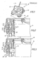
- the floor sweeper 10 shown in the drawing consists of a housing 11.
- the housing 11 serves on the outside for receiving a handle bracket 12, on which in turn a handle-like handle 13 is attached for the reciprocating movement of the floor sweeper over the floor to be cleaned.
- the housing 11 serves to receive sweeping brushes and the impellers used to move the device over a floor surface and to drive the sweeping brushes.
- a roller brush 14 is provided which extends transversely to the intended direction of movement. For the rotation of the roller brush 14 with respect to the floor to be cleaned, these are assigned to the ends of the axis 15 pinions 16, which are frictionally operatively connected to the drive wheels 17.
- the drive wheels 17 are mounted in pairs in the housing 11.
- roller brush 14 can only work up to a certain distance from the side wall regions of the floor sweeper 10, additional brushes 18 are provided for detecting the side wall regions, with the aid of which the side regions lying outside the range of action of the roller brush 14 can also be detected, as a result of which also a complete one Cleaning the floor along shoulders and walls as well as in corner areas is possible.
- each of the front corner areas of the floor sweeper 10 there is an addition Brush 18 arranged in each of the front corner areas of the floor sweeper 10 such that they are rotatable about a substantially upright axis and with their cup-shaped, ie radially outward and downward arranged bristle ring the area of action of the roller brush 14 on the one hand and the side wall and front wall area of the On the other hand, housing 11 overlap.
- the two additional brushes 18 are coupled in a drive-locking manner with drive impellers which are not shown in detail and are arranged in between.
- the bearing bracket 19 is formed by an approximately U-shaped bracket 20 made of spring steel and can be positively attached to the two legs 20, 21 of the U-shaped bracket 20 onto a downward-facing wall part 23 of the housing 11.
- the bearing clasp 19, forming an approximately U-shaped bracket 20 has an integrally formed, tubular bearing receptacle 24 on the inside of the one leg 21.
- the second leg 22 of the approximately U-shaped bracket 20 is provided with a recess 25 extending from its free end for the passage of the bearing receptacle 24.
- the leg 22 which has the cutout 25 for the passage of the bearing receptacle 24 has at its free end obliquely outwardly angled portions 26 to form an insertion bevel 27. With this insertion bevel 27, the mounting of the bearing clasp 19 on the downward wall part 23 of the housing 11 is facilitated.
- the distance between the two legs 21, 22 of the approximately U-shaped bracket 20 decreases somewhat from the apex part 28 to the free ends of the legs 21, 22. As a result, the two legs 21, 22 bear against the downwardly directed wall part 23 of the housing 11 with prestress.
- the leg 21 of the approximately U-shaped bracket 20, which has the tubular bearing receptacle 24, is somewhat longer than the second leg 22 and has at its free end an inwardly directed, right-angled bend 29 for engaging in a recess 30 that engages in the bracket 20 Housing wall 23 on. In this way, an unintentional loosening of the bearing clasp 19 is prevented.
- the inward, right-angled bend 29 of the first leg 21 of the clamp 20 lies with its side surface 31 facing the apex part 28 against a shoulder 32 of the housing wall 23.
- the offset shoulder 32 is formed by the recess 30.
- the roller brush 14 When mounting the roller brush 14, the two bearing clips 19 must be placed on the ends of the roller brush 14.
- the roller brush 14 has offset shoulders 33 on the pinions 16.
- the offset lugs 33 of the pinion 16 thus form cylindrical bearing ends which engage in the bearing receptacles 24 of the bearing clasp 19.
- the roller brush 14 is thus rotatably supported in the two bearing clips 19.
- the two bearing clips 19 are then pressed together with the roller brush 14 arranged therein onto the wall parts 23 of the housing 11. The assembly is very easy.
- the axis 15 of the roller brush 14 consists of two wires 35 twisted together, between which the bristles, not shown, are clamped. The free ends of the twisted wires 35 engage in a recess 36 of the pinion 16.
- the axis 15 is formed from wood, in which individual tufts of bristles, not shown, are inserted. The free end of the wooden axis 15 is also inserted into a recess 36 of the pinion 16.
- the bearing clasp 19 rests with the tubular bearing receptacle 24 against the end wall 37 of a recess 38 of the wall part 23 of the housing 11 which is open at the bottom. This also prevents the bearing clasp 19 from slipping laterally after being placed on the downwardly directed wall part 23 of the housing 11.
- the downward-facing wall part 23 of the housing 11 also has lateral ribs 39 which bear against the sides of the bearing bracket 19.
- the approximately U-shaped bracket 20 forming the bearing bracket 19 has an opening 40 in its apex part 28 for inserting a screwdriver or the like which serves to spread the bracket legs 21, 22 apart. This spreading of the clamp legs 21, 22 with a screwdriver or the like enables the bearing clasp 19 to be removed and the roller brush 14 to be dismantled in a simple manner.
Landscapes
- Brushes (AREA)
- Nozzles For Electric Vacuum Cleaners (AREA)
- Cleaning Of Streets, Tracks, Or Beaches (AREA)
- Cleaning In General (AREA)
Applications Claiming Priority (2)
| Application Number | Priority Date | Filing Date | Title |
|---|---|---|---|
| DE19813100372 DE3100372A1 (de) | 1981-01-09 | 1981-01-09 | "bodenkehrmaschine" |
| DE3100372 | 1981-01-09 |
Publications (2)
| Publication Number | Publication Date |
|---|---|
| EP0056252A2 true EP0056252A2 (fr) | 1982-07-21 |
| EP0056252A3 EP0056252A3 (fr) | 1982-08-18 |
Family
ID=6122327
Family Applications (2)
| Application Number | Title | Priority Date | Filing Date |
|---|---|---|---|
| EP82900245A Expired EP0069135B1 (fr) | 1981-01-09 | 1982-01-07 | Balai mecanique |
| EP82100083A Pending EP0056252A3 (fr) | 1981-01-09 | 1982-01-08 | Appareil à balayer le plancher |
Family Applications Before (1)
| Application Number | Title | Priority Date | Filing Date |
|---|---|---|---|
| EP82900245A Expired EP0069135B1 (fr) | 1981-01-09 | 1982-01-07 | Balai mecanique |
Country Status (6)
| Country | Link |
|---|---|
| US (1) | US4484372A (fr) |
| EP (2) | EP0069135B1 (fr) |
| JP (1) | JPS57502091A (fr) |
| AU (1) | AU561972B2 (fr) |
| DE (1) | DE3100372A1 (fr) |
| WO (1) | WO1982002331A1 (fr) |
Families Citing this family (6)
| Publication number | Priority date | Publication date | Assignee | Title |
|---|---|---|---|---|
| US4662027A (en) * | 1985-10-21 | 1987-05-05 | Parker Winfred C | Brush roller attachment kit |
| FR2704741B1 (fr) * | 1993-05-05 | 1995-07-21 | Blairon Michel | Dispositif de nettoyage de surface par projection de vapeur avec ou sans aspiration. |
| DE19820628C1 (de) * | 1998-05-08 | 1999-09-23 | Kaercher Gmbh & Co Alfred | Kehrmaschine |
| DE20009539U1 (de) * | 2000-05-26 | 2001-08-02 | OTEC Präzisionsfinish GmbH, 75334 Straubenhardt | Vorrichtung zum Schleifen von Schleifgut |
| US6782996B1 (en) * | 2003-02-13 | 2004-08-31 | Rapistan Systems Advertising Corp. | Axle cartridge for conveyor roller |
| DE102006003086B3 (de) | 2006-01-20 | 2007-05-31 | Leifheit Ag | Kehrmaschine |
Family Cites Families (10)
| Publication number | Priority date | Publication date | Assignee | Title |
|---|---|---|---|---|
| US1822522A (en) * | 1927-10-19 | 1931-09-08 | Benjamin D Goldberg | Vacuum cleaner |
| US2226581A (en) * | 1939-02-02 | 1940-12-31 | Richardson Irving | Carpet sweeper |
| GB638541A (en) * | 1948-03-12 | 1950-06-07 | Entwisle & Kenyon Ltd | Improvements in carpet sweepers |
| US2962740A (en) * | 1958-07-21 | 1960-12-06 | Bissell Inc | Carpet sweeper |
| DE1869502U (de) * | 1963-01-25 | 1963-03-28 | Bremshey & Co | Teppichkehrmaschine. |
| DE2049835C3 (de) * | 1969-10-13 | 1974-11-14 | Hiroshi Nagareyama Chiba Fukuba (Japan) | Teppichkehrmaschine |
| US3651529A (en) * | 1969-11-24 | 1972-03-28 | Popeil Brothers | Cleaning brush |
| JPS5331105U (fr) * | 1976-08-24 | 1978-03-17 | ||
| JPS5544607A (en) * | 1978-09-25 | 1980-03-29 | Toshiba Corp | Document producing device |
| US4357727A (en) * | 1980-12-04 | 1982-11-09 | Bissell, Inc. | Dual brush floor sweeper |
-
1981
- 1981-01-09 DE DE19813100372 patent/DE3100372A1/de active Granted
-
1982
- 1982-01-07 EP EP82900245A patent/EP0069135B1/fr not_active Expired
- 1982-01-07 US US06/422,980 patent/US4484372A/en not_active Expired - Fee Related
- 1982-01-07 JP JP57500283A patent/JPS57502091A/ja active Pending
- 1982-01-07 AU AU80019/82A patent/AU561972B2/en not_active Ceased
- 1982-01-07 WO PCT/DE1982/000005 patent/WO1982002331A1/fr not_active Ceased
- 1982-01-08 EP EP82100083A patent/EP0056252A3/fr active Pending
Also Published As
| Publication number | Publication date |
|---|---|
| EP0069135B1 (fr) | 1985-04-10 |
| WO1982002331A1 (fr) | 1982-07-22 |
| DE3100372A1 (de) | 1982-08-12 |
| AU561972B2 (en) | 1987-05-21 |
| DE3100372C2 (fr) | 1990-09-06 |
| EP0056252A3 (fr) | 1982-08-18 |
| US4484372A (en) | 1984-11-27 |
| EP0069135A1 (fr) | 1983-01-12 |
| AU8001982A (en) | 1982-08-02 |
| JPS57502091A (fr) | 1982-11-25 |
Similar Documents
| Publication | Publication Date | Title |
|---|---|---|
| DE3100497C2 (fr) | ||
| DE10358683B4 (de) | Vorrichtung zum Verbinden eines Trägerteils und eines Anbauteils | |
| EP1729377A1 (fr) | Dispositif de verrouillage pour connecteur enfichable | |
| EP0056252A2 (fr) | Appareil à balayer le plancher | |
| DE2918716C2 (de) | Bodenkehrer | |
| DE7933811U1 (de) | Vorrichtung zur Verbindung eines Zusatzteils mit dem Boden eines Schachtes oder einer Schelle aus Kunststoff mit einem U-förmigen Profil zur Halterung elektrischer Kabel | |
| EP0131172B1 (fr) | Raccord pour éléments en bois | |
| EP4019819A1 (fr) | Dispositif à deux composants, en particulier collier doté d'un anneau de collier | |
| DE2520025A1 (de) | Griffbefestigung fuer buegelgriffe an toepfen oder dergleichen | |
| DE29701179U1 (de) | Reinigungsgerät | |
| EP0669675B1 (fr) | Contact électrique | |
| DE7929989U1 (de) | Halter zum Festsetzen von lose eingesetzten Teilen in einem Gehäuse | |
| DE2518954B2 (de) | Isoliergriff fuer haushaltsgeraete | |
| DE8027607U1 (de) | Arbeitsgerät, wie Gartengerät, Feldgerät, Putzgerät o.dgl | |
| DE1154245B (de) | Halter zum Befestigen von Tragschienen fuer Gardinen, Vorhaenge u. dgl. | |
| DE2611683C3 (de) | Vorrichtung zum lösbaren Befestigen von Reinigungsgeräten an einem Stiel | |
| DE20305948U1 (de) | Kabelhaltebügel | |
| DE69205727T2 (de) | Vorrichtung für die abnehmbare Montage einer Plinthe auf dem Boden eines Möbels. | |
| DE1231331B (de) | Unterputzdose fuer elektrische Schalter od. dgl. | |
| DE3813351C2 (fr) | ||
| DE8709686U1 (de) | Halter für Blitzableiterdrähte | |
| DE9216445U1 (de) | Vorrichtung zum Halten eines Schirmes in Kraftfahrzeugen | |
| DE1588520A1 (de) | Sicherungssockel zum Befestigen an einer Tragschiene | |
| DE10215827B4 (de) | Lampenfassung | |
| EP0992739A2 (fr) | Support de lampe comprenant un connecteur femelle avec une tête de lampe enfichable |
Legal Events
| Date | Code | Title | Description |
|---|---|---|---|
| PUAI | Public reference made under article 153(3) epc to a published international application that has entered the european phase |
Free format text: ORIGINAL CODE: 0009012 |
|
| PUAL | Search report despatched |
Free format text: ORIGINAL CODE: 0009013 |
|
| AK | Designated contracting states |
Designated state(s): IT |
|
| AK | Designated contracting states |
Designated state(s): IT |
|
| STAA | Information on the status of an ep patent application or granted ep patent |
Free format text: STATUS: REQUEST FOR EXAMINATION WAS MADE |
|
| 17P | Request for examination filed |
Effective date: 19820923 |
|
| XX | Miscellaneous (additional remarks) |
Free format text: VERFAHREN ABGESCHLOSSEN INFOLGE VERBINDUNG MIT 82900245.0 (EUROPAEISCHE ANMELDENUMMER) DURCH ENTSCHEIDUNG VOM 16.09.83. |
|
| RIN1 | Information on inventor provided before grant (corrected) |
Inventor name: TIWI, PETER Inventor name: PAETZOLD, DIETER Inventor name: SCHREIBER, ALFONS |