EP0056476B1 - Verfahren zur Erhöhung des Heizwertes eines Gases - Google Patents
Verfahren zur Erhöhung des Heizwertes eines Gases Download PDFInfo
- Publication number
- EP0056476B1 EP0056476B1 EP19810110641 EP81110641A EP0056476B1 EP 0056476 B1 EP0056476 B1 EP 0056476B1 EP 19810110641 EP19810110641 EP 19810110641 EP 81110641 A EP81110641 A EP 81110641A EP 0056476 B1 EP0056476 B1 EP 0056476B1
- Authority
- EP
- European Patent Office
- Prior art keywords
- gas
- calorific value
- pressure
- propane
- higher calorific
- Prior art date
- Legal status (The legal status is an assumption and is not a legal conclusion. Google has not performed a legal analysis and makes no representation as to the accuracy of the status listed.)
- Expired
Links
Images

Classifications
-
- C—CHEMISTRY; METALLURGY
- C10—PETROLEUM, GAS OR COKE INDUSTRIES; TECHNICAL GASES CONTAINING CARBON MONOXIDE; FUELS; LUBRICANTS; PEAT
- C10K—PURIFYING OR MODIFYING THE CHEMICAL COMPOSITION OF COMBUSTIBLE GASES CONTAINING CARBON MONOXIDE
- C10K3/00—Modifying the chemical composition of combustible gases containing carbon monoxide to produce an improved fuel, e.g. one of different calorific value, which may be free from carbon monoxide
- C10K3/06—Modifying the chemical composition of combustible gases containing carbon monoxide to produce an improved fuel, e.g. one of different calorific value, which may be free from carbon monoxide by mixing with gases
-
- C—CHEMISTRY; METALLURGY
- C10—PETROLEUM, GAS OR COKE INDUSTRIES; TECHNICAL GASES CONTAINING CARBON MONOXIDE; FUELS; LUBRICANTS; PEAT
- C10L—FUELS NOT OTHERWISE PROVIDED FOR; NATURAL GAS; SYNTHETIC NATURAL GAS OBTAINED BY PROCESSES NOT COVERED BY SUBCLASSES C10G OR C10K; LIQUIFIED PETROLEUM GAS; USE OF ADDITIVES TO FUELS OR FIRES; FIRE-LIGHTERS
- C10L3/00—Gaseous fuels; Natural gas; Synthetic natural gas obtained by processes not covered by subclass C10G, C10K; Liquefied petroleum gas
Definitions
- the invention relates to a method for increasing the calorific value of a gas of low calorific value, e.g. Natural gas, coke gas, by adding a gas of higher calorific value, e.g. Propane, propane mixture, in which a gas is heated and the two gases are mixed together by means of atomization, the heating being carried out by means of a heat exchanger.
- a gas of low calorific value e.g. Natural gas, coke gas
- a gas of higher calorific value e.g. Propane, propane mixture
- a gas component with a higher calorific value is often added to the gas with a lower calorific value, natural gas generally being the addition of propane.
- propane is to be understood as pure propane, propane with a mixture of ethanes, propane with a mixture of butanes or propane mixed with ethane and butane.
- the natural gas or the like is heated in a side stream and the gas component of higher calorific value, in particular propane, is injected into this heated gas stream. After a mixing section, the side stream is reintroduced into the main line.
- propane the gas component of higher calorific value
- the side stream is reintroduced into the main line.
- Another conventional method overcomes the disadvantage of the method described above by evaporating the propane to be added to the natural gas.
- the pressure of the propane vapor will only be slightly above the gas pressure in the natural gas pipeline, which in regional distribution systems will be in the range of 20 to 35 bar.
- the entrainment of liquid propane into the gas flow must be prevented via a large steam chamber or a downstream separator, since the liquid phase in the steam line leads to liquid hammer and irregularities in the downstream volume control.
- there is a complex regulation for the liquid level in the evaporator and the quantity regulation of the admixture In addition to the high expenditure on equipment, there is a complex regulation for the liquid level in the evaporator and the quantity regulation of the admixture. This evaporation system also leads to difficulties in the liquid level control in the evaporator with increasing pressures near the critical pressure of propane.
- the object of the invention is to carry out the enrichment of the gas of low calorific value, in particular natural gas, by admixing a gas component of higher calorific value, primarily propane or the like, in a safer and more effective manner.
- the invention is characterized in that the gas of higher calorific value, e.g.
- Propane or the like brought to a pressure above its two-phase range (wet steam area), then heated and then mixed with the gas of low calorific value, the heating of the gas of higher calorific value being carried out to such an extent that, when this gas expands, to the pressure of the Gas of low calorific value and further up to the partial pressure of the gas of higher calorific value, the relaxation in the gas mixture takes place outside the wet steam area of the gas of higher calorific value.
- the gas of low calorific value flowing through the high output remains untreated and the amount of heat necessary for a complete gas mixture is obtained with the temperature of the gas of low calorific value in the pipeline essentially unchanged by heating the mixture to be mixed Gases supplied.
- the gas with a higher calorific value ie propane or the like
- propane or the like is fed directly into the natural gas line without the gas temperature having to be raised.
- the heated gas of higher calorific value can be injected immediately at a corresponding pressure. If the pressure of the gas of low calorific value is below the critical pressure of the gas of higher calorific value explained above, the higher pressure in the heater for the gas of higher calorific value is advantageously ensured via a pressure control, immediately after heating the gas of higher calorific value Calorific value. Any excess amount of the gas component with a higher calorific value can be returned to its storage room. This is conveniently done immediately after the pump, i.e. the cold area of the gas of higher calorific value, e.g. of the propane. This allows the overflow line to be returned to the storage tank.
- the pump i.e. the cold area of the gas of higher calorific value, e.g. of the propane.
- the heating of the gas with a higher calorific value can expediently be carried out by means of a heat transfer circuit. It can be done by means of the heat exchanger by high pressure steam, the boiler for generating the high pressure steam using the gas of the low calorific value, e.g. Natural gas, or the gas of higher calorific value, e.g. Propane to be heated.
- the gas of the low calorific value e.g. Natural gas
- the gas of higher calorific value e.g. Propane to be heated.
- the temperature in line 1 does not differentiate 278 K.
- propane should be added, avoiding the elimination of liquid propane and heavier gas components in the transport line.
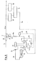
- Propane is brought from the storage facility 2 to the pressure required for injection at 3 into the natural gas line 1, e.g. by means of a multi-stage centrifugal pump 4.
- Excess propane is conveyed back to the storage facility 2 via a control valve 5 and the line 6.
- a quantity control takes place via a corresponding control device 7 for regulating the addition of propane.
- the values of a device 8 relating to temperature, pressure and gas analysis, a device 9 relating to dew point determination and a device 10 relating to quantity measurement are introduced into device 7.
- a control line 11 leads to the control valve 5 via a quantity measuring device 12 to the control valve 5.
- the propane determined by the quantity control in a heat exchanger 14 is heated to approximately 400 K and is conducted via an insulated line 15 to the injection element 3 on the natural gas line 1. Mixing with the natural gas takes place there with cooling of the propane.
- the boiler 18 can be used, for example, to produce high-pressure steam by burning propane, natural gas or another fuel.
- the output of the boiler 18 is regulated by means of a further control line 19 and a temperature measuring device 20.
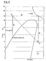
- FIG. 2 shows the method of FIG. 1 in an i-logp state diagram.
- Line 1 describes the pressure increase in the liquid area from the storage pressure to approx. 60 bar (the pump pressure will be above the natural gas pressure due to the device-related pressure losses).
- Line 2 illustrates the temperature increase and volume change due to the supply of heat.
- a propane addition of 8 mol% may be possible without the formation of hydrocarbon condensate. This will correspond to a partial pressure of the propane in the gas mixture of 4.8 bar.
- the relaxation The propane takes place without work, heat supply or removal from the total mixture, ie adiabatic (enthalpy constant), and is represented by line 3. The relaxation takes place in the gas area. A two-phase formation with the possibility of separating liquid is avoided.
- This representation of the propane expansion to the partial pressure in the natural gas mixture is a simplification, which is only intended to illustrate how the energy required for the mixture is taken from the heated propane.
- the dashed line indicates how the state of the propane changes in the conventional process, whereby a liquid propane phase with the possible risk of separation on the pipe wall is present until it is completely mixed with the natural gas, from which energy is simultaneously extracted.
- propane is intended to increase the calorific value, although an addition of 15 mol% of dew point problems cannot be expected.
- Propane is extracted from propane storage 2a (Fig. 3) by means of a positive displacement pump 4a, e.g. a diaphragm metering pump for volume control, brought to a pressure of approx. 50 bar.
- a pressure regulator 22 keeps this pressure constant since the gas pressure in the coke gas line 1 a is significantly lower.
- the pump 4a feeds into a buffer or storage container 23. This serves as a pulsation damper or storage of cold propane. If the pressure regulator 22 were to shut off the propane feed line 15a, the propane expanding in the heater 14 could relax in the storage tank 23. However, only cold propane is pressed into the storage container 2a via the pressure relief valve 24 of the storage container 23. This prevents warm propane from relaxing directly into the atmosphere.
- the heat exchanger 14 and the heat transfer circuit 16, 17, 18 can be designed as in Example 1, FIG. 1.
- the device 7a for regulating the addition of propane is supplied with measured values from the device 25 relating to calorific value determination and the device 26 relating to quantity measurement, volume, temperature and pressure.
- a control line 11 leads to the propane metering pump 4a.
- the propane quantity control corresponds to the gas requirement and the calorific value is set directly on the metering pump by changing the flow rate.
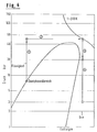
- Example 2 The procedures of Example 2 are shown in the propane state diagram of FIG. 4.
- Line 1 represents the pressure increase of the propane
- line 2 the heating to approx. 390 K.
- the pressure regulator 22 and the injection point 3 the throttling to the line pressure of 20 bar takes place (line 3).
- line 4 The further expansion of propane to the partial pressure of approx. 3 bar in the gas mixture is shown by line 4 and should only be seen as an approximation.
- the injection device 3 advantageously consists of a container or a tube extension 28 and one or more injection nozzles 29, the arrangement of the nozzles guaranteeing thorough mixing, e.g. when injected in the counterflow direction to the coke gas flow.
- a spring-loaded design can be selected. If there are several nozzles, these can be equipped with spring loads of different sizes in order to ensure that the nozzles start working one after the other with increasing pre-pressure.
Landscapes
- Chemical & Material Sciences (AREA)
- Engineering & Computer Science (AREA)
- Oil, Petroleum & Natural Gas (AREA)
- Chemical Kinetics & Catalysis (AREA)
- General Chemical & Material Sciences (AREA)
- Organic Chemistry (AREA)
- Combustion & Propulsion (AREA)
- Filling Or Discharging Of Gas Storage Vessels (AREA)
Description
- Die Erfindung bezieht sich auf ein Verfahren zur Erhöhung des Heizwertes eines Gases von niedrigem Heizwert, z.B. Erdgas, Koksgas, durch Zusetzen eines Gases von höherem Heizwert, z.B. Propan, Propan-Mischung, bei dem ein Gas erwärmt und die beiden Gase mittels Verdüsung miteinander vermischt werden, wobei die Erwärmung mittels eines Wärmetauschers durchgeführt wird.
- Zur Aufwertung eines Gases von niedrigem Heizwert, z.B. Erdgas, in ein Gas mit höherem Heizwert wird dem Gas mit niedrigerem Heizwert häufig eine Gaskomponente von höherem Heizwert zugesetzt, wobei es sich bei Erdgas im allgemeinen um das Zusetzen von Propan handelt. Unter Propan ist reines Propan, Propan mit Äthan-Gemisch, Propan mit Butan-Gemisch oder Propan mit Äthan und Butan gemischt zu verstehen.
- In der herkömmlichen Methode der Erhöhung des Heizwertes wird das Erdgas oder dergleichen in einem Seitenstrom erwärmt und es wird die Gaskomponente höheren Heizwertes, vor allem Propan, in diesen erwärmten Gasstrom eingedüst. Nach einer Mischstrecke wird der Seitenstrom wieder in die Hauptleitung eingeführt. Bei dieser Methode kann nicht ausgeschlossen werden, dass sich bis zur vollständigen Durchmischung des Propans mit dem Erdgas, welchem gleichzeitig Energie entzogen wird, eine flüssige Propanphase mit der möglichen Gefahr der Abscheidung an der Rohrwandung ergibt. Es wird dem angewärmten Erdgas durch Verdampfung von eingespritztem kaltem Propan oder dergleichen Wärme entzogen. Eine vollständige Verdampfung ohne Ausscheidung von flüssigem Propan oder dergleichen setzt eine sehr feine Einspritzung und eine gleichmässige Verteilung des Propans voraus, was in der Praxis schwierig einzuhalten ist.
- Eine weitere herkömmliche Methode überwindet den Nachteil des vorstehend beschriebenen Verfahrens, indem das dem Erdgas zuzumischende Propan verdampft wird. Der Druck des Propandampfes wird nur unwesentlich über dem Gasdruck in der Erdgasleitung liegen, welcher bei regionalen Verteilungssystemen im Bereich von 20 bis 35 bar liegen wird. Im Propanverdampfer liegen bei diesen Drücken zwei Phasen vor, flüssiges und gasförmiges Propan. Ein Mitreissen von flüssigem Propan in den Gasstrom muss über einen grossen Dampfraum oder über einen nachgeschalteten Abscheider verhindert werden, da die flüssige Phase in der Dampfleitung zu Flüssigkeitsschlägen und Unregelmässigkeiten in der nachgeschalteten Mengenregelung führt. Zu dem hohen apparativen Aufwand kommt eine komplexe Regelung für das Flüssigkeitsniveau im Verdampfer und die Mengenregelung der Zumischung. Dieses System der Verdampfung führt zudem bei steigenden Drücken in der Nähe des kritischen Druckes von Propan zu Schwierigkeiten in der Flüssigkeitsniveau- Regelung im Verdampfer.
- Aufgabe der Erfindung ist es, das Anreichern des Gases von niedrigem Heizwert, insbesondere von Erdgas, durch Zumischen einer Gaskomponente von höherem Heizwert, vornehmlich Propan oder dergleichen, sicherer und wirksamer durchzuführen. Bei dem Verfahren der anfangs genannten Art zeichnet sich die Erfindung dadurch aus, dass das Gas von höherem Heizwert, z.B. Propan oder dergleichen, auf einen Druck oberhalb seines Zweiphasenbereiches (Nassdampfgebiet) gebracht, danach erwärmt und dann dem Gas von niedrigem Heizwert zugemischt wird, wobei die Erwärmung des Gases von höherem Heizwert so weit durchgeführt wird, dass bei der Entspannung dieses Gases auf den Druck des Gases von niedrigem Heizwert und weiter bis zum Partialdruck des Gases von höherem Heizwert die Entspannung in dem Gasgemisch ausserhalb des Nassdampfgebietes des Gases von höherem Heizwert erfolgt.
- Bei einem solchen Verfahren bleibt das durch die hohe Leistung, z.B. die Versorgungsleitung oder dergleichen, strömende Gas von niedrigem Heizwert unbehandelt und es wird die zu einer vollkommenen Gasmischung notwendige Wärmemenge bei im wesentlichen unveränderter Temperatur des Gases von niedrigem Heizwert in der Rohrleitung durch Anwärmen des zuzumischenden Gases zugeführt. Die Einspeisung des Gases von höherem Heizwert, d.h. von Propan oder dergleichen, erfolgt unmittelbar in die Erdgasleitung, ohne dass die Gastemperatur angehoben werden muss. Bei Entspannen des erwärmten Propans oder dergleichen auf den Gasdruck in der Rohrleitung und weiter auf den Partialdruck in dem Gasgemisch wird bei ausreichender Anwärmung des Gases höheren Heizwertes, insbesondere von Propan, eine Zweiphasenbildung mit entsprechendem Nachteil bei der Mischung des Propans mit dem Leitungsgas verhindert. Verglichen mit dem üblichen System von angewärmtem Gas von niedrigerem Heizwert und kaltem zuzuführenden Gas von höherem Heizwert ist bei dem unbehandelten Gas von niedrigerem Heizwert, d.h. von Erdgas, und warmem Propan oder dergleichen, ein geringerer Unterschied der Dichte gegeben. Die Durchmischung der Komponenten erfolgt rascher, wobei die Gefahr einer Ausscheidung von flüssigem Propan oder dergleichen an dem Rohrrand praktisch ausgeschaltet ist. Die zur Gemischbildung zuzuführende Wärmemenge ist bereits in dem eingespritzten Gas von höherem Heizwert, z.B. des Propans oder dergleichen, enthalten. Während der Gemischbildung wird die Konzentration von 100% Propan oder dergleichen auf die gewünschte Konzentration absinken. Dabei gehen Verdünnung und Temperaturabsenkung parallel, so dass es nicht zu einer Flüssigkeitsabscheidung kommen kann. Weiterhin ergibt sich ein Wärmetauscher geringerer Abmessung verglichen mit einer Anwärmevorrichtung für Gas von niedrigem Heizwert gleicher Wärmeleistung, da bessere Wärmeübergangsverhältnisse geschaffen sind. Der bauliche Aufwand für den Wärmetauscher wird geringer. Dabei können auch die Wärmeverluste, z.B. durch Abstrahlung oder dergleichen, niedriger gehalten werden. Man kann weiterhin die Erdgasleitung oder dergleichen unterirdisch verlaufen lassen. Eine By-Pass-Leitung ist nicht erforderlich. Das Verfahren der Erfindung ist im Prinzip vom Druck in der Erdgasleitung unabhängig.
- Wenn das Gas von niedrigem Heizwert in der Transportleitung einen Druck aufweist, der über dem kritischen Punkt in bezug auf das Nassdampfgebiet des zuzumischenden Gases von höherem Heizwert liegt, kann das erwärmte Gas von höherem Heizwert bei einem entsprechenden Druck unmittelbar zugedüst werden. Wenn der Druck des Gases von niedrigem Heizwert unterhalb des vorstehend erläuterten kritischen Drukkes des Gases von höherem Heizwert liegt, wird der höhere Druck in dem Anwärmer für das Gas von höherem Heizwert vorteilhaft über eine Druckregelung sichergestellt, und zwar unmittelbar nach der Erwärmung des Gases von höherem Heizwert. Eventuell zuviel geförderte Menge von der Gaskomponente von höherem Heizwert kann zu seinem Vorratsraum wieder zurückgeführt werden. Dies geschieht zweckmässig unmittelbar nach der Pumpe, d.h. dem kalten Bereich des Gases von höherem Heizwert, z.B. des Propans. Dadurch lässt sich die Überströmleitung in den Lagertank zurückführen.
- Für den letzteren Fall ist es weiterhin vorteilhaft, wenn die auf Druck gebrachte Gaskomponente von höherem Heizwert vor der Erwärmung über einen Speicherraum geführt wird. Dies hat den Vorteil, dass, selbst wenn die Leitung bei Betrieb des Wärmetauschers beidseitig abgesperrt wird, das warme, sich ausdehnende Gas von höherem Heizwert, z.B. Propan oder dergleichen, zurück in den Speicherraum drücken kann. Im Falle des Ansprechens eines Drucksicherheitsventils wird lediglich kaltes Propan oder dergleichen zurück in den Sammelbehälter gefördert werden.
- Die Erwärmung des Gases von höherem Heizwert kann zweckmässig mittels eines Wärmeträgerkreislaufes vorgenommen werdne. Sie kann mittels des Wärmetauschers durch Hochdruckdampf erfolgen, wobei der Kessel zur Erzeugung des Hochdruckdampfes mittels des Gases des niedrigen Heizwertes, z.B. Erdgas, oder des Gases des höheren Heizwertes, z.B. Propan, geheizt werden.
- Die Erfindung wird anhand der in der Zeichnung dargestellten Verfahrensbeispiele und der zugehörigen Zustandsdiagramme nachstehend erläutert, wobei es sich im ersten Beispiel um die Vermischung von Erdgas und Propan und in dem zweiten Beispiel um die Herstellung eines Gemisches von Koksgas und Propan handelt.
- Fig. 1 zeigt das Verfahrensschema des ersten Beispiels, während
- Fig. 2 das Verfahren im Zustandsdiagramm für Propan veranschaulicht.
- Fig. 3 stellt das Verfahrensschema des zweiten Beispiels dar, und
- Fig. 4 erläutert das Verfahren im zugehörigen Zustandsdiagramm für Propan.
- Bei dem Beispiel 1 der Fig. 1 und 2 fliesst durch eine Ferngasleitung 1 mit einem Betriebsdruck von 60 bar Erdgas mit folgender Zusammensetzung:

- Die Temperatur in der Leitung 1 unterscheidet 278 K nicht. Zur Heizwerterhöhung des Erdgases soll Propan zugesetzt werden, wobei ein Ausscheiden von flüssigem Propan und schwereren Gasbestandteilen in der Transportleitung zu vermeiden ist.
- Aus dem Vorratslager 2 wird Propan auf den zur Eindüsung bei 3 in die Erdgasleitung 1 erforderlichen Druck gebracht, z.B. durch eine mehrstufige Kreiselpumpe 4. Überflüssiges Propan wird über ein Regelventil 5 und die Leitung 6 zurück zum Vorratslager 2 gefördert. Es erfolgt eine Mengenregelung über eine entsprechende Steuerungsvorrichtung 7 für die Regelung der Propan-Zugabe. In die Vorrichtung 7 werden die Werte einer Vorrichtung 8 betreffend Temperatur, Druck und Gasanalyse, einer Vorrichtung 9 betreffend Taupunktbestimmung und einer Vorrichtung 10 betreffend Mengenmessung eingebracht. Eine Steuerleitung 11 führt zu dem Regelventil 5 über eine Mengenmessvorrichtung 12 zu dem Regelventil 5.
- Das von der Mengenregelung bestimmte Propan in einem Wärmetauscher 14 wird auf ca. 400 K angewärmt und über eine isolierte Leitung 15 zum Eindüsungsorgan 3 an der Erdgasleitung 1 geführt. Dort erfolgt die Durchmischung mit dem Erdgas unter Abkühlung des Propans.
- Zur Erwärmung des Propans mittels des Wärmetauschers 14 dient ein Wärmeträgerkreislauf 16, in dem eine Pumpe 17 und ein Kessel 18 angeordnet sind. Mit dem Kessel 18 kann beispielsweise Hochdruckdampf durch Verbrennung von Propan, Erdgas oder einem anderen Brennmittel erzeugt werden. Mittels einer weiteren Steuerleitung 19 und einer Temperaturmessvorrichtung 20 wird die Leistung des Kessels 18 reguliert.
- In der Fig. 2 ist das Verfahren der Fig. 1 in einem i-logp-Zustandsdiagramm dargestellt. Linie 1 beschreibt die Druckerhöhung im Flüssigkeitsbereich vom Lagerdruck auf ca. 60 bar (Der Pumpendruck wird um die apparate-bedingten Druckverluste oberhalb des Erdgasdruckes liegen).
- Linie 2 veranschaulicht die Temperaturerhöhung und Volumenänderung durch Wärmezufuhr.
- Bei einer Erdgastemperatur von +5°C mit obiger Zusammensetzung und Druck kann eine Propan-Zugabe von 8 Mol.% ohne Bildung von Kohlenwasserstoffkondensat möglich sein. Dies wird einem Partialdruck des Propans in der Gasmischung von 4.8 bar entsprechen. Die Entspannung des Propans erfolgt ohne Arbeitsleistung, Wärmezufuhr oder Abfuhr aus dem Gesamtgemisch, d.h. adiabatisch (Enthalpie konstant), und ist durch die Linie 3 dargestellt. Die Entspannung erfolgt im Gasbereich. Eine Zweiphasenbildung mit der Möglichkeit der Abscheidung von Flüssigkeit ist vermieden.
- Diese Darstellung der Propan-Entspannung auf den Partialdruck im Erdgasgemisch ist eine Vereinfachung, welche lediglich veranschaulichen soll, wie die zur Mischung notwendige Energie aus dem erwärmten Propan genommen wird. Die gestrichelte Linie deutet an, wie die Zustandsänderung des Propans beim konventionellen Verfahren verläuft, wobei bis zur vollständigen Durchmischung mit dem Erdgas, welchem gleichzeitig Energie entzogen wird, eine flüssige Propanphase mit der möglichen Gefahr der Abscheidung an der Rohrwandung vorhanden ist.
- Eine Nachrechnung mittels EDV als Vielkomponentensystem der Gemischbildung aus Propan bei 60 bar und 400 K sowie dem Erdgas bei 60 bar und 278 K ergab eine Gemischtemperatur oberhalb 280 K, d.h. die Anwärmung war ausreichend. Der Taupunkt des Gemisches wurde zu weniger als 260 K bestimmt, d.h. ein Ausscheiden von flüssigen Kohlewasserstoffen bei einer Betriebstemperatur von 278 K ist vermieden.
- Bei dem zweiten Beispiel der Fig. 3 und 4 strömt durch eine Verteilerleitung 1 a Koksgas bei 20 bar und Temperaturen oberhalb 265 K. Die Zusammensetzung des Gases ist wie folgt (Ruhrgas):

- Die Zugabe von Propan soll der Heizwerterhöhung dienen, wobei eine Zugabe von 15 Mol.% Taupunktprobleme nicht erwarten lässt.
- Aus dem Propanlager 2a (Fig. 3) wird Propan mittels einer Verdrängerpumpe 4a, z.B. eine zur Mengenregelung dienende Membrandosierpumpe, auf einen Druck von ca. 50 bar gebracht. Ein Druckregler 22 hält diesen Druck konstant, da der Gasdruck in der Koksgasleitung 1 a wesentlich niedriger liegt.
- Die Pumpe 4a fördert in einen Puffer- oder Speicherbehälter 23. Dieser dient als Pulsationsdämpfer oder Speicher von kaltem Propan. Wenn der Druckregler 22 die Propan-Einspeiseleitung 15a absperren sollte, könnte sich das in dem Anwärmer 14 ausdehnende Propan in den Speicherbehälter 23 entspannen. Über das Überdruckventil 24 des Speicherbehälters 23 wird jedoch nur kaltes Propan in den Lagerbehälter 2a gedrückt. Auf diese Weise vermeidet man ein Entspannen von warmem Propan direkt in die Atmosphäre.
- Der Wärmetauscher 14 und der Wärmeträgerkreislauf 16,17,18 können wie im Beispiel 1, Fig. 1, ausgeführt werden.
- Der Vorrichtung 7a zur Regelung der Propan-Zugabe werden Messwerte der Vorrichtung 25 betreffend Heizwertbestimmung und der Vorrichtung 26 betreffend Mengenmessung, Volumen, Temperatur und Druck zugeleitet. Eine Steuerleitung 11 führt zu der Propan-Dosierpumpe 4a. Die Propan-Mengenregelung entspricht dem Gasbedarf und die Heizwerteinstellung erfolgt unmittelbar an der Dosierpumpe durch Änderung der Fördermenge.
- Die Verfahrensweisen des Beispiels 2 sind in dem Propan-Zustandsdiagramm der Fig. 4 dargestellt. Linie 1 stellt die Druckerhöhung des Propans, Linie 2 die Erwärmung auf ca. 390 K dar. In dem Druckregler 22 und dem Einspritzpunkt 3 erfolgt die Drosselung auf den Leitungsdruck von 20 bar (Linie 3). Die weitere Entspannung von Propan auf den Partialdruck von ca. 3 bar im Gasgemisch ist durch die Linie 4 dargestellt und nur als Annäherung zu werten.
- Die Einspritzvorrichtung 3 besteht vorteilhaft aus einem Behälter oder einer Rohrerweiterung 28 und einer oder mehreren Einspritzdüsen 29, wobei die Anordnung der Düsen eine gute Durchmischung garantiert, z.B. bei Eindüsung in Gegenstromrichtung zum Koksgasdurchfluss. Für die Düse könnte z.B. eine federbelastete Bauart gewählt werden. Bei Vorhandensein von mehreren Düsen können diese mit unterschiedlich grossen Federbelastungen ausgerüstet sein, um zu erreichen, dass mit steigendem Vordruck die Düsen nacheinander in Tätigkeit treten.
Claims (9)
Applications Claiming Priority (2)
| Application Number | Priority Date | Filing Date | Title |
|---|---|---|---|
| DE3101063 | 1981-01-15 | ||
| DE19813101063 DE3101063C2 (de) | 1981-01-15 | 1981-01-15 | Verfahren zur Erhöhung des Heizwertes eines Gases |
Publications (2)
| Publication Number | Publication Date |
|---|---|
| EP0056476A1 EP0056476A1 (de) | 1982-07-28 |
| EP0056476B1 true EP0056476B1 (de) | 1984-07-11 |
Family
ID=6122661
Family Applications (1)
| Application Number | Title | Priority Date | Filing Date |
|---|---|---|---|
| EP19810110641 Expired EP0056476B1 (de) | 1981-01-15 | 1981-12-21 | Verfahren zur Erhöhung des Heizwertes eines Gases |
Country Status (2)
| Country | Link |
|---|---|
| EP (1) | EP0056476B1 (de) |
| DE (1) | DE3101063C2 (de) |
Families Citing this family (1)
| Publication number | Priority date | Publication date | Assignee | Title |
|---|---|---|---|---|
| CN100419050C (zh) * | 2005-07-14 | 2008-09-17 | 上海联翔置业有限公司 | 一种混空轻烃燃气掺混煤制气的制作城市混合燃气的方法 |
Family Cites Families (4)
| Publication number | Priority date | Publication date | Assignee | Title |
|---|---|---|---|---|
| FR778039A (fr) * | 1933-07-24 | 1935-03-07 | Perfectionnements aux mélanges combustibles gazeux | |
| FR1052823A (fr) * | 1951-03-16 | 1954-01-28 | Aerogen Company Ltd | Perfectionnements apportés à la fabrication des gaz |
| FR1345594A (fr) * | 1962-08-16 | 1963-12-13 | Industriebedarf Ges M B H | Procédé de carburation de gaz |
| FR2296811A1 (fr) * | 1974-12-31 | 1976-07-30 | Exxon | Procede et appareil pour produire un gaz combustible constitue par des hydrocarbures legers dilues avec un gaz porteur |
-
1981
- 1981-01-15 DE DE19813101063 patent/DE3101063C2/de not_active Expired
- 1981-12-21 EP EP19810110641 patent/EP0056476B1/de not_active Expired
Also Published As
| Publication number | Publication date |
|---|---|
| DE3101063C2 (de) | 1985-10-31 |
| EP0056476A1 (de) | 1982-07-28 |
| DE3101063A1 (de) | 1982-07-22 |
Similar Documents
| Publication | Publication Date | Title |
|---|---|---|
| DE3875006T2 (de) | Waermepumpensystem. | |
| DE69513748T2 (de) | Verfahren und Vorrichtung zum Speisen von flüssigem Rohmaterialgas | |
| DE60225152T2 (de) | Verfahren und installation zur fraktionierung eines durch pyrolyse von kohlenwasserstoffen gewonnen gases | |
| DE1551617A1 (de) | Naturgas-Verfluessigung mit gesteuertem BTU-Gehalt | |
| WO2009010250A2 (de) | Verfahren zum regeln und kühlen einer destillationskolonne | |
| DE1444484C3 (de) | Absorptionsverfahren zum Auswaschen von Schwefelwasserstoff und/oder Kohlendioxid aus Wasserstoff und/oder leichten Kohlenwasserstoffen | |
| DE1256666B (de) | Verfahren zur Verfluessigung von Gasen | |
| DE2659796A1 (de) | Verfahren zur erzeugung von waerme unter benutzung einer waermepumpe, die mit einer fluidmischung arbeitet | |
| DE2005634A1 (de) | ||
| DE2155366C2 (de) | Verfahren zum Trennen einer vorwiegend Stickstoff und Methan enthaltenden hochgespannten Erdgas-Beschickungsmischung | |
| EP0056476B1 (de) | Verfahren zur Erhöhung des Heizwertes eines Gases | |
| DE1245396C2 (de) | Verfahren zur Zwischenlagerung von Erdgas | |
| DE2103858A1 (de) | Regelvorrichtung fur eine frak tiomerte Destillationskolonne | |
| DE69418491T2 (de) | Methode zur entleerung eines tankes und eine einrichtung zur anwendung in einer solchen entleerung | |
| DE2406317A1 (de) | Verfahren zur gewinnung von stickstoff aus luft | |
| DE19958464A1 (de) | Verfahren zur Extraktivdestillation und Kolonne zur Durchführung des Verfahrens | |
| DE3037184A1 (de) | Verfahren zur synthese von harnstoff | |
| EP0017774B1 (de) | Verfahren zur Regelung der einer Extraktivdestillationskolonne am Sumpf zugeführten Wärmemenge | |
| DE628195C (de) | Verfahren zur Entnahme von unter Druck stehenden fluessigen Gasen oder Gasgemischen | |
| DE1769805A1 (de) | Verfahren zur Rektifikation von Zweistoffgemischen | |
| DE874439C (de) | Verfahren zur Druckhydrierung von Kohlen, Teeren und Mineraloelen unter Verwendung mehrerer hintereinandergeschalteter Waemeaustauscher | |
| DE903448C (de) | Verfahren zur Rektifikation von Gemischen schwankender Zusammensetzung | |
| DE2444112B2 (de) | Verfahren zur Abtrennung von C2111111 höheren Kohlenwasserstoffen und Erzeugung eines methanangereicherten Gases mit hohem Druck durch Druckrektifikation verflüssigten Erdgases | |
| DE88824C (de) | ||
| DE1252711B (de) | Verfahren zum Rektifizieren von Olefin aus olefinreichen Gasgemischen unter Ausnutzung der durch verflüssigtes Methan gas gelieferten Kalte |
Legal Events
| Date | Code | Title | Description |
|---|---|---|---|
| PUAI | Public reference made under article 153(3) epc to a published international application that has entered the european phase |
Free format text: ORIGINAL CODE: 0009012 |
|
| AK | Designated contracting states |
Designated state(s): BE FR IT NL |
|
| 17P | Request for examination filed |
Effective date: 19820807 |
|
| ITF | It: translation for a ep patent filed | ||
| GRAA | (expected) grant |
Free format text: ORIGINAL CODE: 0009210 |
|
| AK | Designated contracting states |
Designated state(s): BE FR IT NL |
|
| ET | Fr: translation filed | ||
| PGFP | Annual fee paid to national office [announced via postgrant information from national office to epo] |
Ref country code: FR Payment date: 19840924 Year of fee payment: 4 |
|
| PLBI | Opposition filed |
Free format text: ORIGINAL CODE: 0009260 |
|
| 26 | Opposition filed |
Opponent name: LINDE AKTIENGESELLSCHAFT, WIESBADEN Effective date: 19850409 |
|
| NLR1 | Nl: opposition has been filed with the epo |
Opponent name: LINDE AKTIENGESELLSCHAFT |
|
| PGFP | Annual fee paid to national office [announced via postgrant information from national office to epo] |
Ref country code: NL Payment date: 19861231 Year of fee payment: 6 |
|
| RDAG | Patent revoked |
Free format text: ORIGINAL CODE: 0009271 |
|
| STAA | Information on the status of an ep patent application or granted ep patent |
Free format text: STATUS: PATENT REVOKED |
|
| 27W | Patent revoked |
Effective date: 19880310 |
|
| NLV4 | Nl: lapsed or anulled due to non-payment of the annual fee | ||
| BERE | Be: lapsed |
Owner name: LGA GASTECHNIK G.M.B.H. Effective date: 19881231 |