EP0056487A2 - Process for the hydrogenation of coal - Google Patents
Process for the hydrogenation of coal Download PDFInfo
- Publication number
- EP0056487A2 EP0056487A2 EP81110725A EP81110725A EP0056487A2 EP 0056487 A2 EP0056487 A2 EP 0056487A2 EP 81110725 A EP81110725 A EP 81110725A EP 81110725 A EP81110725 A EP 81110725A EP 0056487 A2 EP0056487 A2 EP 0056487A2
- Authority
- EP
- European Patent Office
- Prior art keywords
- heat
- coal
- hydrogenation
- gas
- gases
- Prior art date
- Legal status (The legal status is an assumption and is not a legal conclusion. Google has not performed a legal analysis and makes no representation as to the accuracy of the status listed.)
- Granted
Links
Images
Classifications
-
- C—CHEMISTRY; METALLURGY
- C10—PETROLEUM, GAS OR COKE INDUSTRIES; TECHNICAL GASES CONTAINING CARBON MONOXIDE; FUELS; LUBRICANTS; PEAT
- C10G—CRACKING HYDROCARBON OILS; PRODUCTION OF LIQUID HYDROCARBON MIXTURES, e.g. BY DESTRUCTIVE HYDROGENATION, OLIGOMERISATION, POLYMERISATION; RECOVERY OF HYDROCARBON OILS FROM OIL-SHALE, OIL-SAND, OR GASES; REFINING MIXTURES MAINLY CONSISTING OF HYDROCARBONS; REFORMING OF NAPHTHA; MINERAL WAXES
- C10G1/00—Production of liquid hydrocarbon mixtures from oil-shale, oil-sand, or non-melting solid carbonaceous or similar materials, e.g. wood, coal
- C10G1/08—Production of liquid hydrocarbon mixtures from oil-shale, oil-sand, or non-melting solid carbonaceous or similar materials, e.g. wood, coal with moving catalysts
- C10G1/083—Production of liquid hydrocarbon mixtures from oil-shale, oil-sand, or non-melting solid carbonaceous or similar materials, e.g. wood, coal with moving catalysts in the presence of a solvent
Definitions
- the direct heat exchange between Christsdäm p fen and coal slurry would provide benefits.
- the mixing section required for direct heat exchange is less sensitive to distribution problems of the two-phase mixture, and there is no risk of cracking on overheated heat exchanger surfaces.
- the use of hydrogen as an essential component of the heat transfer gas also guarantees that the coal pulp is always heated in the presence of hydrogen.
- Direct heat exchange has also already been carried out in one step or over a limited temperature range in a countercurrent apparatus. In both cases, some of the vaporous reaction products condense out in the pulp; this limits the application of the principle of direct heat exchange to a relatively high temperature level. Extensive heat recovery through direct exchange is not possible in this way.
- the gases and vapors flowing from the reaction were cooled to a temperature not below 350 ° C., preferably to a temperature between 380 and 440 ° C., in particular 390 to 410 ° C., in a first mixing stage. Then high-boiling oils are separated in an intermediate separator. In order to achieve this temperature in the intermediate separator, a preheating section at lower temperatures is required, in which the coal slurry is preheated. With direct heat exchange, the reaction gas is cooled to temperatures lower than 350 ° C. When cooling below 350 ° C, however, an excessive amount of the reaction products would fail here and be fed back to the reactor with the coal pulp.
- reaction products in the paste and in the reaction zone is prevented by the reaction products being previously removed from the reaction gases in a cold separator at about room temperature.
- the remaining gas, freed from the oil vapor, is then heated in countercurrent with the product-laden gas flowing to the cold separator in a heat exchanger, the gas flowing to the cold separator being cooled.
- This heated gas, freed from the product can now serve as a heat carrier and supply the necessary heat to the paste in a direct heat exchange. If additional heat is required to cover a peak demand, the product-free gas can be heated with this external heat without the heat-transferring surfaces cracking or otherwise occupy themselves with carbon. '
- the advantage of the procedure according to the invention consists essentially in the fact that only clean gases enter the heat exchanger for the external heat supply, while the coal pulp is heated by direct heating in multiphase mixing sections which are considerably simpler in terms of equipment and thus cheaper, without the risk of cracking Individual pipes are laid and there is overheating on the heat exchanger surfaces.
- the coal pulp is always heated in the presence of hydrogen.
- the effect of the countercurrent principle can largely be achieved by suitable selection of the number of stages of direct heating.
- the mixing stages which are operated at temperatures below 400 ° C. and to which the heat is supplied by gas from which the product has already condensed, can also be designed as countercurrent apparatuses in order to achieve even better heat utilization.
- the advantage of the process according to the invention is that the coal pulp, which is difficult to treat, is directly mixed with gases from the process onto the reactor is brought to the temperature, the external heat supply, in contrast to a single-stage circuit, can usually be omitted entirely or at least kept significantly smaller.
- the multi-stage direct mixing is made possible by separating the gas from the product of value after the first mixing section, so that no product can fail in the colder mixing stages. It is only through the multi-stage direct mixing that the known advantages of direct heating over indirect heating in tubular bilge heat exchangers can be optimally used: With direct heating in a mixing section, the problem of distributing the coal slurry in the heat exchanger can be solved much better, especially with very large appliances with indirect heat exchange, in which dead zones can easily form, which are harmful to the product and occupy the exchange surfaces. This is the main advantage compared to indirect heat exchange in counterflow. Much simpler apparatuses than shell-and-tube heat exchangers can be used as mixing sections for direct heat exchange, especially at high pressure.
- Direct mixing makes it possible to use coal that has not been pre-dried.
- the expelled water vapor and other low boilers are not passed through the reactor, but are discharged directly via a cold separator.
- the coal Even when predried, the coal still contains a significant proportion of water, which increases the reaction pressure as steam in the reactor. In the case of direct heating, this amount of water is also removed together with the volatile constituents of the coal and of the grinding oil in front of the reactor, so that the reaction pressure can be lower by the partial pressures of these low boilers.
- the slurry is fed into the reactor with the pump (6).
- the hydrogen required for the hydrogenation namely fresh hydrogen and the process-related circulating hydrogen, enters the reactor (21).
- This gas stream is heated with heat recovery in the heat exchangers (19) and (15).
- the heat exchanger (12) is additionally provided in order to be able to supply any external heat that may be required.
- the reactor gas separated in the intermediate separator (7) is cooled in the heat exchangers (14) and (15) in a heat network and brought close to room temperature; the cold separator oil condenses out and can be separated in the cold separator (16) (stream (17)).
- the product-free gas which is heated in the heat exchanger (14) with heat recovery and - if there is a need for external heat - in the heat exchanger (11), reaches the mixing section (2), where it is mixed with the coal pulp entering the system (1).
- the mash is heated.
- the coal slurry (1) in step is preheated (2) of 100 ° C to 230 ° C, the heating then takes place in the other mixer stage (8) to the necessary temperature of 400 0 C.
- the heating network which conditions appropriate exchange areas, the need for external heat can be brought to zero.
- the gas flow passed through the exchange stage (2) is to be increased for better heat recovery, the gas flow can be removed behind the separator (22). which is to be conducted for gas purification, a partial stream (20) is branched off and pumped to stage (2) with the aid of the circulating gas compressor (18) via (14) and (11).
Landscapes
- Chemical & Material Sciences (AREA)
- Engineering & Computer Science (AREA)
- Oil, Petroleum & Natural Gas (AREA)
- Life Sciences & Earth Sciences (AREA)
- Wood Science & Technology (AREA)
- Chemical Kinetics & Catalysis (AREA)
- General Chemical & Material Sciences (AREA)
- Organic Chemistry (AREA)
- Paper (AREA)
- Production Of Liquid Hydrocarbon Mixture For Refining Petroleum (AREA)
- Solid Fuels And Fuel-Associated Substances (AREA)
Abstract
Es wird ein Verfahren zur Hydrierung von insbesondere mit Ölen angerührter Kohle beschrieben, bei dem der Kohlebrei auf Reaktionsdruck gepumpt, erhitzt und dann in Gegenwart von Wasserstoff der katalytisch beschleunigten Hydrierung unterzogen wird, wobei zumindest ein Teil der bei der Hydrierung anfallenden heißen Gase und Dämpfe in mehreren Stufen wieder mit dem Kohlebrei innig vermischt wird. Nach der ersten Mischstufe werden die Gase vom Produkt befreit und die produktfreien Gase, insbesondere Wasserstoff, als Wärmeträger benutzt.A process is described for the hydrogenation of coal, in particular with oil, in which the coal pulp is pumped to reaction pressure, heated and then subjected to the catalytically accelerated hydrogenation in the presence of hydrogen, at least some of the hot gases and vapors resulting from the hydrogenation being in several stages with the coal pulp intimately mixed. After the first mixing stage, the gases are freed from the product and the product-free gases, in particular hydrogen, are used as heat carriers.
Description
Bei dem bekannten Verfahren zum Hydrieren von Kohle hängt die Wirtschaftlichkeit weitgehend von der Ausnutzung der im Verfahren anfallenden Reaktionswärme ab. Üblicherweise wird der Wärmeinhalt der dem Reaktor entströmenden Reaktionsdämpfe benutzt, um in Rohrbündelwärmeaustauschern im Gegenstrom den Kohlebrei für die Reaktion aufzuheizen. Dabei entstehen große Probleme durch Verkrusten der Wärmeaustauscherflächen und durch Verteilungsschwierigkeiten der zweiphasigen Mischung auf der Breiseite, die um so erheblicher werden, je größer die Apparatedimensionen sind.In the known method for hydrogenating coal, the economy largely depends on the utilization of the heat of reaction generated in the process. The heat content of the reaction vapors flowing out of the reactor is usually used to heat the coal slurry for the reaction in countercurrent in shell-and-tube heat exchangers. This creates major problems due to the encrustation of the heat exchanger surfaces and due to the difficulties in distributing the two-phase mixture on the slurry side, which become more significant the larger the dimensions of the apparatus.
Der direkte Wärmeaustausch zwischen Reaktionsdämpfen und Kohlebrei würde Vorteile bieten. Die für den direkten Wärmeaustausch benötigte Mischstrecke ist weniger empfindlich gegen Verteilungsprobleme des zweiphasigen Gemischs, und es besteht keine Gefahr der Vercrackung an überhitzten Wärmeaustauscherflächen. Durch die Benutzung des Wasserstoffs als wesentlicher Bestandteil des Wärmeträgergases ist auch die Gewähr gegeben, daß die Aufheizung des Kohlebreis stets in Gegenwart von Wasserstoff erfolgt.The direct heat exchange between Reaktionsdäm p fen and coal slurry would provide benefits. The mixing section required for direct heat exchange is less sensitive to distribution problems of the two-phase mixture, and there is no risk of cracking on overheated heat exchanger surfaces. The use of hydrogen as an essential component of the heat transfer gas also guarantees that the coal pulp is always heated in the presence of hydrogen.
Man hat auch schon einen direkten Wärmeaustausch in einer Stufe oder über einen begrenzten Temperaturbereich in einem Gegenstromapparat durchgeführt. In beiden Fällen kondensiert ein Teil der dampfförmigen Reaktionsprodukte im Kohlebrei aus; dadurch wird die Anwendung des Prinzips des direkten Wärmeaustausches auf ein verhältnismäßig hohes Temperaturniveau begrenzt. Eine weitgehende Rückgewinnung der Wärme durch direkten Austausch ist auf diese Weise nicht möglich.Direct heat exchange has also already been carried out in one step or over a limited temperature range in a countercurrent apparatus. In both cases, some of the vaporous reaction products condense out in the pulp; this limits the application of the principle of direct heat exchange to a relatively high temperature level. Extensive heat recovery through direct exchange is not possible in this way.
Es wurde nun gefunden, daß man eine bessere Ausnutzung der Reaktionswärme erzielt, wenn man zumindest einen Teil der bei der Hydrierung anfallenden heißen Gase und Dämpfe mit dem Kohlebrei mehrstufig innig vermischt und nach der ersten Mischstufe die Gase vom Produkt befreit und die produktfreien Gase, insbesondere Wasserstoff, als Wärmeträger benutzt.It has now been found that better utilization of the heat of reaction can be achieved if at least some of the hot gases and vapors resulting from the hydrogenation are intimately mixed with the pulp in several stages and after the first mixing stage the gases are freed from the product and the product-free gases, in particular Hydrogen, used as a heat transfer medium.
Bei dem erfindungsgemäßen Hydrierverfahren wurden in einer ersten Mischstufe die aus der Reaktion strömenden Gase und Dämpfe auf eine Temperatur nicht unter 350°C, bevorzugt auf eine Temperatur zwischen 380 und 440°C, insbesondere 390 bis 410°C abgekühlt. Danach erfolgt die Abtrennung hochsiedender öle in einem Zwischenabscheider. Um diese Temperatur im Zwischenabscheider zu erreicnen, ist eine Vorheizstrecke bei niedrigeren Temperaturen nötig, in der der Kohlebrei vorgeheizt wird. Beim direkten Wärmeaustausch wird dabei das Reaktionsgas auf tiefere Temperaturen als 350°C abgekühlt. Beim Abkühlen unter 350°C würde hier jedoch eine zu große Menge der Reaktionsprodukte ausfallen und dem Reaktor mit dem Kohlebrei wieder zugeführt werden. Diese Anreicherung der Reaktionsprodukte im Konlebrei und in der Reaktionszone wird dadurch verhindert, daß die Reaktionsprodukte vorher aus den Reaktionsgasen in einem Kaltabscheider bei etwa Raumtemperatur ausgeschleust werden. Das verbleibende, vom Öldampf befreite Gas wird nunmehr im Gegenstrom mit dem dem Kaltabscheider zuströmenden, produktbeladenen Gas in einem Wärmeaustauscher wieder aufgeheizt, wobei das dem Kaltabscheider zuströmende Gas abgekühlt wird. Dieses aufgeheizte, vom Produkt befreite Gas kann jetzt als Wärmeträger dienen und im direkten Wärmeaustausch dem Konlebrei die nötige Wärme zuführen. Wird zur Deckung eines Spitzenoedarfs zusätzlich Fremdwärme benötigt, so kann das produktfreie Gas mit dieser Fremdwärme aufgeneizt weraen, ohne daß die wärmeüoertragenden Flächen vercracken oaer sich mit Kohlenstoff belegen. 'In the hydrogenation process according to the invention, the gases and vapors flowing from the reaction were cooled to a temperature not below 350 ° C., preferably to a temperature between 380 and 440 ° C., in particular 390 to 410 ° C., in a first mixing stage. Then high-boiling oils are separated in an intermediate separator. In order to achieve this temperature in the intermediate separator, a preheating section at lower temperatures is required, in which the coal slurry is preheated. With direct heat exchange, the reaction gas is cooled to temperatures lower than 350 ° C. When cooling below 350 ° C, however, an excessive amount of the reaction products would fail here and be fed back to the reactor with the coal pulp. This accumulation of the reaction products in the paste and in the reaction zone is prevented by the reaction products being previously removed from the reaction gases in a cold separator at about room temperature. The remaining gas, freed from the oil vapor, is then heated in countercurrent with the product-laden gas flowing to the cold separator in a heat exchanger, the gas flowing to the cold separator being cooled. This heated gas, freed from the product, can now serve as a heat carrier and supply the necessary heat to the paste in a direct heat exchange. If additional heat is required to cover a peak demand, the product-free gas can be heated with this external heat without the heat-transferring surfaces cracking or otherwise occupy themselves with carbon. '
Der Vorteil der erfindungsgemäßen Verfahrensweise besteht im wesentlichen darin, daß in den Wärmeaustauscher für die Fremdwärmezufuhr nur saubere Gase gelangen, während der Kohlebrei durch Direktaufheizung in mehrphasigen Mischstrecken aufgeheizt wird, die apparativ wesentlich einfacher und somit billiger sind, ohne daß die Gefahr von Vercrackungen, von Verlegungen einzelner Rohre und von überhitzung an den Wärmeaustauscherflächen besteht. Dabei geschieht die Aufheizung des Kohlebreies stets in Gegenwart von Wasserstoff. Durch geeignete Wahl der Zahl der Stufen der direkten Aufheizung kann die Wirkung des Gegenstromprinzips weitgehend erreicht werden. Man kann auch die Mischstufen, die bei Temperaturen unter 400°C betrieben werden und denen die Wärme durch Gas zugeführt wird, aus dem bereits das Produkt auskondensiert ist, als Gegenstromapparate ausbilden, um eine noch bessere Wärmeausnutzung zu erzielen.The advantage of the procedure according to the invention consists essentially in the fact that only clean gases enter the heat exchanger for the external heat supply, while the coal pulp is heated by direct heating in multiphase mixing sections which are considerably simpler in terms of equipment and thus cheaper, without the risk of cracking Individual pipes are laid and there is overheating on the heat exchanger surfaces. The coal pulp is always heated in the presence of hydrogen. The effect of the countercurrent principle can largely be achieved by suitable selection of the number of stages of direct heating. The mixing stages, which are operated at temperatures below 400 ° C. and to which the heat is supplied by gas from which the product has already condensed, can also be designed as countercurrent apparatuses in order to achieve even better heat utilization.
Beim indirekten Wärmeaustausch zwischen dem Gas aus dem Reaktor, das dem Kaltabscheider zuströmt und das Produkt enthält, und dem vom Produkt befreiten Restgas geht ein Teil des nutzbaren Wärmeinhaltes (z.B. die Kondensationswärme) für die Regeneration verloren. Wenn man auch diese Wärme im Verfahren ausnutzen will, so muß die Masse des Restgases vergrößert werden. Das ist leicht möglich, wenn das auf Raumtemperatur abgekühlte Abgas aus der Kohlebreivorheizung, das zur Gasreinigung gehen soll, geteilt, ein Teilstrom entnommen und dieser dem Wärmeträgergas zugemischt wird (Kreislaufschaltung).In the indirect heat exchange between the gas from the reactor, which flows into the cold separator and contains the product, and the residual gas freed from the product, part of the usable heat content (e.g. the heat of condensation) is lost for the regeneration. If you want to use this heat in the process, the mass of the residual gas must be increased. This is easily possible if the exhaust gas cooled to room temperature from the coal preheater, which is to be used for gas cleaning, is divided, a partial stream is removed and this is mixed with the heat transfer gas (circuit circuit).
Der Vorteil des erfindungsgemäßen Verfahrens besteht darin, daß der schwer zu behandelnde Kohlebrei durch direkte Vermischung mit Gasen aus dem Verfahren auf die Reaktoreintrittstemperatur gebracht wird, wobei die Fremdwärmezufuhr im Gegensatz zu einer einstufigen Schaltung meist ganz entfallen oder zumindest wesentlich kleiner gehalten werden kann.The advantage of the process according to the invention is that the coal pulp, which is difficult to treat, is directly mixed with gases from the process onto the reactor is brought to the temperature, the external heat supply, in contrast to a single-stage circuit, can usually be omitted entirely or at least kept significantly smaller.
Die mehrstufige direkte Vermischung wird dadurch möglich, daß nach der ersten Mischstrecke das Gas vom Wertprodukt getrennt wird, so daß in den kälteren Mischstufen kein Produkt mehr ausfallen kann. Erst durch die mehrstufige direkte Vermischung lassen sich die bekannten Vorteile der Direktaufheizung gegenüber der indirekten Aufhei.zung in Rohrbilndelwärmeübertragern optimal nutzen: Bei der Direktaufheizung in einer Mischstrecke läßt sich das Problem der Verteilung des Kohlebreies im Wärmeaustauscher vor allem bei sehr großen Apparaten wesentlich besser lösen als bei indirektem Wärmeaustausch, bei dem sich leicht Totzonen bilden können, die produktschädlich werden und die Austauschflächen belegen. Das ist der Hauptvorteil gegegenüber_indirektem Wärmeaustausch im Gegenstrom. Als Mischstrecken für direkten Wärmeaustausch können wesentlich einfachere Apparate als Rohrbündelwärmeübertrager eingesetzt werden, vor allem bei Hochdruck.The multi-stage direct mixing is made possible by separating the gas from the product of value after the first mixing section, so that no product can fail in the colder mixing stages. It is only through the multi-stage direct mixing that the known advantages of direct heating over indirect heating in tubular bilge heat exchangers can be optimally used: With direct heating in a mixing section, the problem of distributing the coal slurry in the heat exchanger can be solved much better, especially with very large appliances with indirect heat exchange, in which dead zones can easily form, which are harmful to the product and occupy the exchange surfaces. This is the main advantage compared to indirect heat exchange in counterflow. Much simpler apparatuses than shell-and-tube heat exchangers can be used as mixing sections for direct heat exchange, especially at high pressure.
Die Direktvermischung ermöglicht es, äuch nicht vorgetrocknete Kohle einzusetzen. Der ausgetriebene Wasserdampf und andere Leichtsieder werden nicht durch den Reaktor geführt, sondern direkt über einen Kaltabscheider ausgeschleust. Selbst bei Vortrocknung enthält die Kohle noch einen nennenswerten Anteil an Wasser, das als Dampf im Reaktor den Reaktionsdruck erhöht. Bei der Direktauf" heizung wird auch diese Wassermenge zusammen mit den flüchtigen Bestandteilen der Kohle und des Anreiböles vor dem Reaktor abgeführt, so daß der Reaktionsdruck um die Partialdrücke dieser Leichtsieder niedriger sein kann.Direct mixing makes it possible to use coal that has not been pre-dried. The expelled water vapor and other low boilers are not passed through the reactor, but are discharged directly via a cold separator. Even when predried, the coal still contains a significant proportion of water, which increases the reaction pressure as steam in the reactor. In the case of direct heating, this amount of water is also removed together with the volatile constituents of the coal and of the grinding oil in front of the reactor, so that the reaction pressure can be lower by the partial pressures of these low boilers.
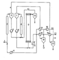
Im folgenden wird anhand der Abbildung eine kurze Verfahrensbeschreibung am Beispiel der zweistufigen direkten Aufheizung des Kohlebreies im Verfahren zum Hydrieren von Kohle gegeben:
- Die aus dem Hydrierreaktor (9) abströmenden Brüden (10) werden, nachdem sie im Heißabscheider (13) vom flüssigen Abschlamm getrennt worden sind, in der Mischstrecke (8) mit dem Kohlebrei innig vermischt, so daß sich eine Mischungstemperatur von etwa 400°C einstellt. Sodann werden Kohlebrei und Gas im Zwischenabscheider (7) getrennt.
- The vapors (10) flowing out of the hydrogenation reactor (9), after they have been separated from the liquid sludge in the hot separator (13), are intimately mixed with the coal slurry in the mixing section (8), so that a mixing temperature of about 400 ° C. sets. Then coal pulp and gas are separated in the intermediate separator (7).
Der Brei wird mit der Pumpe (6) in den Reaktor gefördert. Gleichzeitig mit dem Kohlebrei tritt der für die Hydrierung nötige Wasserstoff, nämlich Frischwasserstoff und der verfahrensbedingte Kreislaufwasserstoff in den Reaktor ein (21). Dieser Gasstrom wird unter Wärmerückgewinnung in den Wärmeaustauschern (19) und (15) aufgeheizt. Der Wärmeaustauscher (12) ist zusätzlich vorgesehen, um im Bedarfsfalle etwa erforderliche Fremdwärme zuführen zu können.The slurry is fed into the reactor with the pump (6). At the same time as the coal pulp, the hydrogen required for the hydrogenation, namely fresh hydrogen and the process-related circulating hydrogen, enters the reactor (21). This gas stream is heated with heat recovery in the heat exchangers (19) and (15). The heat exchanger (12) is additionally provided in order to be able to supply any external heat that may be required.
Das im Zwischenabscheider (7) abgetrennte Reaktorgas wird in den Wärmeaustauschern (14) und (15) im Wärmeverbund abgekühlt und nahe auf Raumtemperatur gebracht; dabei kondensiert das Kaltabscheideröl aus und kann im Kaltabscheider (16) abgetrennt werden (Strom (17)).The reactor gas separated in the intermediate separator (7) is cooled in the heat exchangers (14) and (15) in a heat network and brought close to room temperature; the cold separator oil condenses out and can be separated in the cold separator (16) (stream (17)).
Das produktfreie Gas, das im Wärmeaustauscher (14) unter Wärmerückgewinnung und - bei eventuellem Fremdwärmebedarf - im Wärmeübertrager (11) aufgeheizt wird, gelangt zur Mischstrecke (2), wo es mit dem in das System eintretenden Kohlebrei'(1) vermischt wird. Dabei wird die Maische erwärmt.The product-free gas, which is heated in the heat exchanger (14) with heat recovery and - if there is a need for external heat - in the heat exchanger (11), reaches the mixing section (2), where it is mixed with the coal pulp entering the system (1). The mash is heated.
Beispielhaft wird der Kohlebrei (1) in Stufe (2) von 100°C auf 230°C vorgewärmt, in der anderen Mischstufe (8) erfolgt dann die Aufheizung auf die notwendige Temperatur von 4000C. Durch konsequente Nutzung des Wärmeverbundes, das bedingt entsprechende Austauschflächen, kann der Bedarf an Fremdwärme auf Null gebracht werden.Illustratively, the coal slurry (1) in step is preheated (2) of 100 ° C to 230 ° C, the heating then takes place in the other mixer stage (8) to the necessary temperature of 400 0 C. With consistent use of the heating network, which conditions appropriate exchange areas, the need for external heat can be brought to zero.
Bei der Erwärmung des Kohlebreies in der Vorheizstufe (2) werden Leichtsieder, z.B. Wasser, frei, diese werden zusammen mit dem Aufheizgas im Abscheider (3) von der Maische getrennt. Während der Kohlebrei mit Hilfe der Breipumpe (5) zur Vorheizstrecke (8) gepumpt wird, geht der Gasstrom (4) unter Abkühlung im Wärmeaustauscher (19) zum Abscheider (22). Unter Raumtemperatur wird hier das auskondensierte Wasser zusammen mit anderen Leichtsiedern abgeschieden.When the coal pulp is heated in the preheating stage (2), low boilers, e.g. Water, free, these are separated from the mash together with the heating gas in the separator (3). While the pulp is pumped to the preheating section (8) with the aid of the slurry pump (5), the gas stream (4) goes to the separator (22) while cooling in the heat exchanger (19). The condensed water is separated off here together with other low boilers below room temperature.
Soll zum besseren Wärmerückgewinn der durch die Austauschstufe (2) geleitete interne Kreisgasstrom vergrößert werden, so kann hinter dem Abscheider (22) von dem Gasstrom. der zur Gasreinigung geführt werden soll, ein Teilstrom (20) abgezweigt und mit Hilfe des Kreisgaskompressors (18) über (14) und (11) zur Stufe (2) gepumpt werden.If the internal circulating gas flow passed through the exchange stage (2) is to be increased for better heat recovery, the gas flow can be removed behind the separator (22). which is to be conducted for gas purification, a partial stream (20) is branched off and pumped to stage (2) with the aid of the circulating gas compressor (18) via (14) and (11).
Zeichn.Sign.
Claims (6)
Applications Claiming Priority (2)
| Application Number | Priority Date | Filing Date | Title |
|---|---|---|---|
| DE3101598 | 1981-01-20 | ||
| DE19813101598 DE3101598A1 (en) | 1981-01-20 | 1981-01-20 | METHOD FOR HYDROGENATING COAL |
Publications (3)
| Publication Number | Publication Date |
|---|---|
| EP0056487A2 true EP0056487A2 (en) | 1982-07-28 |
| EP0056487A3 EP0056487A3 (en) | 1983-06-22 |
| EP0056487B1 EP0056487B1 (en) | 1985-11-21 |
Family
ID=6122930
Family Applications (1)
| Application Number | Title | Priority Date | Filing Date |
|---|---|---|---|
| EP81110725A Expired EP0056487B1 (en) | 1981-01-20 | 1981-12-23 | Process for the hydrogenation of coal |
Country Status (3)
| Country | Link |
|---|---|
| US (1) | US4468315A (en) |
| EP (1) | EP0056487B1 (en) |
| DE (2) | DE3101598A1 (en) |
Families Citing this family (4)
| Publication number | Priority date | Publication date | Assignee | Title |
|---|---|---|---|---|
| DE3246609A1 (en) * | 1982-12-16 | 1984-06-20 | GfK Gesellschaft für Kohleverflüssigung mbH, 6600 Saarbrücken | METHOD FOR HYDROGENATING COAL |
| DE3438330C2 (en) * | 1983-11-05 | 1987-04-30 | GfK Gesellschaft für Kohleverflüssigung mbH, 6600 Saarbrücken | Process for liquefying coal |
| DE3585485D1 (en) * | 1984-09-13 | 1992-04-09 | Ruhrkohle Ag | METHOD FOR SETTING THE PROCESS WITH HEAT RECOVERY FOR THE HUMP PHASE HYDRATION WITH INTEGRATED GAS PHASE HYDRATION. |
| CN105295990B (en) * | 2015-10-23 | 2017-10-03 | 北京中科诚毅科技发展有限公司 | A kind of method and its design method and purposes of the pretreatment of raw material of slurry bed system hydrogenation technique |
Family Cites Families (9)
| Publication number | Priority date | Publication date | Assignee | Title |
|---|---|---|---|---|
| US1876009A (en) * | 1926-02-06 | 1932-09-06 | Standard Ig Co | Conversion of solid fuels and products derived therefrom or other carbonaceous materials into valuable products |
| DE669660C (en) * | 1934-07-07 | 1938-12-31 | I G Farbenindustrie Akt Ges | Process for the production of liquid hydrocarbon oils by pressure hydrogenation of solid carbonaceous substances |
| US4113602A (en) * | 1976-06-08 | 1978-09-12 | Exxon Research & Engineering Co. | Integrated process for the production of hydrocarbons from coal or the like in which fines from gasifier are coked with heavy hydrocarbon oil |
| DE2654635B2 (en) * | 1976-12-02 | 1979-07-12 | Ludwig Dr. 6703 Limburgerhof Raichle | Process for the continuous production of hydrocarbon oils from coal by cracking pressure hydrogenation |
| DE2711105C2 (en) * | 1977-03-15 | 1984-05-24 | Saarbergwerke AG, 6600 Saarbrücken | Process for converting coal into hydrocarbons which are liquid under normal conditions |
| US4222844A (en) * | 1978-05-08 | 1980-09-16 | Exxon Research & Engineering Co. | Use of once-through treat gas to remove the heat of reaction in solvent hydrogenation processes |
| US4189375A (en) * | 1978-12-13 | 1980-02-19 | Gulf Oil Corporation | Coal liquefaction process utilizing selective heat addition |
| US4297200A (en) * | 1980-01-18 | 1981-10-27 | Briley Patrick B | Method for hydroconversion of solid carbonaceous materials |
| DE3042984C2 (en) * | 1980-11-14 | 1986-06-26 | Saarbergwerke AG, 6600 Saarbrücken | Process for hydrogenating coal |
-
1981
- 1981-01-20 DE DE19813101598 patent/DE3101598A1/en not_active Withdrawn
- 1981-12-23 EP EP81110725A patent/EP0056487B1/en not_active Expired
- 1981-12-23 DE DE8181110725T patent/DE3173032D1/en not_active Expired
-
1982
- 1982-01-07 US US06/337,682 patent/US4468315A/en not_active Expired - Fee Related
Also Published As
| Publication number | Publication date |
|---|---|
| DE3101598A1 (en) | 1982-08-26 |
| EP0056487B1 (en) | 1985-11-21 |
| EP0056487A3 (en) | 1983-06-22 |
| DE3173032D1 (en) | 1986-01-02 |
| US4468315A (en) | 1984-08-28 |
Similar Documents
| Publication | Publication Date | Title |
|---|---|---|
| DE2352561C2 (en) | Method for dissipating the compression heat that arises when compressing a gas mixture | |
| DE1592319A1 (en) | Method and apparatus for reforming hydrocarbons | |
| DD237182A5 (en) | METHOD FOR FURTHER PROCESSING OF SWIMMING GAS FROM THE WASTE PYROLYSIS | |
| DE2726302A1 (en) | PROCESS AND SYSTEM FOR WASTE WATER CLEANING | |
| DE2713359A1 (en) | PROCESS FOR THE FRACTIONATION OF CRACK GASES WITH THE HELP OF REFRIGERATION TECHNOLOGY | |
| EP0058327A2 (en) | Process for the continuous preparation of hydrocarbon oils from coal by pressure hydrogenation | |
| EP3115336A1 (en) | Method and plant for the cooling of synthesis gas | |
| EP0056487B1 (en) | Process for the hydrogenation of coal | |
| DD148640A5 (en) | COAL LIQUIDATION METHOD USING A SELECTIVE CHEMICAL SUPPLY | |
| DD147678A5 (en) | COAL LIQUIDATION METHOD WITH INTERNAL HEAT TRANSFER | |
| DE3630162A1 (en) | METHOD FOR THE PRODUCTION OF MONOMERAL VINYL CHLORIDE BY CRACKING DICHLORETHANE AND A PLANT SUITABLE FOR THIS | |
| DE3643801C2 (en) | ||
| DE2925720A1 (en) | METHOD FOR PRODUCING VINYL CHLORIDE BY THERMAL CLEAVING 1,2-DICHLORETHANE | |
| DE2554742B2 (en) | Process for the pretreatment of raw gas | |
| DE4230266A1 (en) | Method and device for heat recovery in the chemical degradation of sewage sludge or waste water | |
| DD235563A5 (en) | PROCESS FOR COOLING OR ATTACHING A GAS | |
| EP0052745B1 (en) | Process for the preparation of phthalic anhydride | |
| DE3024809A1 (en) | METHOD AND INSTALLATION FOR DESTRUCTING THE WATER COOKING AND MASH TREATMENT, AND FOR RECOVERING THE EXCESS ENERGY PROVIDED IN BEER PRODUCTION | |
| WO1982001715A1 (en) | Coal hydrogenation process | |
| DE2945352A1 (en) | METAL OF COAL HYDRATION | |
| DE3236985C2 (en) | ||
| AT398428B (en) | DEVICE FOR THERMALLY CLEAVING A MIXTURE WITH LIQUID AND GASEOUS HYDROCARBONS | |
| DE2200607A1 (en) | PROCESS FOR DIRECT COOLING OF RAW COOKING GAS | |
| DE361260C (en) | Process for evaporation of boiler feed water | |
| DE571597C (en) | Method and device for distilling petroleum |
Legal Events
| Date | Code | Title | Description |
|---|---|---|---|
| PUAI | Public reference made under article 153(3) epc to a published international application that has entered the european phase |
Free format text: ORIGINAL CODE: 0009012 |
|
| AK | Designated contracting states |
Designated state(s): BE DE FR GB IT NL |
|
| 17P | Request for examination filed |
Effective date: 19820717 |
|
| PUAL | Search report despatched |
Free format text: ORIGINAL CODE: 0009013 |
|
| AK | Designated contracting states |
Designated state(s): BE DE FR GB IT NL |
|
| GRAA | (expected) grant |
Free format text: ORIGINAL CODE: 0009210 |
|
| AK | Designated contracting states |
Designated state(s): BE DE FR GB IT NL |
|
| ITF | It: translation for a ep patent filed | ||
| REF | Corresponds to: |
Ref document number: 3173032 Country of ref document: DE Date of ref document: 19860102 |
|
| ET | Fr: translation filed | ||
| PLBE | No opposition filed within time limit |
Free format text: ORIGINAL CODE: 0009261 |
|
| STAA | Information on the status of an ep patent application or granted ep patent |
Free format text: STATUS: NO OPPOSITION FILED WITHIN TIME LIMIT |
|
| 26N | No opposition filed | ||
| PGFP | Annual fee paid to national office [announced via postgrant information from national office to epo] |
Ref country code: NL Payment date: 19861231 Year of fee payment: 6 |
|
| REG | Reference to a national code |
Ref country code: GB Ref legal event code: 732 |
|
| REG | Reference to a national code |
Ref country code: FR Ref legal event code: TP |
|
| NLS | Nl: assignments of ep-patents |
Owner name: SAARBERGWERKE AKTIENGESELLSCHAFT TE SAARBRUECKEN, |
|
| PG25 | Lapsed in a contracting state [announced via postgrant information from national office to epo] |
Ref country code: GB Effective date: 19881223 |
|
| PG25 | Lapsed in a contracting state [announced via postgrant information from national office to epo] |
Ref country code: BE Effective date: 19881231 |
|
| BERE | Be: lapsed |
Owner name: SAARBERGWERKE A.G. Effective date: 19881231 |
|
| PG25 | Lapsed in a contracting state [announced via postgrant information from national office to epo] |
Ref country code: NL Effective date: 19890701 |
|
| NLV4 | Nl: lapsed or anulled due to non-payment of the annual fee | ||
| GBPC | Gb: european patent ceased through non-payment of renewal fee | ||
| PG25 | Lapsed in a contracting state [announced via postgrant information from national office to epo] |
Ref country code: FR Free format text: LAPSE BECAUSE OF NON-PAYMENT OF DUE FEES Effective date: 19890831 |
|
| PG25 | Lapsed in a contracting state [announced via postgrant information from national office to epo] |
Ref country code: DE Effective date: 19890901 |
|
| REG | Reference to a national code |
Ref country code: FR Ref legal event code: ST |