EP0056487A2 - Procédé d'hydrogénation du charbon - Google Patents
Procédé d'hydrogénation du charbon Download PDFInfo
- Publication number
- EP0056487A2 EP0056487A2 EP81110725A EP81110725A EP0056487A2 EP 0056487 A2 EP0056487 A2 EP 0056487A2 EP 81110725 A EP81110725 A EP 81110725A EP 81110725 A EP81110725 A EP 81110725A EP 0056487 A2 EP0056487 A2 EP 0056487A2
- Authority
- EP
- European Patent Office
- Prior art keywords
- heat
- coal
- hydrogenation
- gas
- gases
- Prior art date
- Legal status (The legal status is an assumption and is not a legal conclusion. Google has not performed a legal analysis and makes no representation as to the accuracy of the status listed.)
- Granted
Links
Images
Classifications
-
- C—CHEMISTRY; METALLURGY
- C10—PETROLEUM, GAS OR COKE INDUSTRIES; TECHNICAL GASES CONTAINING CARBON MONOXIDE; FUELS; LUBRICANTS; PEAT
- C10G—CRACKING HYDROCARBON OILS; PRODUCTION OF LIQUID HYDROCARBON MIXTURES, e.g. BY DESTRUCTIVE HYDROGENATION, OLIGOMERISATION, POLYMERISATION; RECOVERY OF HYDROCARBON OILS FROM OIL-SHALE, OIL-SAND, OR GASES; REFINING MIXTURES MAINLY CONSISTING OF HYDROCARBONS; REFORMING OF NAPHTHA; MINERAL WAXES
- C10G1/00—Production of liquid hydrocarbon mixtures from oil-shale, oil-sand, or non-melting solid carbonaceous or similar materials, e.g. wood, coal
- C10G1/08—Production of liquid hydrocarbon mixtures from oil-shale, oil-sand, or non-melting solid carbonaceous or similar materials, e.g. wood, coal with moving catalysts
- C10G1/083—Production of liquid hydrocarbon mixtures from oil-shale, oil-sand, or non-melting solid carbonaceous or similar materials, e.g. wood, coal with moving catalysts in the presence of a solvent
Definitions
- the direct heat exchange between Christsdäm p fen and coal slurry would provide benefits.
- the mixing section required for direct heat exchange is less sensitive to distribution problems of the two-phase mixture, and there is no risk of cracking on overheated heat exchanger surfaces.
- the use of hydrogen as an essential component of the heat transfer gas also guarantees that the coal pulp is always heated in the presence of hydrogen.
- Direct heat exchange has also already been carried out in one step or over a limited temperature range in a countercurrent apparatus. In both cases, some of the vaporous reaction products condense out in the pulp; this limits the application of the principle of direct heat exchange to a relatively high temperature level. Extensive heat recovery through direct exchange is not possible in this way.
- the gases and vapors flowing from the reaction were cooled to a temperature not below 350 ° C., preferably to a temperature between 380 and 440 ° C., in particular 390 to 410 ° C., in a first mixing stage. Then high-boiling oils are separated in an intermediate separator. In order to achieve this temperature in the intermediate separator, a preheating section at lower temperatures is required, in which the coal slurry is preheated. With direct heat exchange, the reaction gas is cooled to temperatures lower than 350 ° C. When cooling below 350 ° C, however, an excessive amount of the reaction products would fail here and be fed back to the reactor with the coal pulp.
- reaction products in the paste and in the reaction zone is prevented by the reaction products being previously removed from the reaction gases in a cold separator at about room temperature.
- the remaining gas, freed from the oil vapor, is then heated in countercurrent with the product-laden gas flowing to the cold separator in a heat exchanger, the gas flowing to the cold separator being cooled.
- This heated gas, freed from the product can now serve as a heat carrier and supply the necessary heat to the paste in a direct heat exchange. If additional heat is required to cover a peak demand, the product-free gas can be heated with this external heat without the heat-transferring surfaces cracking or otherwise occupy themselves with carbon. '
- the advantage of the procedure according to the invention consists essentially in the fact that only clean gases enter the heat exchanger for the external heat supply, while the coal pulp is heated by direct heating in multiphase mixing sections which are considerably simpler in terms of equipment and thus cheaper, without the risk of cracking Individual pipes are laid and there is overheating on the heat exchanger surfaces.
- the coal pulp is always heated in the presence of hydrogen.
- the effect of the countercurrent principle can largely be achieved by suitable selection of the number of stages of direct heating.
- the mixing stages which are operated at temperatures below 400 ° C. and to which the heat is supplied by gas from which the product has already condensed, can also be designed as countercurrent apparatuses in order to achieve even better heat utilization.
- the advantage of the process according to the invention is that the coal pulp, which is difficult to treat, is directly mixed with gases from the process onto the reactor is brought to the temperature, the external heat supply, in contrast to a single-stage circuit, can usually be omitted entirely or at least kept significantly smaller.
- the multi-stage direct mixing is made possible by separating the gas from the product of value after the first mixing section, so that no product can fail in the colder mixing stages. It is only through the multi-stage direct mixing that the known advantages of direct heating over indirect heating in tubular bilge heat exchangers can be optimally used: With direct heating in a mixing section, the problem of distributing the coal slurry in the heat exchanger can be solved much better, especially with very large appliances with indirect heat exchange, in which dead zones can easily form, which are harmful to the product and occupy the exchange surfaces. This is the main advantage compared to indirect heat exchange in counterflow. Much simpler apparatuses than shell-and-tube heat exchangers can be used as mixing sections for direct heat exchange, especially at high pressure.
- Direct mixing makes it possible to use coal that has not been pre-dried.
- the expelled water vapor and other low boilers are not passed through the reactor, but are discharged directly via a cold separator.
- the coal Even when predried, the coal still contains a significant proportion of water, which increases the reaction pressure as steam in the reactor. In the case of direct heating, this amount of water is also removed together with the volatile constituents of the coal and of the grinding oil in front of the reactor, so that the reaction pressure can be lower by the partial pressures of these low boilers.
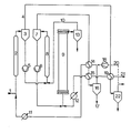
- the slurry is fed into the reactor with the pump (6).
- the hydrogen required for the hydrogenation namely fresh hydrogen and the process-related circulating hydrogen, enters the reactor (21).
- This gas stream is heated with heat recovery in the heat exchangers (19) and (15).
- the heat exchanger (12) is additionally provided in order to be able to supply any external heat that may be required.
- the reactor gas separated in the intermediate separator (7) is cooled in the heat exchangers (14) and (15) in a heat network and brought close to room temperature; the cold separator oil condenses out and can be separated in the cold separator (16) (stream (17)).
- the product-free gas which is heated in the heat exchanger (14) with heat recovery and - if there is a need for external heat - in the heat exchanger (11), reaches the mixing section (2), where it is mixed with the coal pulp entering the system (1).
- the mash is heated.
- the coal slurry (1) in step is preheated (2) of 100 ° C to 230 ° C, the heating then takes place in the other mixer stage (8) to the necessary temperature of 400 0 C.
- the heating network which conditions appropriate exchange areas, the need for external heat can be brought to zero.
- the gas flow passed through the exchange stage (2) is to be increased for better heat recovery, the gas flow can be removed behind the separator (22). which is to be conducted for gas purification, a partial stream (20) is branched off and pumped to stage (2) with the aid of the circulating gas compressor (18) via (14) and (11).
Landscapes
- Chemical & Material Sciences (AREA)
- Engineering & Computer Science (AREA)
- Oil, Petroleum & Natural Gas (AREA)
- Life Sciences & Earth Sciences (AREA)
- Wood Science & Technology (AREA)
- Chemical Kinetics & Catalysis (AREA)
- General Chemical & Material Sciences (AREA)
- Organic Chemistry (AREA)
- Paper (AREA)
- Production Of Liquid Hydrocarbon Mixture For Refining Petroleum (AREA)
- Solid Fuels And Fuel-Associated Substances (AREA)
Applications Claiming Priority (2)
| Application Number | Priority Date | Filing Date | Title |
|---|---|---|---|
| DE3101598 | 1981-01-20 | ||
| DE19813101598 DE3101598A1 (de) | 1981-01-20 | 1981-01-20 | Verfahren zum hydrieren von kohle |
Publications (3)
| Publication Number | Publication Date |
|---|---|
| EP0056487A2 true EP0056487A2 (fr) | 1982-07-28 |
| EP0056487A3 EP0056487A3 (en) | 1983-06-22 |
| EP0056487B1 EP0056487B1 (fr) | 1985-11-21 |
Family
ID=6122930
Family Applications (1)
| Application Number | Title | Priority Date | Filing Date |
|---|---|---|---|
| EP81110725A Expired EP0056487B1 (fr) | 1981-01-20 | 1981-12-23 | Procédé d'hydrogénation du charbon |
Country Status (3)
| Country | Link |
|---|---|
| US (1) | US4468315A (fr) |
| EP (1) | EP0056487B1 (fr) |
| DE (2) | DE3101598A1 (fr) |
Families Citing this family (4)
| Publication number | Priority date | Publication date | Assignee | Title |
|---|---|---|---|---|
| DE3246609A1 (de) * | 1982-12-16 | 1984-06-20 | GfK Gesellschaft für Kohleverflüssigung mbH, 6600 Saarbrücken | Verfahren zum hydrieren von kohle |
| DE3438330C2 (de) * | 1983-11-05 | 1987-04-30 | GfK Gesellschaft für Kohleverflüssigung mbH, 6600 Saarbrücken | Verfahren zum Verflüssigen von Kohle |
| EP0177676B1 (fr) * | 1984-09-13 | 1992-03-04 | Ruhrkohle Aktiengesellschaft | Réglage par récupération de la chaleur d'un procédé d'hydrogénation en suspension avec hydrogénation en phase gazeuse intégrée |
| CN105295990B (zh) * | 2015-10-23 | 2017-10-03 | 北京中科诚毅科技发展有限公司 | 一种浆态床加氢工艺的原料预处理的方法及其设计方法和用途 |
Family Cites Families (9)
| Publication number | Priority date | Publication date | Assignee | Title |
|---|---|---|---|---|
| US1876009A (en) * | 1926-02-06 | 1932-09-06 | Standard Ig Co | Conversion of solid fuels and products derived therefrom or other carbonaceous materials into valuable products |
| DE669660C (de) * | 1934-07-07 | 1938-12-31 | I G Farbenindustrie Akt Ges | Verfahren zur Herstellung von fluessigen Kohlenwasserstoffoelen durch Druckhydrierung fester kohlenstoffhaltiger Stoffe |
| US4113602A (en) * | 1976-06-08 | 1978-09-12 | Exxon Research & Engineering Co. | Integrated process for the production of hydrocarbons from coal or the like in which fines from gasifier are coked with heavy hydrocarbon oil |
| DE2654635B2 (de) * | 1976-12-02 | 1979-07-12 | Ludwig Dr. 6703 Limburgerhof Raichle | Verfahren zur kontinuierlichen Herstellung von Kohlenwasserstoffölen aus Kohle durch spaltende Druckhydrierung |
| DE2711105C2 (de) * | 1977-03-15 | 1984-05-24 | Saarbergwerke AG, 6600 Saarbrücken | Verfahren zur Umwandlung von Kohle in unter Normalbedingungen flüssige Kohlenwasserstoffe |
| US4222844A (en) * | 1978-05-08 | 1980-09-16 | Exxon Research & Engineering Co. | Use of once-through treat gas to remove the heat of reaction in solvent hydrogenation processes |
| US4189375A (en) * | 1978-12-13 | 1980-02-19 | Gulf Oil Corporation | Coal liquefaction process utilizing selective heat addition |
| US4297200A (en) * | 1980-01-18 | 1981-10-27 | Briley Patrick B | Method for hydroconversion of solid carbonaceous materials |
| DE3042984C2 (de) * | 1980-11-14 | 1986-06-26 | Saarbergwerke AG, 6600 Saarbrücken | Verfahren zum Hydrieren von Kohle |
-
1981
- 1981-01-20 DE DE19813101598 patent/DE3101598A1/de not_active Withdrawn
- 1981-12-23 DE DE8181110725T patent/DE3173032D1/de not_active Expired
- 1981-12-23 EP EP81110725A patent/EP0056487B1/fr not_active Expired
-
1982
- 1982-01-07 US US06/337,682 patent/US4468315A/en not_active Expired - Fee Related
Also Published As
| Publication number | Publication date |
|---|---|
| EP0056487B1 (fr) | 1985-11-21 |
| US4468315A (en) | 1984-08-28 |
| EP0056487A3 (en) | 1983-06-22 |
| DE3173032D1 (en) | 1986-01-02 |
| DE3101598A1 (de) | 1982-08-26 |
Similar Documents
| Publication | Publication Date | Title |
|---|---|---|
| DE2352561C2 (de) | Verfahren zum Abführen der beim Verdichten eines Gasgemisches anfallenden Kompressionswärme | |
| DE1592319A1 (de) | Verfahren und Vorrichtung zum Reformieren von Kohlenwasserstoffen | |
| DE2726302A1 (de) | Verfahren und anlage zur reinigung von abwaessern | |
| DE2713359A1 (de) | Verfahren zur fraktionierung von crackgasen mit hilfe der kaeltetechnik | |
| EP0058327A2 (fr) | Procédé de préparation en continu d'huiles hydrocarburées à partir de charbon par hydrogénation sous pression | |
| DE3441080A1 (de) | Verfahren zur aufarbeitung des pyrolyse-produkts aus der 1.2-dichlorethan-spaltung unter waermerueckgewinnung | |
| EP3115336A1 (fr) | Installation et procede de refroidissement de gaz de synthese | |
| EP0056487B1 (fr) | Procédé d'hydrogénation du charbon | |
| DE3505553C2 (de) | Verfahren zur Vorbehandlung der Einsatzprodukte für die Kohlehydrierung | |
| DD148640A5 (de) | Kohleverfluessigungsverfahren unter einsatz einer selektiven waermezufuehrung | |
| DD147678A5 (de) | Kohleverfluessigungsverfahren mit innerer waermeuebertragung | |
| DE3244143A1 (de) | Verfahren zur gaszerlegung | |
| EP0272378B1 (fr) | Procédé et dispositif pour le refroidissement de gaz de craquage | |
| DE3630162A1 (de) | Verfahren zum herstellen von monomerem vinylchlorid durch kracken von dichlorethan und hierfuer geeignete anlage | |
| DE2925720A1 (de) | Verfahren zur herstellung von vinylchlorid durch thermische spaltung von 1,2-dichlorethan | |
| DE2554742B2 (de) | Verfahren zur Vorbehandlung von Rohgas | |
| DE4230266A1 (de) | Verfahren und Vorrichtung zur Wärmerückgewinnung beim chemischen Abbau von Klärschlamm oder Abwasser | |
| EP0052745B1 (fr) | Procédé de préparation d'anhydride phtalique | |
| DE3024809A1 (de) | Verfahren und anlage zur vernichtung der bei der wuerzekochung und der maischebehandlung anfallenden schwaden sowie zur rueckgewinnung der bei der bierherstellung anfallenden ueberschussenergie | |
| DE2945352A1 (de) | Verfahren zur kohlehydrierung | |
| DE3236985C2 (fr) | ||
| AT398428B (de) | Vorrichtung zum thermischen spalten eines gemisches mit flüssigen und gasförmigen kohlenwasserstoffen | |
| DE2200607A1 (de) | Verfahren zur direkten kuehlung von rohem kokereigas | |
| DE571597C (de) | Verfahren und Vorrichtung zum Destillieren von Erdoelen | |
| DE1089918B (de) | Verfahren zur Senkung des Heizwertes von Erdgas |
Legal Events
| Date | Code | Title | Description |
|---|---|---|---|
| PUAI | Public reference made under article 153(3) epc to a published international application that has entered the european phase |
Free format text: ORIGINAL CODE: 0009012 |
|
| AK | Designated contracting states |
Designated state(s): BE DE FR GB IT NL |
|
| 17P | Request for examination filed |
Effective date: 19820717 |
|
| PUAL | Search report despatched |
Free format text: ORIGINAL CODE: 0009013 |
|
| AK | Designated contracting states |
Designated state(s): BE DE FR GB IT NL |
|
| GRAA | (expected) grant |
Free format text: ORIGINAL CODE: 0009210 |
|
| AK | Designated contracting states |
Designated state(s): BE DE FR GB IT NL |
|
| ITF | It: translation for a ep patent filed | ||
| REF | Corresponds to: |
Ref document number: 3173032 Country of ref document: DE Date of ref document: 19860102 |
|
| ET | Fr: translation filed | ||
| PLBE | No opposition filed within time limit |
Free format text: ORIGINAL CODE: 0009261 |
|
| STAA | Information on the status of an ep patent application or granted ep patent |
Free format text: STATUS: NO OPPOSITION FILED WITHIN TIME LIMIT |
|
| 26N | No opposition filed | ||
| PGFP | Annual fee paid to national office [announced via postgrant information from national office to epo] |
Ref country code: NL Payment date: 19861231 Year of fee payment: 6 |
|
| REG | Reference to a national code |
Ref country code: GB Ref legal event code: 732 |
|
| REG | Reference to a national code |
Ref country code: FR Ref legal event code: TP |
|
| NLS | Nl: assignments of ep-patents |
Owner name: SAARBERGWERKE AKTIENGESELLSCHAFT TE SAARBRUECKEN, |
|
| PG25 | Lapsed in a contracting state [announced via postgrant information from national office to epo] |
Ref country code: GB Effective date: 19881223 |
|
| PG25 | Lapsed in a contracting state [announced via postgrant information from national office to epo] |
Ref country code: BE Effective date: 19881231 |
|
| BERE | Be: lapsed |
Owner name: SAARBERGWERKE A.G. Effective date: 19881231 |
|
| PG25 | Lapsed in a contracting state [announced via postgrant information from national office to epo] |
Ref country code: NL Effective date: 19890701 |
|
| NLV4 | Nl: lapsed or anulled due to non-payment of the annual fee | ||
| GBPC | Gb: european patent ceased through non-payment of renewal fee | ||
| PG25 | Lapsed in a contracting state [announced via postgrant information from national office to epo] |
Ref country code: FR Free format text: LAPSE BECAUSE OF NON-PAYMENT OF DUE FEES Effective date: 19890831 |
|
| PG25 | Lapsed in a contracting state [announced via postgrant information from national office to epo] |
Ref country code: DE Effective date: 19890901 |
|
| REG | Reference to a national code |
Ref country code: FR Ref legal event code: ST |