EP0056518A1 - Entfernung von flüssigem Gas von den Wänden von Gasrohrleitungen - Google Patents
Entfernung von flüssigem Gas von den Wänden von Gasrohrleitungen Download PDFInfo
- Publication number
- EP0056518A1 EP0056518A1 EP81305673A EP81305673A EP0056518A1 EP 0056518 A1 EP0056518 A1 EP 0056518A1 EP 81305673 A EP81305673 A EP 81305673A EP 81305673 A EP81305673 A EP 81305673A EP 0056518 A1 EP0056518 A1 EP 0056518A1
- Authority
- EP
- European Patent Office
- Prior art keywords
- gas
- pig
- pipeline
- condensed
- flow
- Prior art date
- Legal status (The legal status is an assumption and is not a legal conclusion. Google has not performed a legal analysis and makes no representation as to the accuracy of the status listed.)
- Granted
Links
- 238000011144 upstream manufacturing Methods 0.000 claims abstract description 13
- 239000003595 mist Substances 0.000 claims abstract description 5
- 238000000034 method Methods 0.000 claims abstract description 4
- 239000007789 gas Substances 0.000 claims description 219
- VNWKTOKETHGBQD-UHFFFAOYSA-N methane Chemical compound C VNWKTOKETHGBQD-UHFFFAOYSA-N 0.000 claims description 4
- 239000003345 natural gas Substances 0.000 claims description 2
- 238000007790 scraping Methods 0.000 claims description 2
- 239000007788 liquid Substances 0.000 abstract description 25
- 239000012071 phase Substances 0.000 description 18
- 101100129922 Caenorhabditis elegans pig-1 gene Proteins 0.000 description 7
- 101100520057 Drosophila melanogaster Pig1 gene Proteins 0.000 description 7
- 230000005494 condensation Effects 0.000 description 5
- 238000009833 condensation Methods 0.000 description 5
- 238000009434 installation Methods 0.000 description 5
- 241000237858 Gastropoda Species 0.000 description 3
- 241000282887 Suidae Species 0.000 description 2
- 239000007791 liquid phase Substances 0.000 description 2
- 238000013459 approach Methods 0.000 description 1
- 230000004888 barrier function Effects 0.000 description 1
- 238000007796 conventional method Methods 0.000 description 1
- 239000007792 gaseous phase Substances 0.000 description 1
- 230000005484 gravity Effects 0.000 description 1
- 231100001261 hazardous Toxicity 0.000 description 1
- 239000013535 sea water Substances 0.000 description 1
- 239000002689 soil Substances 0.000 description 1
Images

Classifications
-
- B—PERFORMING OPERATIONS; TRANSPORTING
- B08—CLEANING
- B08B—CLEANING IN GENERAL; PREVENTION OF FOULING IN GENERAL
- B08B9/00—Cleaning hollow articles by methods or apparatus specially adapted thereto
- B08B9/02—Cleaning pipes or tubes or systems of pipes or tubes
- B08B9/027—Cleaning the internal surfaces; Removal of blockages
- B08B9/04—Cleaning the internal surfaces; Removal of blockages using cleaning devices introduced into and moved along the pipes
- B08B9/053—Cleaning the internal surfaces; Removal of blockages using cleaning devices introduced into and moved along the pipes moved along the pipes by a fluid, e.g. by fluid pressure or by suction
- B08B9/055—Cleaning the internal surfaces; Removal of blockages using cleaning devices introduced into and moved along the pipes moved along the pipes by a fluid, e.g. by fluid pressure or by suction the cleaning devices conforming to, or being conformable to, substantially the same cross-section of the pipes, e.g. pigs or moles
- B08B9/0553—Cylindrically shaped pigs
-
- B—PERFORMING OPERATIONS; TRANSPORTING
- B08—CLEANING
- B08B—CLEANING IN GENERAL; PREVENTION OF FOULING IN GENERAL
- B08B9/00—Cleaning hollow articles by methods or apparatus specially adapted thereto
- B08B9/02—Cleaning pipes or tubes or systems of pipes or tubes
- B08B9/027—Cleaning the internal surfaces; Removal of blockages
- B08B9/04—Cleaning the internal surfaces; Removal of blockages using cleaning devices introduced into and moved along the pipes
- B08B9/053—Cleaning the internal surfaces; Removal of blockages using cleaning devices introduced into and moved along the pipes moved along the pipes by a fluid, e.g. by fluid pressure or by suction
- B08B9/055—Cleaning the internal surfaces; Removal of blockages using cleaning devices introduced into and moved along the pipes moved along the pipes by a fluid, e.g. by fluid pressure or by suction the cleaning devices conforming to, or being conformable to, substantially the same cross-section of the pipes, e.g. pigs or moles
- B08B9/0558—Cleaning the internal surfaces; Removal of blockages using cleaning devices introduced into and moved along the pipes moved along the pipes by a fluid, e.g. by fluid pressure or by suction the cleaning devices conforming to, or being conformable to, substantially the same cross-section of the pipes, e.g. pigs or moles with additional jet means
Definitions
- the problem of condensation of gas on the walls of pipelines occurs particularly with pipelines used for the collection of natural gas from gas fields and the conveyance of this gas to a collection installation.
- the condensation occurs because such pipelines are operated with the gas in the pipeline under such a temperature and a pressure that the gas is in the dense phase above the thermodynamic phase envelope of the gas.
- the pipeline operator must reestablish the pressure level in the pipeline so that the pressure is again above the phase envelope. This will normally be done by reducing the rate of outflow from the pipeline whilst maintaining the rate of input. The pressure will then rise throughout the pipeline and if equilibrium were attained, the condensed gas would be taken back into the dense phase.
- equilibrium does not obtain and once gas has condensed on the wall of the pipeline it cannot be completely removed by adjustment of the pressure in the pipeline and it is for this reason that the pools and slugs of liquid can occur.
- the conventional technique for removing such liquid from a pipeline consists in launching spheres, which are a comparatively close fit in the pipeline, into the upstream end of the pipeline and these spheres are pushed through the pipeline by the gas pressure between them and each sphere sweeps a slug of liquid in front of it.
- the aim of the present invention is to enable condensed gas to be removed from the wall of a gas pipeline in such a way that after removal the gas is entrained in the main gas flow through the pipeline.
- This gas may be in the dense phase if the pipeline is operated under dense phase conditions. In this way the necessity for disposing of a slug of liquified gas at the downstream end of the pipeline is avoided.
- a pig for passage through a gas pipeline for removing condensed -gas from the wall of the pipeline and for revapourising the gas or entraining mist or droplets in the gas flow through the pipeline
- the pig comprising a body which fits in and is driven along the pipeline by differential gas pressure between the front and back of the pig, the body having condensed gas inlet means arranged to collect gas which has condensed in the pipeline and condensed gas outlet means arranged to receive the collected gas and discharge it into a flow gas duct which extends through the body of the pig so as to receive flow gas from the pipeline and discharge it in the pipeline ahead of the pig, the flow gas duct having a venturi for reducing the pressure of the gas flowing in the flow gas duct so that the condensed gas is sucked through the inlet and outlet means into the flow gas duct to be entrained by the gas flowing in the flow gas duct in the gaseous or dense phase or in the form of droplets for discharge in the pipeline ahead
- the flow gas duct comprises an axial passage extending through the body of the pig and the condensed gas outlet means leads to the venturi.
- the condensed gas outlet means leads directly from the condensed gas inlet means.
- the flow gas duct comprises at least one flow gas inlet extending inwardly from the back end of the body and adapted to accelerate gas flowing thereinto from the pipeline, and a passage, which includes the venturi and into which the condensed gas outlet means leads, the passage extending to the front end of the pig body so as to receive gas from the or each flow gas inlet to discharge it in the pipeline ahead of the pig.
- the or each flow gas inlet includes a venturi to accelerate the gas entering the or each inlet.
- the flow gas inlet comprises a tube extending into the passage.
- the front end of the tube terminates downstream of the condensed gas outlet means.
- the front end of the tube terminates upstream of the venturi in the passage.
- the condensed gas outlet means terminates upstream of the venturi in the passage.
- venturi in the or each flow gas inlet is located closer to the front end of the inlet than to the back end.
- the pig body is formed with an internal reservoir for storing condensed gas supplied by the condensed gas inlet means and for supplying the stored condensed gas to the condensed gas outlet means.
- the internal reservoir is formed in an annular space between the outer wall of the pig and the wall of the flow gas duct.
- the reservoir is provided with a weir interposed between the condensed gas inlet means and the condensed gas outlet means.
- the pig is formed at its front end between the outer wall of the pig and the flow gas duct with flow gas inlet means for supplying, flow gas to the annular space.
- the flow gas inlet means at the front of the pig comprise at least two inlets.
- a baffle is provided in the annular space to deflect gas entering at least one of the flow gas inlets.
- a condensed gas overflow duct is provided, the overflow duct extending from the front end of the pig to the back end and having a non-return valve at its back end to allow excess condensed gas entering at the front end of the overflow duct to discharge at the back end but preventing the entry of flow gas into the overflow duct at the back end.
- the condensed gas inlet means comprises at least one inlet duct disposed at the periphery of the pig.
- the condensed gas outlet means comprises at least one outlet duct leading to the flow gas duct.
- a scraper extending around the periphery of the pig for scraping the condensed gas from the wall of the pipeline and the condensed gas inlet is annular and extends around the periphery of the pig in front of the scraper.
- annular duct extending from the or each inlet rearwardly and inwardly towards the axis of the pig, the annular duct having a blind end in which, in use, the condensed gas collects, and further ducts extend from the annular duct upstream of the blind end to the passage.
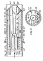
- a pipeline pig 1 has a cylindrical body 2 which is a sliding fit in a gas pipeline 3.
- the cylindrical body 2 has a part-conically tapering front end portion 4 and an annular edge 5, which forms a circular scraper, is formed around the forward end of the cylindrical body 2 at its junction with the front end portion 4.
- a central passage 6 extends axially through the body 2 and has tapering front and rear portions together forming a venturi with a throat 7.
- annular condensed gas inlet 8 is formed just within the scraper 5 and an annular duct leads rearwardly and inwardly from the -inlet 8.
- the rearward part of the annular duct 9 extends axially to a blind end 10.
- the annular duct 9 is not quite continuous in a circumferential direction, but is traversed at intervals by structural ribs which interconnect the parts of the body 2 within and surrounding the duct 9.
- a series of further radially extending ducts 11 lead from the annular duet 9 into the throat 7 of the venturi.
- the pig 1 In order to remove condensed gas 12 from the wall of the pipeline 3, which in this example is a collecting pipeline leading from an undersea gas field to a shore collecting installation and which operates under dense phase conditions, the pig 1 is inserted into the pipeline at its upstream end at the gas field.
- Gas under pressure flows through the passage 6 through the pig and there is an overall pressure drop through the passage 6 so that the gas pressure on the downstream side of the pig 1, that is the right-hand side as seen in the drawing, is less than the gas pressure at the upstream side of the pig.
- the pressure at the throat 7 of the venturi where the outlets of the ducts 11 are situated is less than the pressure in the pipeline downstream of the pig 1.
- the differential gas pressure acting on the pig 1 drives it through the pipeline in the direction of an arrow 13.
- the scraper 5 scrapes the condensed liquid 12 from the wall of the pipeline and, owing to the reduced pressure in the throat 7, this liquid is sucked through the duct 9 and through the ducts 11 whence it is discharged into the gas flow through the throat 7.
- some gas in the dense phase may be drawn with the liquified gas 12 into the annular duct 9.
- a liquid seal to form, the seal extending from the blind end 10 and covering the duct 11. Any gas finding its way past such a seal will merely be entrained and passed out at the front of the pig.
- the liquid gas which is discharged from the ducts 11 into the throat 7 is broken up in the throat by the gas stream through the passage 6 and the liquified gas may be transformed in the throat 7 by the turbulent flow conditions into the dense phase. Alternatively some of the gas may remain in the liquid phase, but this is broken up into small droplets which are dispersed in the gas flow in the pipeline 3 upstream of the pig 1.
- Any heat necessary to transform the liquified gas into the dense phase may be abstracted from the gas stream and this in turn may abstract heat from the sea water surrounding the pipeline 3 or from the soil of the sea bed upon which or in which the pipeline 3 is supported.
- the liquid can flow back through the passage 6 in the pig, but after it has flowed in this way the slug will be broken up and the liquid will no longer fill the pipe; instead the liquid will be deposited upon the wall of the pipe and a further pig can then pick up this liquid and transform it into the dense phase or disperse it in a gas flow in the manner already described.
- the pipeline pig 21 also has a cylindrical body 22, which is more elongated than that shown in Figure 1, body 22 being a sliding fit in the gas pipeline 23.
- the body 22 has a part conically tapering front end portion 24 and an annular edge 25, which forms a circular scraper, is formed around the forward end of the cylindrical body 22 at its junction with the front end portion 24.
- a central passage 26 extends axially through the body 22 with a throat 27 forming a venturi between tapering front and rear portions 28 and 29.
- the tapering rear portion 29 leads to a cylindrical rear portion 30 forming the rear of the passage 26.
- annular ' condensed gas inlet 31 is formed just within the scraper 25 and an annular condensed gas duct 32 leads rearwardly and inwardly from the inlet 31.
- the rearward part 33 of the duct 32 extends axially to a blind end 34.
- the annular duct 32 is not quite continuous in a circumferential direction, but is traversed at intervals by-structural ribs which interconnect the parts of the body 22 within and surrounding the duet 32.
- a series of further radially extending ducts 35 lead from the annular duct 32 into the cylindrical rear portion 30 of the passage 26.
- the rear end of the pig body 22 is closed by a centrally apertured disc 36 which is welded to the body 22. Extending through the disc aperture is a flow gas ejector tube 37 whose forward end terminates within the rear tapering portion 29 of the passage 26, that is, downstream of the ducts 35.
- the tube 37 is formed internally at a position close to its forward end with a restriction 38 forming a venturi.
- the pig shown in Figure 2 operates in a very similar manner to the pig shown in Figure 2 except that flow gas under pressure flows into the passage 26 by way af the ejector tube 37 but before issuing into the rear tapering portion 29 of the passage 26 the gas is caused to accelerate in the tube venturi. Condensed gas is sucked in through the ducts 32 and 35 whence it is discharged into the portion 30 of the passage 26 and is caused to be drawn towards the forward end of the tube 37. The liquid gas is then struck by the flow gas accelerated by the tube 37 and is broken up into the dense phase or as small liquid droplets. The broken up gas is then dispersed in the gas flow in the pipeline 23 ahead of the pig 21.
- the pig shown in Figure 2 is suitable for use in a 24" external diameter pipeline where the flow gas pressure is say 2000 psi.
- the overall length of the pig is not itself critical but the condensed gas inlet 31 and ducts 32 and 35 should have a flow area of 0.0031 sq. ft.
- the diameter of the venturi throat 27 should be 2.18" and the taper angle of the front tapering portion 28 should be 10° with an outlet orifice diameter of 4.63".
- the length of both the venturi throat 27 and the front tapering portion 28 should be 14".
- the overall length of the tube 37 is not -critical but the diameter of the nozzle throat restriction 38 should be 0.34" with an outlet tape angle of 10° and an outlet diameter of 0.71".
- the distance between the nozzle throat restriction 38 and the outlet or forward end of the tube 37 should be 2.11" while the distance between the forward end of the tube 37 and the upstream end of the venturi throat 27 should be 3.3".
- the above values are based on the assumption that the pig is travelling at 5ft/sec. and is removing a 1/16" film of liquid from the pipeline wall the liquid having a specific gravity of 0.6 and a molecular weight of 72.
- the pipeline pig 41 comprises a hollow generally cylindrical body 42 formed by an outer wall 43 which has a conically tapering front end portion 44.
- the pig is, as with the pigs shown in Figures 1 and 2, a sliding fit within the gas pipeline 45.
- the duct 46 forms an integral front end connection with conical end portion 44 and is formed with a flanged rear end 47 which is joined to an apertured disc 48 which closes off the rear end of the body 42.
- the duct 46 forms a venturi 49 between its tapering front and rear portions 50 and 51 respectively, a cylindrical rear portion 52 forming the rear of the duct 46.
- An upwardly and rearwardly directed inlet duct or pipe 53 for condensed gas is located between the junction between the pig body wall 43 and its front end portion 44 and forms a scraper for the condensed gas.
- the inlet pipe 53 terminates just short of the tapering front portion of the flow gas duct 46.
- the inlet pipe 53 leads to the annular space 54 between the pig body wall 43 and the flow gas duct 46, the annular space 54 forming a reservoir 55 for the condensed gas entering the pig body 42.
- the flow gas duct 46 is provided at its rear end portion 52 with three circumferentially spaced but radially directed outlet ducts or pipes 56 (as show in Figure 4) for supplying the condensed gas 57 from the reservoir 55 to the flow gas duet 46. As shown in Figures 3 and 4 the outlet pipes 56 terminate short of the outer wall 43 of the pig body 42 to permit the entry of condensed gas to the pipes 56.
- the reservoir 55 is formed with a radially directed weir 58 secured to the wall 43 of the pig 41 and positioned between the inlet pipe 53 and the outlet pipes 56 to provide a barrier to the flow of debri which accompanies the condensed gas entering the reservoir 55 via the inlet pipe 53. As shown in Figure 3 the debri 59 piles up against the weir 58.
- a flow gas ejector tube 60 extends through a central aperture in the disc 48, the ejector 60 having a forward and terminating within the rear tapering portion 51 of the flow gas duct 46, that is, downstream of the outlet pipes 56.
- the tube 60 is formed internally at a position close to its forward end with a restriction 61 forming a venturi.
- a condensed gas overflow pipe 62 which extends through the pig body 42 from its front end 44 and out through an axially offset aperture in the disc 48.
- the overflow pipe 62" is provided at its rear end 63 with a conventional non-return valve 64 permitting condensed gas to enter the pipe 62 at its front end 55 and to discharge from the pipe 62 at its rear end 63 but preventing flow gas entering the pipe 62 at its rear end 63.
- the conical front end portion 44 is also provided with a flow gas inlet 65 adjacent its junction with the wall 43 of the pig 41 and diametrically opposite to the inlet pipe 53.
- the end portion 44 is also provided with a further flow gas inlet 66 adjacent to the flow gas duct 46.
- the flow of the condensed gas 57 from the reservoir 55 through the outlet pipes 56 into the gas flow duct 46 is enhanced by the additional pressure exerted on the condensed gas 57 in the reservoir 55 by the flow gas entering the inlets 65 and 66.
- a baffle plate 67 secured to the wall 43 of the pig body 42 deflects the gas after it enters the body 42.
- the excess gas is dispersed through the overflow pipe 62 whose purpose is to transfer such excess gas from the front to the back of the pig 41 where the excess gas can be revapourised by a following pig.
Landscapes
- Physics & Mathematics (AREA)
- Fluid Mechanics (AREA)
- Engineering & Computer Science (AREA)
- Mechanical Engineering (AREA)
- Cleaning In General (AREA)
- Pipe Accessories (AREA)
- Pipeline Systems (AREA)
Applications Claiming Priority (2)
| Application Number | Priority Date | Filing Date | Title |
|---|---|---|---|
| GB8039347 | 1980-12-09 | ||
| GB8039347 | 1980-12-09 |
Publications (2)
| Publication Number | Publication Date |
|---|---|
| EP0056518A1 true EP0056518A1 (de) | 1982-07-28 |
| EP0056518B1 EP0056518B1 (de) | 1984-08-08 |
Family
ID=10517841
Family Applications (1)
| Application Number | Title | Priority Date | Filing Date |
|---|---|---|---|
| EP81305673A Expired EP0056518B1 (de) | 1980-12-09 | 1981-12-02 | Entfernung von flüssigem Gas von den Wänden von Gasrohrleitungen |
Country Status (6)
| Country | Link |
|---|---|
| US (1) | US4411039A (de) |
| EP (1) | EP0056518B1 (de) |
| JP (1) | JPS5933435B2 (de) |
| CA (1) | CA1164366A (de) |
| DE (1) | DE3165450D1 (de) |
| NO (1) | NO153556C (de) |
Cited By (3)
| Publication number | Priority date | Publication date | Assignee | Title |
|---|---|---|---|---|
| FR2517416A1 (fr) * | 1981-12-02 | 1983-06-03 | Pipeline Service Sa | Procede de sechage par le vide de canalisations |
| DE19809191C1 (de) * | 1998-03-04 | 1999-05-27 | Linde Ag | Vorrichtung zum Entfernen von Kriechfilm, insbesondere von Laugekriechfilm, an den Wänden von Gas-führenden Rohrleitungen |
| RU207193U1 (ru) * | 2021-06-15 | 2021-10-15 | Федеральное государственное бюджетное образовательное учреждение высшего образования "Ульяновский государственный аграрный университет имени П.А. Столыпина" | Устройство для очистки вакуумированных молокопроводов доильных установок |
Families Citing this family (12)
| Publication number | Priority date | Publication date | Assignee | Title |
|---|---|---|---|---|
| US4498932A (en) * | 1983-12-14 | 1985-02-12 | Shell Oil Company | Pipeline pig with restricted fluid bypass |
| JP2625533B2 (ja) * | 1987-06-19 | 1997-07-02 | ザ ユニヴァーシティ オヴ メルボルン | 注入ポンプとその駆動システム |
| US5795402A (en) * | 1995-07-25 | 1998-08-18 | Hargett, Sr.; Daniel | Apparatus and method for removal of paraffin deposits in pipeline systems |
| US6755916B1 (en) | 2002-06-14 | 2004-06-29 | Tdw Delaware, Inc. | Method of dispensing inhibitor in a gas pipeline |
| DE202006000969U1 (de) * | 2006-01-20 | 2007-05-24 | Rosen Swiss Ag | Reinigungsmolch |
| US7827646B2 (en) * | 2008-02-08 | 2010-11-09 | Tdw Delaware, Inc. | Vortex inhibitor dispersal pig |
| US8650694B2 (en) * | 2008-07-03 | 2014-02-18 | Tdw Delaware, Inc | Speed regulated pipeline pig |
| US8479345B2 (en) * | 2009-08-12 | 2013-07-09 | Tdw Delaware, Inc. | Speed control drive section with failsafe valve |
| US8151483B2 (en) | 2010-07-06 | 2012-04-10 | Tdw Delaware, Inc. | Progressive dewatering and inhibitor dispersal rolling pig |
| CN110883029A (zh) * | 2019-12-19 | 2020-03-17 | 江苏福吉特管业有限公司 | 一种油气管道引射干燥清管器 |
| US11609158B2 (en) * | 2020-09-10 | 2023-03-21 | Saudi Arabian Oil Company | Pipeline sampling scraper to sample hydrocarbon deposits while traveling in pipelines |
| US12392444B2 (en) | 2021-04-26 | 2025-08-19 | Conocophillips Company | Stabilization of flow by moveable choke |
Citations (3)
| Publication number | Priority date | Publication date | Assignee | Title |
|---|---|---|---|---|
| DE2015745A1 (de) * | 1969-04-10 | 1970-10-15 | Powers, Marvin Dewy, Houston, Tex. (V.St.A.) | Putzvorrichtung für Rohrleitungen |
| FR2089194A5 (de) * | 1970-04-06 | 1972-01-07 | Powers Marvin | |
| US3708819A (en) * | 1970-06-05 | 1973-01-09 | M Breston | Apparatus for drying pipelines |
-
1981
- 1981-12-02 EP EP81305673A patent/EP0056518B1/de not_active Expired
- 1981-12-02 DE DE8181305673T patent/DE3165450D1/de not_active Expired
- 1981-12-08 NO NO814176A patent/NO153556C/no unknown
- 1981-12-08 CA CA000391780A patent/CA1164366A/en not_active Expired
- 1981-12-09 JP JP56199470A patent/JPS5933435B2/ja not_active Expired
- 1981-12-09 US US06/329,064 patent/US4411039A/en not_active Expired - Lifetime
Patent Citations (3)
| Publication number | Priority date | Publication date | Assignee | Title |
|---|---|---|---|---|
| DE2015745A1 (de) * | 1969-04-10 | 1970-10-15 | Powers, Marvin Dewy, Houston, Tex. (V.St.A.) | Putzvorrichtung für Rohrleitungen |
| FR2089194A5 (de) * | 1970-04-06 | 1972-01-07 | Powers Marvin | |
| US3708819A (en) * | 1970-06-05 | 1973-01-09 | M Breston | Apparatus for drying pipelines |
Cited By (3)
| Publication number | Priority date | Publication date | Assignee | Title |
|---|---|---|---|---|
| FR2517416A1 (fr) * | 1981-12-02 | 1983-06-03 | Pipeline Service Sa | Procede de sechage par le vide de canalisations |
| DE19809191C1 (de) * | 1998-03-04 | 1999-05-27 | Linde Ag | Vorrichtung zum Entfernen von Kriechfilm, insbesondere von Laugekriechfilm, an den Wänden von Gas-führenden Rohrleitungen |
| RU207193U1 (ru) * | 2021-06-15 | 2021-10-15 | Федеральное государственное бюджетное образовательное учреждение высшего образования "Ульяновский государственный аграрный университет имени П.А. Столыпина" | Устройство для очистки вакуумированных молокопроводов доильных установок |
Also Published As
| Publication number | Publication date |
|---|---|
| CA1164366A (en) | 1984-03-27 |
| JPS57122984A (en) | 1982-07-31 |
| NO153556C (no) | 1986-04-16 |
| EP0056518B1 (de) | 1984-08-08 |
| NO814176L (no) | 1982-06-10 |
| NO153556B (no) | 1986-01-06 |
| JPS5933435B2 (ja) | 1984-08-15 |
| DE3165450D1 (en) | 1984-09-13 |
| US4411039A (en) | 1983-10-25 |
Similar Documents
| Publication | Publication Date | Title |
|---|---|---|
| EP0056518A1 (de) | Entfernung von flüssigem Gas von den Wänden von Gasrohrleitungen | |
| US5248421A (en) | Spiral fluid separator | |
| US3512651A (en) | Device for removing solid particles from liquid | |
| US3289608A (en) | Separating device | |
| US3885934A (en) | Centrifugal tuyere for gas separator | |
| EP0330490B1 (de) | Vakuum-Abwassersystem, Auffangbehälter dafür und Fahrzeug, das ein solches System enthält | |
| WO1985005295A1 (en) | Movable hydrodynamic nozzle for pressurized water cleaning of water, discharge and surface water pipes | |
| EP0659948B1 (de) | Druckluftgetriebene Vakkum-Abwasservorrichtung | |
| BRPI0608704B1 (pt) | dispositivo em conexão com um separador de tubo | |
| BG61598B1 (bg) | Сепаратор за разделяне на течност и газ | |
| US2847087A (en) | Dust collectors | |
| US4135574A (en) | Device for recovering cleaning elements from a heat-exchanger stream | |
| SE502765C2 (sv) | Separator | |
| WO2002100515A2 (en) | A system for separating an entrained immiscible liquid component from a wet gas stream | |
| GB2090642A (en) | Removal of Condensed Gas from the Walls of Gas Pipelines | |
| US6508261B1 (en) | Tubular line kiting system | |
| SE510471C2 (sv) | Förfarande och anordning för att hämma uppkkomsten av korrosion i en ledningskrets för en kontinuerligt strömmande systemvätska | |
| US1232464A (en) | Dust-separator. | |
| JP2544372B2 (ja) | 局所除塵方法 | |
| JPS6326046B2 (de) | ||
| SU1489810A1 (ru) | Устройство дл очистки и охлаждени газа | |
| US1901791A (en) | Means for removing dust such as from plant fired by pulverulent fuel | |
| RU2342973C1 (ru) | Устройство для очистки пара или газа от инородных включений (варианты) | |
| RU2048207C1 (ru) | Циклон а.с.карпенко | |
| US6176889B1 (en) | Apparatus for separating droplets and/or solid particles from gas |
Legal Events
| Date | Code | Title | Description |
|---|---|---|---|
| PUAI | Public reference made under article 153(3) epc to a published international application that has entered the european phase |
Free format text: ORIGINAL CODE: 0009012 |
|
| AK | Designated contracting states |
Designated state(s): DE FR IT |
|
| 17P | Request for examination filed |
Effective date: 19820619 |
|
| ITF | It: translation for a ep patent filed | ||
| GRAA | (expected) grant |
Free format text: ORIGINAL CODE: 0009210 |
|
| AK | Designated contracting states |
Designated state(s): DE FR IT |
|
| REF | Corresponds to: |
Ref document number: 3165450 Country of ref document: DE Date of ref document: 19840913 |
|
| ET | Fr: translation filed | ||
| PLBE | No opposition filed within time limit |
Free format text: ORIGINAL CODE: 0009261 |
|
| STAA | Information on the status of an ep patent application or granted ep patent |
Free format text: STATUS: NO OPPOSITION FILED WITHIN TIME LIMIT |
|
| 26N | No opposition filed | ||
| REG | Reference to a national code |
Ref country code: FR Ref legal event code: TP |
|
| ITTA | It: last paid annual fee | ||
| PGFP | Annual fee paid to national office [announced via postgrant information from national office to epo] |
Ref country code: FR Payment date: 19981110 Year of fee payment: 18 |
|
| PGFP | Annual fee paid to national office [announced via postgrant information from national office to epo] |
Ref country code: DE Payment date: 19981125 Year of fee payment: 18 |
|
| PG25 | Lapsed in a contracting state [announced via postgrant information from national office to epo] |
Ref country code: FR Free format text: LAPSE BECAUSE OF NON-PAYMENT OF DUE FEES Effective date: 20000831 |
|
| PG25 | Lapsed in a contracting state [announced via postgrant information from national office to epo] |
Ref country code: DE Free format text: LAPSE BECAUSE OF NON-PAYMENT OF DUE FEES Effective date: 20001003 |
|
| REG | Reference to a national code |
Ref country code: FR Ref legal event code: ST |