EP0056532A1 - Vorrichtung und Verfahren zum diagonalen Einstellen einer Offset-Druckmaschine und Druckmaschine mit dieser Vorrichtung - Google Patents
Vorrichtung und Verfahren zum diagonalen Einstellen einer Offset-Druckmaschine und Druckmaschine mit dieser Vorrichtung Download PDFInfo
- Publication number
- EP0056532A1 EP0056532A1 EP19810400066 EP81400066A EP0056532A1 EP 0056532 A1 EP0056532 A1 EP 0056532A1 EP 19810400066 EP19810400066 EP 19810400066 EP 81400066 A EP81400066 A EP 81400066A EP 0056532 A1 EP0056532 A1 EP 0056532A1
- Authority
- EP
- European Patent Office
- Prior art keywords
- plate
- cylinder
- blanket
- blanket cylinder
- printing machine
- Prior art date
- Legal status (The legal status is an assumption and is not a legal conclusion. Google has not performed a legal analysis and makes no representation as to the accuracy of the status listed.)
- Granted
Links
- 238000000034 method Methods 0.000 title claims abstract description 10
- 238000007645 offset printing Methods 0.000 title claims description 7
- 238000007639 printing Methods 0.000 title abstract description 9
- 230000007246 mechanism Effects 0.000 claims description 5
- 238000006073 displacement reaction Methods 0.000 claims description 3
- 230000007547 defect Effects 0.000 description 6
- 230000002159 abnormal effect Effects 0.000 description 1
- 230000002411 adverse Effects 0.000 description 1
- 230000005540 biological transmission Effects 0.000 description 1
- 238000009434 installation Methods 0.000 description 1
- 239000010985 leather Substances 0.000 description 1
- 238000005461 lubrication Methods 0.000 description 1
- 210000000056 organ Anatomy 0.000 description 1
- 230000002028 premature Effects 0.000 description 1
- 238000009736 wetting Methods 0.000 description 1
Images

Classifications
-
- B—PERFORMING OPERATIONS; TRANSPORTING
- B41—PRINTING; LINING MACHINES; TYPEWRITERS; STAMPS
- B41F—PRINTING MACHINES OR PRESSES
- B41F13/00—Common details of rotary presses or machines
- B41F13/08—Cylinders
- B41F13/24—Cylinder-tripping devices; Cylinder-impression adjustments
- B41F13/26—Arrangement of cylinder bearings
- B41F13/28—Bearings mounted eccentrically of the cylinder axis
Definitions
- the present invention relates to a "crooked" correction method in an offset printing machine; it also relates to the device used for this purpose, and to a printing machine comprising such a device.
- the plate or plate is fixed on a cylinder called plate cylinder, where it is wet and inked by contact with rollers themselves in contact with distribution rollers.
- the ink selectively deposited on the plate is distributed over an intermediate cylinder called the blanket cylinder, and from there is deposited on the sheet of paper which passes in contact with the blanket cylinder.
- the blanket cylinder is normally strictly parallel. If the printing takes place on only one side of the paper, the sheet is applied in contact with the blanket by a pressure counter-cylinder; very frequently for two-sided printing machines, another inking assembly with plate cylinder and blanket is arranged approximately symmetrically with respect to the first, and the sheet circulates between the two blanket cylinders, each providing back pressure for the other.
- the plate plate is fixed and tensioned by a usual device arranged according to a generator of the plate cylinder.
- the machines include a device for adjusting the circumferential and lateral register, allowing an angular and axial relative offset of the plate cylinder with respect to the general drive kinematic chain of the machine, so as to allow in particular the color identification on machines with several printing positions.
- the bearings of the plate cylinders generally include the mechanisms for adjusting the circumferential and lateral locations, mechanisms which are already bulky, so that it proves difficult and complex, and consequently expensive to add an additional device for biasing by independent movement of one of the bearings.
- the skew movement of the plate cylinder causes un.dégégage contact of the ink rollers and wetters, and to remedy this new drawback it would be necessary to introduce other devices again bulky and expensive.
- the present invention provides a new solution for the correction on the fly of the consequences of a "skewed" defect in photographs.
- the invention relates to a method for correcting "wrong" in a rotary offset printing machine having at least one set t a cliché plate support plate cylinder and a blanket cylinder in contact with the sheet to be printed, a process intended to compensate a slight misalignment of the plate formed on the plate.
- action is taken by angularly displacing the axis of the blanket cylinder with respect to the axis of the plate cylinder, this displacement being effected substantially in a plane perpendicular to the plane containing the two parallel axes in their normal mean position.
- the invention also relates to a device for setting work of this correction process, applied to a machine where the journals of the blanket cylinders are carried by eccentric bearings associated with a device for controlling the rotation of these eccentric bearings, to separate or bring the blanket closer to the sheet to be printed.
- the eccentric bearings of the blanket cylinders are themselves each carried by an eccentric sleeve engaged in a bore of the frame; for each cylinder blanket the eccentric sleeve on one of the journals is held fixed in the frame, while the other T is associated with a controlled rotating mechanism, the relative positions of the centers of the eccentric components of the socket being determined so that in the normal range of movement, the movement of the axis of the blanket cylinder can remain comparable to a movement in a plane perpendicular to the plane defined by the parallel axes of the blanket cylinder and the plate cylinder in the normal normal position .
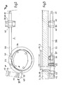
- the blanket cylinder 4 is carried by the bearings 16 and 17, each each engaged in an eccentric housing 18 and 19. Similarly, the blanket support bearings 3 are held in the eccentric housings 20 and 21.
- This mounting on the eccentric housing constitutes a usual arrangement on such machines, and is used to be able to pressurize the blanket cylinders for example when the machine stops.
- a control device (not shown) simultaneously rotates the two housings of each of the pins to produce a movement of spacing or parallel approaching of the cylinders relative to one another.
- the device can also be used to adjust the pressure of the blanket cylinders against each other according to the characteristics of the printed sheet.
- each of the eccentric housings 18, 19, 20 and 21 of the blanket cylinder bearings is itself included in another eccentric sleeve respectively 24, 25, 26 and 27, each engaged in a bore of the frames 1 or 2.
- the sockets 24 and 26 are locked in rotation in the frame 1 by screws between leather and flesh 29 and 30.
- the eccentric sockets 25 and 27 can be operated in rotation by a device more visible in Figures 2 and 3. We have shown in these two figures that the device for the cylinder 4, but of course, the other blanket cylinder 3 is provided with a control device identical in all respects .
- a part 32 in the form of an annular sector is fixed by screws 33 to the external flange 34 of the sleeve 25.
- the part 32 has a countersink which forms a yoke with the flange 34, and a threaded nut 36 is held captive in the yoke while remaining freely articulated on pins engaged in corresponding bores of the part 32 and the flange 34.
- the threaded end 37 of a control rod 38 is engaged in the nut 36; the rod 38, which can rotate freely in the bore of a support 39 fixed to the frame, is blocked in axial movement by two rings 40 which respectively come into abutment on one or the other face of the support 39.
- the relative position of the centers of the eccentric elements of the sleeve is determined so that in the normal range of movement the movement of the cylinder axis can be assimilated to a movement in a plane perpendicular to the plane defined by the axes of the blanket cylinder and the plate cylinder in the normal position.
- the angular displacement of the blanket cylinder resulting from the rotation of the sleeve 25 is such that the distances between cylinders are preserved, so that the pressure setting of the plate cylinder on the blanket or of the blanket on the sheet are not not affected.
- the invention is not strictly limited to the embodiment which has been described by way of example, but it also covers the embodiments which would differ from it only in details, in variant embodiments or in the use of equivalent means.
- the invention applies in the same way whether it is a double-sided or single-sided offset printing machine, the devices used being identical for each blanket cylinder in the case of a machine both sides.
Landscapes
- Engineering & Computer Science (AREA)
- Mechanical Engineering (AREA)
- Rotary Presses (AREA)
Priority Applications (2)
| Application Number | Priority Date | Filing Date | Title |
|---|---|---|---|
| DE8181400066T DE3165298D1 (en) | 1981-01-19 | 1981-01-19 | Method and means for diagonal adjustment in an offset-printing machine, and printing machine produced with said means |
| EP19810400066 EP0056532B1 (de) | 1981-01-19 | 1981-01-19 | Vorrichtung und Verfahren zum diagonalen Einstellen einer Offset-Druckmaschine und Druckmaschine mit dieser Vorrichtung |
Applications Claiming Priority (1)
| Application Number | Priority Date | Filing Date | Title |
|---|---|---|---|
| EP19810400066 EP0056532B1 (de) | 1981-01-19 | 1981-01-19 | Vorrichtung und Verfahren zum diagonalen Einstellen einer Offset-Druckmaschine und Druckmaschine mit dieser Vorrichtung |
Publications (2)
| Publication Number | Publication Date |
|---|---|
| EP0056532A1 true EP0056532A1 (de) | 1982-07-28 |
| EP0056532B1 EP0056532B1 (de) | 1984-08-08 |
Family
ID=8188497
Family Applications (1)
| Application Number | Title | Priority Date | Filing Date |
|---|---|---|---|
| EP19810400066 Expired EP0056532B1 (de) | 1981-01-19 | 1981-01-19 | Vorrichtung und Verfahren zum diagonalen Einstellen einer Offset-Druckmaschine und Druckmaschine mit dieser Vorrichtung |
Country Status (2)
| Country | Link |
|---|---|
| EP (1) | EP0056532B1 (de) |
| DE (1) | DE3165298D1 (de) |
Cited By (1)
| Publication number | Priority date | Publication date | Assignee | Title |
|---|---|---|---|---|
| EP0264830A3 (de) * | 1986-10-17 | 1989-02-15 | Akira Hayashi | Schallerzeugende Membran |
Citations (2)
| Publication number | Priority date | Publication date | Assignee | Title |
|---|---|---|---|---|
| CH382766A (de) * | 1959-04-08 | 1964-10-15 | Maschf Augsburg Nuernberg Ag | Einrichtung zum Einstellen der Zylinder von Offsetmaschinen |
| US3817173A (en) * | 1971-09-13 | 1974-06-18 | Polygraph Leipzig | Diagonal register adjustment of plate cylinder and applicator rolls in a rotary printing machine |
-
1981
- 1981-01-19 EP EP19810400066 patent/EP0056532B1/de not_active Expired
- 1981-01-19 DE DE8181400066T patent/DE3165298D1/de not_active Expired
Patent Citations (2)
| Publication number | Priority date | Publication date | Assignee | Title |
|---|---|---|---|---|
| CH382766A (de) * | 1959-04-08 | 1964-10-15 | Maschf Augsburg Nuernberg Ag | Einrichtung zum Einstellen der Zylinder von Offsetmaschinen |
| US3817173A (en) * | 1971-09-13 | 1974-06-18 | Polygraph Leipzig | Diagonal register adjustment of plate cylinder and applicator rolls in a rotary printing machine |
Cited By (1)
| Publication number | Priority date | Publication date | Assignee | Title |
|---|---|---|---|---|
| EP0264830A3 (de) * | 1986-10-17 | 1989-02-15 | Akira Hayashi | Schallerzeugende Membran |
Also Published As
| Publication number | Publication date |
|---|---|
| EP0056532B1 (de) | 1984-08-08 |
| DE3165298D1 (en) | 1984-09-13 |
Similar Documents
| Publication | Publication Date | Title |
|---|---|---|
| EP0305235B1 (de) | Abnehmbare Druckeinheit für Offsetdruckmaschinen | |
| US20120312179A1 (en) | Intaglio printing press with ink-collecting cylinder | |
| FR2744389A1 (fr) | Groupe d'impression permettant un changement de plaques d'impression en marche | |
| FR2588211A1 (fr) | Tambour de transfert de feuilles pour une machine rotative d'impression | |
| FR2735419A1 (fr) | Dispositif d'entrainement direct pour une machine d'impression | |
| FR2613984A1 (fr) | Presse a imprimer rotative a feuilles pour impression en plusieurs couleurs | |
| JPH0667617B2 (ja) | 枚葉紙輪転印刷機のドラム又は胴のための伝動装置 | |
| US3769910A (en) | Movably positionable cylinder arrangement for indirect printing presses | |
| EP0056532B1 (de) | Vorrichtung und Verfahren zum diagonalen Einstellen einer Offset-Druckmaschine und Druckmaschine mit dieser Vorrichtung | |
| US3593662A (en) | Cylinder arrangement for an offset litho machine | |
| FR2694233A1 (fr) | Cylindre intermédiaire d'une presse à alimentation par feuilles. | |
| US3065690A (en) | Plate cylinder mountings for printing presses | |
| EP1754599B1 (de) | Druckeinheit mit einem druckan- bzw. druckabstellbaren Gummizylinder und entsprechende Druckmaschine | |
| FR2469283A1 (fr) | Procede et dispositif de correction dite " de travers " dans une machine a imprimer offset, et machine a imprimer comportant un tel dispositif | |
| FR2639581A1 (fr) | Chariot porte-groupe d'impression pour une station d'impression dans des machines rotatives | |
| EP1167027B1 (de) | Zylindervorrichtung für eine Rotationsdruckmaschine | |
| KR20030028431A (ko) | 인쇄장치에서의 롤 지지구조 | |
| CA2096758C (en) | Device for the fastening and positional changing of a cylinder covering | |
| JPH09177903A (ja) | 印刷装置における遊びを除去するための装置 | |
| KR100232909B1 (ko) | 고무통의 인쇄압을 가하고 제거하기 위한 장치 | |
| EP2121326B1 (de) | Zahnradgetriebene druckmaschine mit variabler abstellung | |
| FR2538760A1 (fr) | Mecanisme d'encrage pour machines a imprimer rotatives | |
| FR2695872A1 (fr) | Dispositif de retournement, de format réglable, avec roues de changement, monté sur une machine rotative à imprimer des feuilles. | |
| CA2074673C (en) | Blanket to blanket type printing press employing divided plate cylinder | |
| FR2504058A1 (fr) | Dispositif pour l'ajustement en diagonale d'un cylindre de presse d'impression |
Legal Events
| Date | Code | Title | Description |
|---|---|---|---|
| PUAI | Public reference made under article 153(3) epc to a published international application that has entered the european phase |
Free format text: ORIGINAL CODE: 0009012 |
|
| 17P | Request for examination filed |
Effective date: 19811028 |
|
| AK | Designated contracting states |
Designated state(s): BE CH DE GB |
|
| GRAA | (expected) grant |
Free format text: ORIGINAL CODE: 0009210 |
|
| AK | Designated contracting states |
Designated state(s): BE CH DE GB LI |
|
| REF | Corresponds to: |
Ref document number: 3165298 Country of ref document: DE Date of ref document: 19840913 |
|
| PGFP | Annual fee paid to national office [announced via postgrant information from national office to epo] |
Ref country code: DE Payment date: 19850328 Year of fee payment: 5 |
|
| PLBE | No opposition filed within time limit |
Free format text: ORIGINAL CODE: 0009261 |
|
| STAA | Information on the status of an ep patent application or granted ep patent |
Free format text: STATUS: NO OPPOSITION FILED WITHIN TIME LIMIT |
|
| 26N | No opposition filed | ||
| PG25 | Lapsed in a contracting state [announced via postgrant information from national office to epo] |
Ref country code: LI Effective date: 19880131 Ref country code: CH Effective date: 19880131 |
|
| BERE | Be: lapsed |
Owner name: CREUSOT-LOIRE Effective date: 19880131 |
|
| GBPC | Gb: european patent ceased through non-payment of renewal fee | ||
| REG | Reference to a national code |
Ref country code: CH Ref legal event code: PL |
|
| PG25 | Lapsed in a contracting state [announced via postgrant information from national office to epo] |
Ref country code: DE Effective date: 19881001 |
|
| REG | Reference to a national code |
Ref country code: CH Ref legal event code: AUV Free format text: TOMBE EN DECHEANCE 23.08.1988 FAUTE DE PAIEMENT, DE LA 8E ANNUITE. |
|
| PG25 | Lapsed in a contracting state [announced via postgrant information from national office to epo] |
Ref country code: GB Free format text: LAPSE BECAUSE OF NON-PAYMENT OF DUE FEES Effective date: 19881121 |
|
| PG25 | Lapsed in a contracting state [announced via postgrant information from national office to epo] |
Ref country code: BE Effective date: 19890131 |