EP0056538A1 - Verschlusseinrichtung an den Enden einer Blech behandelnden Maschine - Google Patents
Verschlusseinrichtung an den Enden einer Blech behandelnden Maschine Download PDFInfo
- Publication number
- EP0056538A1 EP0056538A1 EP81401949A EP81401949A EP0056538A1 EP 0056538 A1 EP0056538 A1 EP 0056538A1 EP 81401949 A EP81401949 A EP 81401949A EP 81401949 A EP81401949 A EP 81401949A EP 0056538 A1 EP0056538 A1 EP 0056538A1
- Authority
- EP
- European Patent Office
- Prior art keywords
- machine
- flap
- frame
- flaps
- inlet
- Prior art date
- Legal status (The legal status is an assumption and is not a legal conclusion. Google has not performed a legal analysis and makes no representation as to the accuracy of the status listed.)
- Granted
Links
- 239000000463 material Substances 0.000 title description 2
- 230000000295 complement effect Effects 0.000 claims description 7
- 239000012530 fluid Substances 0.000 claims description 4
- 238000007789 sealing Methods 0.000 claims description 4
- 238000010276 construction Methods 0.000 abstract description 4
- 230000006978 adaptation Effects 0.000 abstract description 2
- 238000001816 cooling Methods 0.000 description 3
- 239000002184 metal Substances 0.000 description 3
- 235000021183 entrée Nutrition 0.000 description 2
- 239000007788 liquid Substances 0.000 description 2
- 229910000906 Bronze Inorganic materials 0.000 description 1
- 241001644893 Entandrophragma utile Species 0.000 description 1
- 239000010974 bronze Substances 0.000 description 1
- 239000012809 cooling fluid Substances 0.000 description 1
- 239000000110 cooling liquid Substances 0.000 description 1
- KUNSUQLRTQLHQQ-UHFFFAOYSA-N copper tin Chemical compound [Cu].[Sn] KUNSUQLRTQLHQQ-UHFFFAOYSA-N 0.000 description 1
- 238000006073 displacement reaction Methods 0.000 description 1
- 230000000694 effects Effects 0.000 description 1
- 210000004907 gland Anatomy 0.000 description 1
- 238000000034 method Methods 0.000 description 1
Images

Classifications
-
- B—PERFORMING OPERATIONS; TRANSPORTING
- B21—MECHANICAL METAL-WORKING WITHOUT ESSENTIALLY REMOVING MATERIAL; PUNCHING METAL
- B21B—ROLLING OF METAL
- B21B45/00—Devices for surface or other treatment of work, specially combined with or arranged in, or specially adapted for use in connection with, metal-rolling mills
- B21B45/02—Devices for surface or other treatment of work, specially combined with or arranged in, or specially adapted for use in connection with, metal-rolling mills for lubricating, cooling, or cleaning
- B21B45/0203—Cooling
- B21B45/0209—Cooling devices, e.g. using gaseous coolants
- B21B45/0215—Cooling devices, e.g. using gaseous coolants using liquid coolants, e.g. for sections, for tubes
- B21B45/0218—Cooling devices, e.g. using gaseous coolants using liquid coolants, e.g. for sections, for tubes for strips, sheets, or plates
-
- C—CHEMISTRY; METALLURGY
- C21—METALLURGY OF IRON
- C21D—MODIFYING THE PHYSICAL STRUCTURE OF FERROUS METALS; GENERAL DEVICES FOR HEAT TREATMENT OF FERROUS OR NON-FERROUS METALS OR ALLOYS; MAKING METAL MALLEABLE, e.g. BY DECARBURISATION OR TEMPERING
- C21D9/00—Heat treatment, e.g. annealing, hardening, quenching or tempering, adapted for particular articles; Furnaces therefor
- C21D9/52—Heat treatment, e.g. annealing, hardening, quenching or tempering, adapted for particular articles; Furnaces therefor for wires; for strips ; for rods of unlimited length
- C21D9/54—Furnaces for treating strips or wire
- C21D9/56—Continuous furnaces for strip or wire
- C21D9/573—Continuous furnaces for strip or wire with cooling
Definitions
- the present invention relates to machines for treating and in particular cooling sheets or other similar products, of the type comprising a lower frame and an upper frame in which are mounted sets of rollers for driving and guiding the sheet, operating in pairs. , the two frames delimiting an enclosure in which a treatment fluid circulates.
- Such a machine is described in particular in French patent n ° 73 10 710 of March 26, 1973 and in French patents n ° 77 39 833,77 39 834, 77 39 835, 77 39 836 filed on December 30, 1977.
- French patent n ° 77 39 835 relates to the arrangement of the inlet and outlet ends of such a machine and describes the presence at each of these ends of at least one flap articulated around an axis parallel to the plane of the sheet and transverse with respect to the direction of movement of this sheet, this flap being able to be brought to the high position or to the low position by means of jacks, depending on whether or not the machine has to be crossed by a sheet or other product to be treated.
- the object of this invention is to provide an arrangement of the inlet and outlet ends of a sheet processing machine, which does not have these drawbacks and which is therefore of lighter and more economical construction, less bulky and which authorizes an adaptation according to the width of the product to be treated.
- the subject of the invention is a device for closing the inlet and outlet ends of a machine for treating sheets or the like, this machine comprising an upper frame and a lower frame delimiting an enclosure in which can circulate a treatment fluid, characterized in that it comprises, for each end of the machine, at least one rigid shutter flap carried by one of the frames, guide means provided on this frame and allowing movement of the or of each flap in a direction approximately perpendicular to the plane of the sheet metal passing through the machine and of the actuation means of the or each flap, the or each flap cooperating by its free edge with the other frame to close so practically sealed the relevant end of the machine.
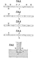
- FIG. 1 the inlet end of a plate cooling machine comprising an upper frame 10 and a lower frame 20.
- Each frame has side walls 11,21 connected by metal envelopes 12,22 comprising roughly flat parts 12a, 22a parallel to the sheet to spend in the machine and the curved portions 12b, 22b which surround the drive and guide rollers 13, 23.
- the metal sheaths delimit a chamber in which may circulate a cooling liquid, the 'enclosure being for this purpose connected to the inlet and outlet conduits of this liquid, the conduits 14,24 shown in the drawing being in this case the outlet conduits.
- the side walls 11 of the upper frame are connected by a beam 30 which in the example shown has a box structure, and whose horizontal upper wall 31 has an extension 32 directed towards the interior of the machine.
- the closure device In the space between this transverse beam and the adjacent envelope 12 b delimiting the enclosure for the cooling fluid is arranged the closure device according to the invention.
- This device mainly comprises several rigid flaps juxtaposed 33 to 37 (Fig. 2) having for example a thickness between 10 and 30 mm.
- the central flap 35 extends on either side of the longitudinal plane of symmetry of the machine, represented by the line XX.
- the central flap can for example have a width of 2 m and the other four flaps a width of 0.55 m.
- the number and the width of the shutters are chosen at will,
- the horizontal end wall of the upper frame has a slot transverse 38, extending over the entire width of the machine.
- two parallel plates 39 arranged vertically and which define a housing in which the flaps can be retracted.
- This housing is sealed in its upper part by a cover 40 constituted by a simple plate fixed on the two vertical walls 39.
- the horizontal wall 12a has seals 41 which can be constituted by bronze wear pads or by gaskets in material having a low coefficient of friction.
- the shutters have at their upper part rods 42 which pass tightly through the cover 41, for example through cable glands 43, and are themselves articulated at their upper end on actuator rods 44, the bodies 45 of which are fixed to the wall 32.
- rods 42 can be provided for each flap, connected at their upper part to horizontal spreaders on which the jack rods 44 are articulated.
- the lower free edge 46 of the flaps has a bevel shape, cooperating with a groove 47 of complementary shape provided in the horizontal end wall 22a of the lower frame.
- the various juxtaposed flaps have along their adjacent edges complementary profiles, a number of variants of which are shown in FIGS. 2 to 5.
- these profiles are simply formed by recesses 48 in a broken line at two right angles, the shape of which appears clearly in this FIG. 2.
- these profiles 49 have a V shape, with a re-entrant and projecting angle respectively. It should be noted that in this case the orientation of the V is such that any leaks are directed towards the sides of the machine.
- the slots 50 at the adjacent edges of the flaps are of the tongue and groove type.
- the complementary profiles 51 have a rounded shape, respectively concave and convex. Again the orientation is such that any leaks are directed to the sides of the machine. Similar profiles, complementary to those of the flaps, can also be provided on the two side walls 11 of the frame, or even seals in contact with the vertical edges of the end flaps.
- FIG. 6 Another alternative embodiment has been shown in FIG. 6 about the lower free edge of the flaps and the groove provided in the lower frame.
- this free edge 52 can simply comprise two lateral chamfers 53, while the groove 54 has a general profile of rectangular shape, the two upper edges of which are widened by means of chamfers 55.
- this closure device is carried by the upper frame. We can however consider providing it on the lower frame.
Landscapes
- Engineering & Computer Science (AREA)
- Chemical & Material Sciences (AREA)
- Mechanical Engineering (AREA)
- Physics & Mathematics (AREA)
- Thermal Sciences (AREA)
- Crystallography & Structural Chemistry (AREA)
- Materials Engineering (AREA)
- Metallurgy (AREA)
- Organic Chemistry (AREA)
- Heat Treatment Of Strip Materials And Filament Materials (AREA)
- Paper (AREA)
- Sealing Devices (AREA)
Applications Claiming Priority (2)
| Application Number | Priority Date | Filing Date | Title |
|---|---|---|---|
| FR8100288A FR2497829B1 (fr) | 1981-01-09 | 1981-01-09 | Dispositif d'obturation des extremites d'une machine de traitement de toles |
| FR8100288 | 1981-01-09 |
Publications (2)
| Publication Number | Publication Date |
|---|---|
| EP0056538A1 true EP0056538A1 (de) | 1982-07-28 |
| EP0056538B1 EP0056538B1 (de) | 1985-03-06 |
Family
ID=9253989
Family Applications (1)
| Application Number | Title | Priority Date | Filing Date |
|---|---|---|---|
| EP81401949A Expired EP0056538B1 (de) | 1981-01-09 | 1981-12-08 | Verschlusseinrichtung an den Enden einer Blech behandelnden Maschine |
Country Status (6)
| Country | Link |
|---|---|
| US (1) | US4463771A (de) |
| EP (1) | EP0056538B1 (de) |
| JP (1) | JPS57164936A (de) |
| DE (1) | DE3169209D1 (de) |
| FR (1) | FR2497829B1 (de) |
| IT (1) | IT1145217B (de) |
Citations (3)
| Publication number | Priority date | Publication date | Assignee | Title |
|---|---|---|---|---|
| DE2030265A1 (en) * | 1970-06-19 | 1972-05-31 | Peddinghaus Paul Ferd Fa | Quenching plant for long workpieces - includes contour hugging spring loaded lamellar wall near ends |
| US3698700A (en) * | 1970-12-08 | 1972-10-17 | Precision Extrusions Inc | Quenching apparatus for extruded articles |
| FR2413141A1 (fr) * | 1973-03-26 | 1979-07-27 | Usinor | Agencement des extremites d'entree et de sortie d'une machine de refoidissement de toles |
Family Cites Families (5)
| Publication number | Priority date | Publication date | Assignee | Title |
|---|---|---|---|---|
| US1916806A (en) * | 1931-04-20 | 1933-07-04 | George H Myrick | Washing machine |
| US3448744A (en) * | 1967-09-15 | 1969-06-10 | Harry Szczepanski | Indexing vertical rotary mask-washing machine |
| FR2413140A1 (fr) * | 1977-12-30 | 1979-07-27 | Usinor | Machine pour le traitement de toles de largeur variable |
| FR2413467A1 (fr) * | 1977-12-30 | 1979-07-27 | Usinor | Dispositif de montage de rouleaux dans une machine pour le traitement de toles ou produits analogues |
| FR2413139A1 (fr) * | 1977-12-30 | 1979-07-27 | Usinor | Machine pour le traitement de toles |
-
1981
- 1981-01-09 FR FR8100288A patent/FR2497829B1/fr not_active Expired
- 1981-12-03 IT IT68574/81A patent/IT1145217B/it active
- 1981-12-08 DE DE8181401949T patent/DE3169209D1/de not_active Expired
- 1981-12-08 EP EP81401949A patent/EP0056538B1/de not_active Expired
-
1982
- 1982-01-08 JP JP57001668A patent/JPS57164936A/ja active Granted
- 1982-01-11 US US06/338,514 patent/US4463771A/en not_active Expired - Fee Related
Patent Citations (3)
| Publication number | Priority date | Publication date | Assignee | Title |
|---|---|---|---|---|
| DE2030265A1 (en) * | 1970-06-19 | 1972-05-31 | Peddinghaus Paul Ferd Fa | Quenching plant for long workpieces - includes contour hugging spring loaded lamellar wall near ends |
| US3698700A (en) * | 1970-12-08 | 1972-10-17 | Precision Extrusions Inc | Quenching apparatus for extruded articles |
| FR2413141A1 (fr) * | 1973-03-26 | 1979-07-27 | Usinor | Agencement des extremites d'entree et de sortie d'une machine de refoidissement de toles |
Also Published As
| Publication number | Publication date |
|---|---|
| DE3169209D1 (en) | 1985-04-11 |
| JPS57164936A (en) | 1982-10-09 |
| FR2497829A1 (fr) | 1982-07-16 |
| JPS6410577B2 (de) | 1989-02-22 |
| US4463771A (en) | 1984-08-07 |
| IT8168574A0 (it) | 1981-12-03 |
| IT1145217B (it) | 1986-11-05 |
| FR2497829B1 (fr) | 1986-07-25 |
| EP0056538B1 (de) | 1985-03-06 |
Similar Documents
| Publication | Publication Date | Title |
|---|---|---|
| FR2659889A1 (fr) | Dispositif d'etancheite pour un module lineaire de guidage pour la translation et la manutention de toutes pieces et accessoires. | |
| FR2512921A1 (fr) | Systeme pour l'assemblage de plaques a double paroi transparentes | |
| EP1004369B1 (de) | Abgedichtete Schleuse für eine Vakuumkammer | |
| EP0942435A1 (de) | Strahlenschutzvorrichtung für Behälter zum Transport von radioaktiven Stoffen | |
| EP0068060A1 (de) | Befehlsorgan zum Öffnen und Schliessen dichter Türen, insbesondere von Autoklaven | |
| BE566472A (fr) | Joint pour portes et fenêtres | |
| EP0056538B1 (de) | Verschlusseinrichtung an den Enden einer Blech behandelnden Maschine | |
| EP0056540A1 (de) | Abdichteinrichtung an einer Blech behandelnden Maschine | |
| FR2481956A1 (fr) | Chambre de traitement notamment utilisee comme cabine de pulverisation de peinture | |
| FR2479157A1 (fr) | Dispositif pour les transferts d'une bande transporteuse a une autre | |
| EP0496243A2 (de) | Tür für einen Elektroherd und ihr Einbauverfahren | |
| EP0736253A1 (de) | Vorrichtung zur Verbindung von zwei aufeinanderfolgenden Segmenten eines Tunnelofens zum Kochen von Nahrungsmitteln | |
| FR2769944A1 (fr) | Porte isotherme a double soufflet | |
| FR2871213A1 (fr) | Dispositif de fermeture et de confinement d'une enceinte | |
| FR2497694A1 (fr) | Agencement des extremites d'entree et de sortie d'une machine de refroidissement de toles | |
| FR2672336A1 (fr) | Fenetre a vitrages multiples a isolation dynamique. | |
| FR2473609A1 (fr) | Chassis vitre en deux parties assemblees pour portes et fenetres | |
| EP1241310A1 (de) | Türschiene - selbstreinigende seitliche Verschiebung | |
| FR2502677A1 (fr) | Dispositif de guidage en translation et baie coulissante pourvue d'un tel dispositif | |
| EP0534875A1 (de) | Führungseinheit zum Durchführen einer Linearverschiebung | |
| FR2670610A1 (fr) | Commutateur pour guides d'ondes. | |
| EP0210899A1 (de) | Entfernbare Abdeckplatte für eine Öffnung, die nur über einen engen Zugang zugänglich ist | |
| BE1010544A3 (fr) | Tuyere de traitement de fil. | |
| FR2568659A1 (fr) | Obturateur a geometrie variable | |
| FR2519724A1 (fr) | Nouveau dispositif d'obturation pour vanne a passage direct |
Legal Events
| Date | Code | Title | Description |
|---|---|---|---|
| PUAI | Public reference made under article 153(3) epc to a published international application that has entered the european phase |
Free format text: ORIGINAL CODE: 0009012 |
|
| AK | Designated contracting states |
Designated state(s): DE GB |
|
| 17P | Request for examination filed |
Effective date: 19820603 |
|
| RAP1 | Party data changed (applicant data changed or rights of an application transferred) |
Owner name: UNION SIDERURGIQUE DU NORD ET DE L'EST DE LA FRANC |
|
| GRAA | (expected) grant |
Free format text: ORIGINAL CODE: 0009210 |
|
| AK | Designated contracting states |
Designated state(s): DE GB |
|
| REF | Corresponds to: |
Ref document number: 3169209 Country of ref document: DE Date of ref document: 19850411 |
|
| PLBE | No opposition filed within time limit |
Free format text: ORIGINAL CODE: 0009261 |
|
| STAA | Information on the status of an ep patent application or granted ep patent |
Free format text: STATUS: NO OPPOSITION FILED WITHIN TIME LIMIT |
|
| 26N | No opposition filed | ||
| PGFP | Annual fee paid to national office [announced via postgrant information from national office to epo] |
Ref country code: GB Payment date: 19901203 Year of fee payment: 10 |
|
| PGFP | Annual fee paid to national office [announced via postgrant information from national office to epo] |
Ref country code: DE Payment date: 19901205 Year of fee payment: 10 |
|
| PG25 | Lapsed in a contracting state [announced via postgrant information from national office to epo] |
Ref country code: GB Effective date: 19911208 |
|
| GBPC | Gb: european patent ceased through non-payment of renewal fee | ||
| PG25 | Lapsed in a contracting state [announced via postgrant information from national office to epo] |
Ref country code: DE Effective date: 19920901 |