EP0056562A1 - Einsatz zum Festhalten des Brennstoffs in einem Brennelement - Google Patents
Einsatz zum Festhalten des Brennstoffs in einem Brennelement Download PDFInfo
- Publication number
- EP0056562A1 EP0056562A1 EP81810434A EP81810434A EP0056562A1 EP 0056562 A1 EP0056562 A1 EP 0056562A1 EP 81810434 A EP81810434 A EP 81810434A EP 81810434 A EP81810434 A EP 81810434A EP 0056562 A1 EP0056562 A1 EP 0056562A1
- Authority
- EP
- European Patent Office
- Prior art keywords
- fuel
- sheath according
- retaining member
- sheath
- ribbon
- Prior art date
- Legal status (The legal status is an assumption and is not a legal conclusion. Google has not performed a legal analysis and makes no representation as to the accuracy of the status listed.)
- Granted
Links
Images
Classifications
-
- G—PHYSICS
- G21—NUCLEAR PHYSICS; NUCLEAR ENGINEERING
- G21C—NUCLEAR REACTORS
- G21C3/00—Reactor fuel elements and their assemblies; Selection of substances for use as reactor fuel elements
- G21C3/02—Fuel elements
- G21C3/04—Constructional details
- G21C3/16—Details of the construction within the casing
- G21C3/17—Means for storage or immobilisation of gases in fuel elements
-
- Y—GENERAL TAGGING OF NEW TECHNOLOGICAL DEVELOPMENTS; GENERAL TAGGING OF CROSS-SECTIONAL TECHNOLOGIES SPANNING OVER SEVERAL SECTIONS OF THE IPC; TECHNICAL SUBJECTS COVERED BY FORMER USPC CROSS-REFERENCE ART COLLECTIONS [XRACs] AND DIGESTS
- Y02—TECHNOLOGIES OR APPLICATIONS FOR MITIGATION OR ADAPTATION AGAINST CLIMATE CHANGE
- Y02E—REDUCTION OF GREENHOUSE GAS [GHG] EMISSIONS, RELATED TO ENERGY GENERATION, TRANSMISSION OR DISTRIBUTION
- Y02E30/00—Energy generation of nuclear origin
- Y02E30/30—Nuclear fission reactors
Definitions
- This member must be made of a material which is compatible with the fuel as well as with the metal alloy of the tube. It is preferable that this material is refractory and not reactive. This member must be capable of sliding in the tube while ensuring complete closure of the portion of this tube containing the fuel and must be porous to allow the gas to diffuse axially through the microporous retaining member as well during filling of the sheath only to allow gaseous fission products to escape into the space intended to collect them.
- This porosity must however be less than the size of the finest particles which is of the order of 20 to 30 ⁇ m to prevent any leakage of fuel from the portion of the tube in which it is contained and this as well during transport , handling only during filling during which the tube is subjected to vibrations of 20 to 100 Hz.
- the object of the present invention is to satisfy all of the conditions listed above.
- the present invention firstly relates to a tubular sheath, in particular for a nuclear fuel in the form of sintered particles or not, axially closed by gold microporous retaining ganes, characterized in that these retaining members are in the form of ribbons wound in contiguous spirals around a central peg and the periphery of which is forcibly adjusted in the tubular sheath, a plurality of passages being provided in an axial direction between the adjacent turns, at least one of the dimensions of the cross section of these passages being less than the size of the finest particles of said fuel.
- This invention also relates to a method of manufacturing this sheath, characterized in that to form said grooves a photosensitive sparing layer is deposited on one of the faces of the ribbon, this layer is exposed to light radiation through a mask presenting the image of the network of grooves to be formed on this face of tape, the layer thus exposed to light is developed, the portions from which the sparing layer has been removed are chemically attacked to a determined depth and the rest of the layer is dissolved.
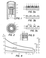
- Fig 1 is a partial perspective view with cutaway of this sheath.
- Fig 2 is a cross-sectional view of the sheath at one of the retaining members.
- Figs 3a to 3c illustrate different phases of the manufacturing process for a retaining member.
- FIG. 4 is a diagram illustrating the influence of the ratio between the spacing of the passages and their length on the porosity of the retaining member.
- Fig. 5 is an axial section view, illustrating a variant of the embodiment of FIG. 1.
- the tubular sheath illustrated in FIG 1 has a stainless steel tube 1 which can be between 1 and 3 meters in length and a diameter between 6 and 14 mm.
- This tube 1 has a portion containing nuclear fuel 2 in the form of microspheres or sintered powder or not of oxide, carbide or nitride of (U, Pu).
- This fuel 2 is retained in this portion of the tube by two retaining members 3, one of which is visible in FIG. 1, constituted by a metal strip 4 wound in a spiral around a central pin 5 provided with a flap 5a.
- One of the faces of the ribbon 4 has passages 6 extending transversely to the ribbon 4 and therefore parallel to the axis of the tube 1 when this ribbon has been driven there after having been wound in a spiral around the central peg 5 (fig 2) . It is obvious that the depth of the channels 6 in the ribbon and therefore their radial dimension once this ribbon is wound in a spiral must not exceed the size of the smallest particles of fuel 2, to avoid any loss of this fuel under any circumstances.
- the material used to make the tape must still meet several other conditions, which can be satisfied, in particular by molybdenum as well as by tungsten, as will be seen in more detail below.
- mobyldene is compatible with stainless steel, while tungsten has a very high value corresponding to that of a good protective material.
- the mobyldene retaining member For a tube with an internal diameter of 6 mm, the mobyldene retaining member will have the following expansion:
- the tube its expansion can be calculated by referring to its internal circumference given by 2 r. Using the same equation again and assuming a wall temperature of 600 ° C, the value of the radius of the tube after expansion is
- the difference in expansion between the tube 1 and the retainers 3 made of molybdenum is 0.5 hundredths of a mm and 1 hundredths of a mm for tungsten. This difference remains within a limit allowing its compensation by an elastic expansion of the turns of the retaining member 3.
- the porosity of the retaining member 3 must be of the same order of magnitude as that of the particulate fuel which is between 11 and 23%.
- the radial dimension of the porosities formed between the adjacent turns must not exceed 20 microns taking into account the size of the finest particles of the fuel. Therefore, the thinner the spiral wound tape, the greater the porosity. Theoretically this porosity can be equal to 20 microns multiplied by the length of the ribbon forming the spiral.
- maintaining a constant spacing between the turns of the ribbon cannot be achieved. This is the reason why it is proposed according to the invention to provide passages 6 transversely to the ribbon 4 by a photo-etching technique.
- the photo-etching technique used to make the transverse passages 6 on one of the faces of the ribbon 4 is well known. It consists in making a drawing on an enlarged scale of the desired image or of a portion thereof when this image is composed of a pattern repeating several times. Then we reduce this drawing to the desired dimension and we produce a photographic film 7 (fig 3) of this image reduced to its real scale.
- This film 7 constitutes a stencil or a mask which is placed on the ribbon 4, the face adjacent to the film 7 has been previously coated with a layer 8 of photosensitive resin.
- This resin can have a positive or negative action, in the first case, the exposed surface remains after development and in the second case it is the opposite.
- the sensitization of most resins is obtained using an ultraviolet light source, but resins sensitive to other lon can be chosen wavefighters. Exposing the resin to an appropriate wavelength causes the resin to polymerize. After development of this layer 8, the unprotected surface of the tape 4 can be attacked in the chemical etching solution, the concentration and the temperature of which make it possible to control the depth of the etching.
- the solution used for the chemical attack consists of one part by volume of concentrated nitric acid, one part by volume of concentrated sulfuric acid and three parts by volume of water.
- the solution is fluoridric acid used with an electrochemical process.
- Removal of the resin used as a savings during the chemical etching process can then be obtained using a solvent suitable for the type of resin used, after which the tape will be thoroughly washed to remove all traces of the chemicals used.
- the winding of the ribbon 4 on the dowel 5 can be obtained with simple means including a motor to drive the dowel 5 in rotation and a weight attached to the free end of the ribbon 4 to tension the ribbon and obtain a winding with contiguous turns .
- the speed of rotation is chosen to be relatively slow to prevent a sudden start from breaking the weld.
- the weight fixed to the ribbon is 2 kg and is fixed by means of a wire and a special clamp which keeps the plane of the ribbon horizontal. To guide the ribbon and prevent it from forming a conical winding by shifting the edges, the wire connecting the weight to the ribbon is guided by a grooved pulley, axially adjustable.
- the winding is placed in a clamping mandrel formed by two semicircular jaws corresponding to the diameter of the desired retaining member 3. These jaws are clamped around the retaining member 3 while the ribbon 4 is still under tension and a few centimeters of ribbon remain to be wound. The winding is further continued to the extent possible and the weight clamp is removed so that the rest of the tape can finish being wound up in the mandrel. To prevent a space greater than 20 microns remaining between the tube and the retaining member 3, the thickness of the outer end of the ribbon 4 is formed so as to decrease progressively.
- the retaining member is then pushed towards the end of the mandrel using a tubular pusher whose outside diameter is slightly less than that of the mandrel and whose inside diameter is slightly greater than that of the central pin 5.
- the external part of the jaws of the clamping mandrel is conical to facilitate its coaxial positioning and adjacent to one of the ends of the tube 1 for the transfer of the retaining member 3 into this tube, produced by means of a similar pusher to that used previously to bring the retaining member to the end of the mandrel.
- a retaining member 3 ' (fig. 5) consisting of a strip 4' of stainless steel wound around a central dowel 5 ', a molybdenum or tungsten disc 9 then being interposed between the fuel 2 and the retaining member 3'.
- This disc 9 has the function of forming a thermal barrier intended to reduce the temperature gradient between the nuclear fuel and the retaining member 3 ′ in order to avoid hot spots and thus allow the use of stainless steel.
- a network of channels 10 is preferably etched on the face of the disc 9 adjacent to the retaining member 3 '.
- this disc can also be obtained by sintering in order to give it an adequate porosity for the passage of gas towards the channels of the retaining member 3 '.
- a sintered disc or not will have a thickness of a few tenths of a mm and, in particular if it is not sintered and therefore porous, it will have a diameter of a few hundredths of a mm smaller than the inside diameter of the sheath 1, in order to allow the gas resulting from the fission to flow annularly towards the retaining member 3 ', the network of channels 10 of the disc 9 allowing the gas to access the channels 6 of this retaining member 3 '.
Landscapes
- Physics & Mathematics (AREA)
- Engineering & Computer Science (AREA)
- Plasma & Fusion (AREA)
- General Engineering & Computer Science (AREA)
- High Energy & Nuclear Physics (AREA)
- Monitoring And Testing Of Nuclear Reactors (AREA)
- Rigid Pipes And Flexible Pipes (AREA)
- Welding Or Cutting Using Electron Beams (AREA)
- ing And Chemical Polishing (AREA)
- Laminated Bodies (AREA)
Applications Claiming Priority (2)
| Application Number | Priority Date | Filing Date | Title |
|---|---|---|---|
| CH348/81 | 1981-01-20 | ||
| CH34881A CH640660A5 (fr) | 1981-01-20 | 1981-01-20 | Gaine tubulaire, munie de combustible nucleaire sous forme de particules frittees ou non et procede de fabrication de cette gaine. |
Publications (2)
| Publication Number | Publication Date |
|---|---|
| EP0056562A1 true EP0056562A1 (de) | 1982-07-28 |
| EP0056562B1 EP0056562B1 (de) | 1985-09-04 |
Family
ID=4184963
Family Applications (1)
| Application Number | Title | Priority Date | Filing Date |
|---|---|---|---|
| EP81810434A Expired EP0056562B1 (de) | 1981-01-20 | 1981-10-30 | Einsatz zum Festhalten des Brennstoffs in einem Brennelement |
Country Status (6)
| Country | Link |
|---|---|
| US (1) | US4627957A (de) |
| EP (1) | EP0056562B1 (de) |
| JP (1) | JPS57137895A (de) |
| CA (1) | CA1167984A (de) |
| CH (1) | CH640660A5 (de) |
| DE (1) | DE3172154D1 (de) |
Citations (5)
| Publication number | Priority date | Publication date | Assignee | Title |
|---|---|---|---|---|
| FR1289111A (fr) * | 1960-05-09 | 1962-03-30 | Gen Electric | éléments combustibles nucléaires et leur procédé de fabrication |
| US3197381A (en) * | 1959-08-17 | 1965-07-27 | Atomic Energy Authority Uk | Nuclear reactor fuel elements |
| FR1565786A (de) * | 1967-04-12 | 1969-05-02 | ||
| FR2012583A1 (de) * | 1968-07-09 | 1970-03-20 | Babcock & Wilcox Co | |
| US4036691A (en) * | 1975-12-03 | 1977-07-19 | Atomic Energy Of Canada Limited | Nuclear fuel element |
Family Cites Families (6)
| Publication number | Priority date | Publication date | Assignee | Title |
|---|---|---|---|---|
| US4163689A (en) * | 1965-12-03 | 1979-08-07 | The United States Of America As Represented By The United States Department Of Energy | Vented nuclear fuel element |
| US3573168A (en) * | 1967-05-16 | 1971-03-30 | Atomic Energy Authority Uk | Nuclear fuel venting elements for the discharge of fission gases |
| FR1537172A (fr) * | 1967-07-13 | 1968-08-23 | Commissariat Energie Atomique | Elément de combustible nucléaire à évent |
| US3953288A (en) * | 1970-03-24 | 1976-04-27 | The United States Of America As Represented By The United States Energy Research And Development Administration | Gas venting |
| US3801447A (en) * | 1971-11-16 | 1974-04-02 | W Heenan | Ventillation of nuclear reaction fuel rods |
| JPS5310237B2 (de) * | 1973-02-21 | 1978-04-12 |
-
1981
- 1981-01-20 CH CH34881A patent/CH640660A5/fr not_active IP Right Cessation
- 1981-10-30 EP EP81810434A patent/EP0056562B1/de not_active Expired
- 1981-10-30 DE DE8181810434T patent/DE3172154D1/de not_active Expired
- 1981-11-25 CA CA000390908A patent/CA1167984A/en not_active Expired
-
1982
- 1982-01-14 JP JP57003561A patent/JPS57137895A/ja active Pending
-
1984
- 1984-08-31 US US06/647,251 patent/US4627957A/en not_active Expired - Fee Related
Patent Citations (5)
| Publication number | Priority date | Publication date | Assignee | Title |
|---|---|---|---|---|
| US3197381A (en) * | 1959-08-17 | 1965-07-27 | Atomic Energy Authority Uk | Nuclear reactor fuel elements |
| FR1289111A (fr) * | 1960-05-09 | 1962-03-30 | Gen Electric | éléments combustibles nucléaires et leur procédé de fabrication |
| FR1565786A (de) * | 1967-04-12 | 1969-05-02 | ||
| FR2012583A1 (de) * | 1968-07-09 | 1970-03-20 | Babcock & Wilcox Co | |
| US4036691A (en) * | 1975-12-03 | 1977-07-19 | Atomic Energy Of Canada Limited | Nuclear fuel element |
Also Published As
| Publication number | Publication date |
|---|---|
| US4627957A (en) | 1986-12-09 |
| DE3172154D1 (en) | 1985-10-10 |
| EP0056562B1 (de) | 1985-09-04 |
| JPS57137895A (en) | 1982-08-25 |
| CH640660A5 (fr) | 1984-01-13 |
| CA1167984A (en) | 1984-05-22 |
Similar Documents
| Publication | Publication Date | Title |
|---|---|---|
| CA2665307C (fr) | Procede et installation pour l'introduction d'un fil fourre dans un bain de metal en fusion | |
| FR2479536A1 (fr) | Perfectionnements aux tubes guides des assemblages combustibles pour reacteur nucleaire et procede de demontage de ces tubes guides | |
| FR2551876A1 (fr) | Instrument de mesure d'une vitesse de rotation et son procede de fabrication | |
| FR2700058A1 (fr) | Elément constituant interne d'un réacteur de fusion. | |
| EP2136373B1 (de) | Steuerstabbündel zum Regulieren der Reaktivität des Kerns eines Atomreaktors | |
| EP0056562B1 (de) | Einsatz zum Festhalten des Brennstoffs in einem Brennelement | |
| WO1988009998A1 (fr) | Dispositif pour empecher la penetration dans le sol d'un coeur de reacteur nucleaire fondu | |
| EP0133384B1 (de) | Verfahren zur Herstellung eines Mantels, insbesondere für Behälter von Tiefsttemperaturflüssigkeit, und so erlangter Mantel | |
| FR2590714A1 (fr) | Element combustible pour reacteur surgenerateur | |
| EP0021912B1 (de) | Verfahren und Vorrichtung zur Befestigung eines im Kernbrennelementbündel anwesenden Führungsrohres mit den Endplatten dieses Bündels | |
| FR2470432A1 (fr) | Nouvelle barre de reglage pour reacteur nucleaire | |
| FR2818736A1 (fr) | Procede et dispositif de mesure de l'epaisseur d'une couche d'oxyde sur la gaine de crayons dans un assemblage de combustible | |
| EP0370884B1 (de) | Brennelementbündelstab für Druckwasserkernreaktor | |
| CH657699A5 (fr) | Dispositif de declenchement artificiel d'eclairs de foudre. | |
| EP0551783B1 (de) | Verfahren und Vorrichtung zur zerstörungsfreien Prüfung einer Wand eines mit einer radioaktiven Flüssigkeit gefüllten Behälters | |
| FR3040234B1 (fr) | Assemblage pour reacteur nucleaire de type rnr-na, a boitier muni de plaquettes d'espacement a raideur amelioree | |
| FR2668291A1 (fr) | Procede et dispositif de reglage du courant de fluide de refroidissement d'un assemblage combustible d'un reacteur a eau sous pression. | |
| FR2517866A1 (fr) | Assemblage combustible pour un reacteur nucleaire sous-modere | |
| EP0145514B1 (de) | Kernbrennstoffelement | |
| EP0122191B1 (de) | Verfahren zur Herstellung eines Brennstoffelementes und nach diesem Verfahren hergestelltes Element | |
| EP0296953A1 (de) | Brennelement in Modulform, Modulkapsel für ein solches Element und Herstellungsverfahren einer Modulkapsel | |
| EP0296954A1 (de) | Neutronenabsorberelement in Modulform und Modulkapsel für ein solches Element | |
| FR2533742A1 (fr) | Procede pour envelopper par un fil des barreaux de combustible nucleaire | |
| FR3077411A1 (fr) | Panier de rangement pour matieres radioactives, presentant un encombrement optimise ainsi que des logements de geometrie plus precise | |
| FR2667533A1 (fr) | Procede pour decouper un tube metallique par induction et application a la separation des combustibles irradies de leur gaine metallique. |
Legal Events
| Date | Code | Title | Description |
|---|---|---|---|
| PUAI | Public reference made under article 153(3) epc to a published international application that has entered the european phase |
Free format text: ORIGINAL CODE: 0009012 |
|
| AK | Designated contracting states |
Designated state(s): BE CH DE FR GB IT |
|
| 17P | Request for examination filed |
Effective date: 19821122 |
|
| ITF | It: translation for a ep patent filed | ||
| GRAA | (expected) grant |
Free format text: ORIGINAL CODE: 0009210 |
|
| RAP1 | Party data changed (applicant data changed or rights of an application transferred) |
Owner name: GESELLSCHAFT ZUR FOERDERUNG DER INDUSTRIEORIENTIER |
|
| AK | Designated contracting states |
Designated state(s): BE CH DE FR GB IT LI |
|
| REF | Corresponds to: |
Ref document number: 3172154 Country of ref document: DE Date of ref document: 19851010 |
|
| PLBE | No opposition filed within time limit |
Free format text: ORIGINAL CODE: 0009261 |
|
| STAA | Information on the status of an ep patent application or granted ep patent |
Free format text: STATUS: NO OPPOSITION FILED WITHIN TIME LIMIT |
|
| 26N | No opposition filed | ||
| PGFP | Annual fee paid to national office [announced via postgrant information from national office to epo] |
Ref country code: BE Payment date: 19890106 Year of fee payment: 8 |
|
| PG25 | Lapsed in a contracting state [announced via postgrant information from national office to epo] |
Ref country code: GB Effective date: 19891030 |
|
| PG25 | Lapsed in a contracting state [announced via postgrant information from national office to epo] |
Ref country code: LI Effective date: 19891031 Ref country code: CH Effective date: 19891031 Ref country code: BE Effective date: 19891031 |
|
| BERE | Be: lapsed |
Owner name: G-ZUR FORDERUNG DER INDUSTRIEORIENTIERTEN FORSCHU Effective date: 19891031 |
|
| GBPC | Gb: european patent ceased through non-payment of renewal fee | ||
| PG25 | Lapsed in a contracting state [announced via postgrant information from national office to epo] |
Ref country code: FR Effective date: 19900629 |
|
| REG | Reference to a national code |
Ref country code: CH Ref legal event code: PL |
|
| PG25 | Lapsed in a contracting state [announced via postgrant information from national office to epo] |
Ref country code: DE Effective date: 19900703 |
|
| REG | Reference to a national code |
Ref country code: FR Ref legal event code: ST |